SECTION 3-A 1958 BUICK ENGINE FUEL AND EXHAUST SYSTEMS SPECIFICATIONS AND GENERAL DESCRIPTION
3-1 1958 BUICK SPECIFICATIONS, FUEL AND EXHAUST SYSTEMS
General Specifications
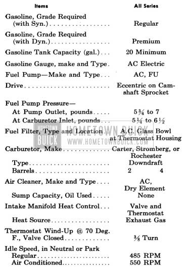
1958 Buick Fuel and Exhaust Systems Specifications
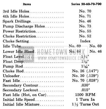
1958 Buick Stromberg Carburetor Calibrations
IMPORTANT: Calibrations are governed by the CODE number stamped on air horn directly above the fuel inlet.
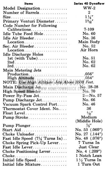
1958 Buick Stromberg Carburetor Calibrations Specifications
1958 Buick Carter Carburetor Calibrations
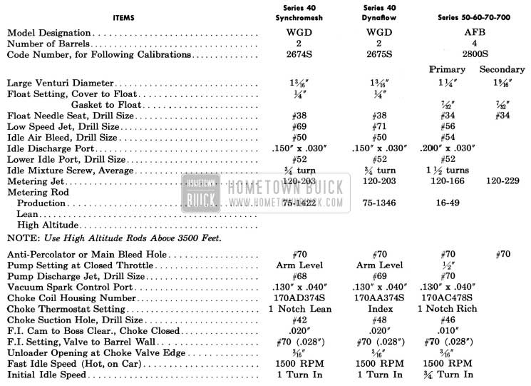
1958 Buick Carter Carburetor Calibrations Specifications
1958 Buick Rochester Carburetor Calibrations
IMPORTANT: Calibrations are governed by the CODE number stamped on air horn.
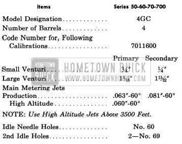
1958 Buick Rochester Carburetor Calibrations Specifications
1958 Buick Rochester Carburetor Calibrations Specification
3-2 DESCRIPTION OF 1958 BUICK FUEL SYSTEM
1958 Buick Gasoline Tank, Feed Pipe, and Filter
The 1958 Buick gasoline tank is attached by two strap type supports to the body under the trunk compartment, where it is seated against strips of anti-squeak material. Two internal baffles spot-welded to the upper half at centerline of tank support seats act as struts to maintain the shape of tank and prevent flexing due to weight of gasoline and pull of the supporting straps.
The 1958 Buick gas tank filler is soldered into an opening at the rear upper center of the tank, and is accessible by lifting a door in the center of the rear bumper. The tank is vented at a special pipe rather than at the filler cap. This breather pipe is located at the forward top center of the tank and has a rubber hose extending from it up into the area just under the rear spring cross member. See figure 3-1.
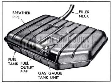
1958 Buick Fuel Tank
The 1958 Buick tank outlet is located at the top forward left center of the tank. It consists of a combination feed pipe and gas gauge tank unit. See figure 3-2.
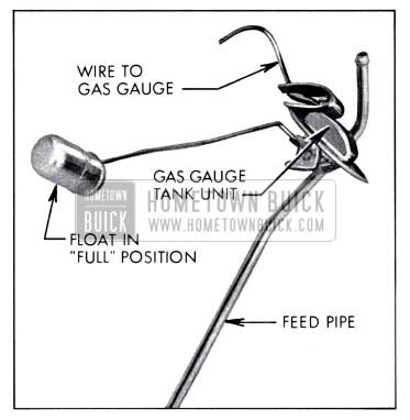
1958 Buick Gas Gauge Tank Unit
All 1958 Buick fuel lines are made of synthetic rubber hose. This hose is supported along the outside of the right frame rail by clips. All connections are made to non-corrosive fittings using wire hose clamps. See figure 3-3.
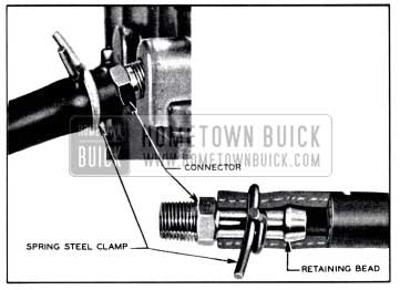
1958 Buick Fuel Lines and Clamps
A glass bowl fuel filter is located in the line between the fuel pump and the carburetor. In this location, the filter can be visually inspected or cleaned without removing the air cleaner.
1958 Buick Fuel Pump, Carburetor, and Automatic Choke
The 1958 Buick fuel pump is mounted on the lower right side of the timing chain cover. It is actuated by a hardened, chrome-plated, stamped steel eccentric mounted on the front side of the camshaft sprocket. The pump is inverted, thereby placing it in a lower, cooler location. It has a built in air dome with a diaphragm to damper out pulsations in the fuel stream. The construction and operation of the pump are described in Section 3-D.
Engines of all series are equipped in production with either a Carter, Stromberg, or Rochester downdraft type carburetor. Each make is considered standard and it is not intended that these units be interchanged to provide “optional” equipment.
Series 40 engines use a 2-barrel carburetor and Series 50-60-70-700 engines use a 4-barrel carburetor. All 1958 Buick carburetor assemblies include automatic choke mechanism and a carburetor starter switch.
The Carter carburetors are described in Section 3-E (2-barrel) and Section 3-F (4-barrel). The Stromberg carburetor is described in Section 3-G. The Rochester carburetor is described in Section 3-H. The carburetor starter switches are described in Section 10-E.
1958 Buick Air Cleaner and Intake Silencer
All series engines are equipped with heavy duty dry element air cleaners combined with 1958 Buick intake silencers. The 1958 Buick air cleaner removes abrasive dust and dirt from the air before it enters the engine through the carburetor. The intake silencer reduces to a very low level the roaring noise made by the air as it is drawn through the intake system. The cleaner and silencer also functions as a flame arrester in event of “backfire” through the intake system.
There are four air cleaner and silencer assemblies, one for each of the following: two barrel carburetor coil spring cars, two barrel carburetor Air Poise cars, four barrel carburetor coil spring cars, and four barrel carburetor Air Poise cars.
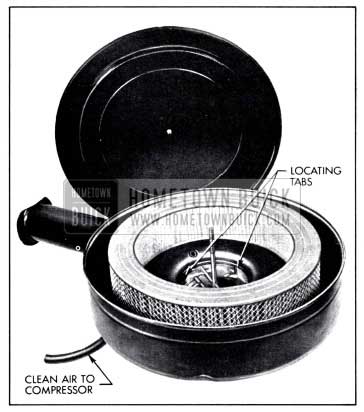
1958 Buick Air Cleaner and Silencer Assembly
The two barrel carburetor air cleaner uses a support bracket under the air inlet tube; the four barrel air cleaner has no support bracket. The Air Poise air cleaner has a small pipe projecting forward for the purpose of supplying clean air to the compressor; the coil spring air cleaner has no pipe. Care must be used to be sure that Air Poise cleaners are not used on coil spring cars. On Air Poise cars the air compressor inlet hose must be properly assembled over the cleaner outlet pipe or dirt will get into both the engine and the compressor.
All four barrel carburetor air cleaners have two locating tabs which engage two projections on the carburetor air horn to locate the large air inlet tube firmly in position about 15° to the right of the center line of the engine. The small pipe on air ride air cleaners conducts air from just above the carburetor through a hose to the inlet of the air compressor. This not only insures a clean air supply, but also eliminates compressor inlet noise.
The 1958 Buick air cleaner element is of the disposable dry type. It consists of a cylindrical cellulose fiber material, pleated to permit maximum filter area. On each end of this cylinder, the fiber is embedded in plastic end plates to provide an efficient dust seal. On both sides of the fiber, rust resistant wire screen furnishes compressive strength; the fine mesh of the inner screen also acts as a flame arrester in case of backfire.
The fiber of the element passes air through with low restriction, but any dust or dirt in the air deposits on the pleated outer surface. This fiber is flame proofed and will retain its shape and filtering efficiency under normal concentrations of gasoline vapor, engine oil and water vapor. For normal operating conditions, the element should be cleaned and inspected every 5000 miles (every 1000 miles under dusty operating conditions). See paragraph 1-2 step 2 for the cleaning procedure. Every 15,000 miles the element should be replaced with a new one.
1958 Buick Carburetor Throttle Control Linkage
The 1958 Buick carburetor throttle control linkage is designed to provide positive control of the throttle valves through their entire range without being affected by movement of the engine on its rubber mountings. The linkage also serves to operate the carburetor starter switch when cranking the engine.
The 1958 Buick accelerator pedal rod is connected to a lever on the lower end of an equalizer shaft which is mounted between the body cowl and the rear end of engine. Movement of the pedal rotates the equalizer shaft, which actuates the carburetor throttle shaft through an upper lever and connecting rod. The throttle return spring is connected to the equalizer shaft upper lever and to an anchor bracket on engine. See figure 3-11.
On cars equipped with Dynaflow Drive, a dash pot is mounted in position to be contacted by an arm of the carburetor throttle lever as the throttle is closed. The dash pot cushions the closing of throttle valves to prevent sudden shut off which might cause the engine to stall when the accelerator pedal is suddenly released. The 1958 Buick throttle linkage also actuates a separate lever •and rod connected to the stator control valve in the Dynaflow.
3-3 DESCRIPTION OF 1958 BUICK INTAKE AND EXHAUST SYSTEMS
1958 Buick Intake Manifold and Heat Control
A low-restriction, dual (2 section) intake manifold is bolted to the inner edges of both cylinder heads, where it connects with all inlet ports. The end branches of each section run at 90 degrees to the connecting middle branch, thereby forming a T-junction at the dividing point which assures a uniform division and distribution of fuel to all cylinder inlets. Each manifold section feeds four cylinders-two in each bank. See figure 3-5.
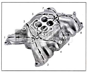
1958 Buick Intake Manifold Distribution
The Series 40 2-barrel carburetor feeds one barrel into each section of its 2-port manifold. The Series 50-60-70-700 4-barrel carburetor feeds one primary and one secondary barrel into each section of its 4-port manifold.
The 1958 Buick intake manifold is heated and hot spots are provided at the T-junction dividing points by crossover chambers cast along the outer walls of each end branch. These chambers connect to the two middle exhaust passages in each cylinder head. See figure 3-6.
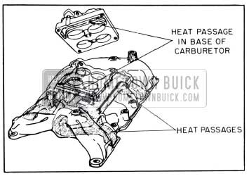
1958 Buick Intake Manifold Heat Chambers
Hot spots located at the dividing junctions aid in vaporizing the heavier particles of fuel which are swept against the outer walls due to their greater momentum. The heated intake manifold also aids in obtaining a uniform fuel distribution.
The 1958 Buick intake manifold is heated by exhaust gas cross-over passages cast under the center section of the manifold. These passages connect to the two middle exhaust passages in each cylinder head. See figure 3-6. Exhaust heat is supplied directly to the carburetor mounting surface by two holes drilled from the mounting surface into the cross-over passages. The carburetors are designed to conduct this heat around the throttle valve area to reduce engine stalling due to carburetor icing.
A heat control valve with a bi-metal thermostat is located in the right exhaust manifold. See figure 3-7.
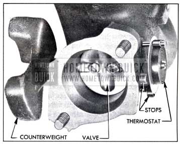
1958 Buick Exhaust Manifold Valve
When the engine is cold and the thermostat closes the valve, the resulting back pressure in the manifold forces exhaust gas through the crossover passages in the intake manifold to the left exhaust manifold. As the engine warms up and the thermostat releases the valve, the flow of hot gas through the crossover chamber is reduced. Restricted openings in the metal intake manifold gaskets further reduce the flow of gases through the manifold when the engine is warm and the heat valve is open.
1958 Buick Exhaust Manifolds, Pipes, and Mufflers
Each cylinder exhausts through an individual port into a separate branch of the 1958 Buick exhaust manifold. This manifold, referred to as the double “Y” type, is designed to provide a separation of 270 degrees crankshaft rotation between any two exhaust impulses in one branch of the manifold. This elimination of overlap within any given branch of the manifold permits valve timing that improves engine efficiency, minimizes exhaust valve burning, and effects more complete scavanging of exhaust gas from the cylinder.
A dual exhaust system is standard equipment on 1958 Buick Series 70-700 cars and is optional on all Series 40-50-60 cars. See figure 3-8. The right exhaust manifold is the same on either single or dual exhaust cars. The left exhaust manifold, the exhaust pipes, the mufflers, and the tail pipes are not interchangeable between single and dual exhaust cars.
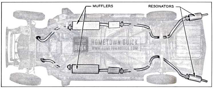
1958 Buick Dual Exhaust System
The right manifold contains the valve which controls the supply of exhaust heat to the intake manifold, as described above (subpar. a). It also contains the carburetor choke heat stove which consists of an alloy steel heating tube mounted in a drilled hole in the manifold and a heating chamber located on the outside of the manifold. Heated air is drawn from the heat stove through an insulated pipe into the automatic choke housing.
All joints between exhaust manifolds, exhaust pipes, two-section mufflers, and tail pipes are of the ball joint connector type. These joints make for easy connection, disconnection, and alignment of exhaust system parts. No gaskets are used in the entire exhaust system.
The 1958 Buick muffler is an oval-shaped, dynamic flow type having very low back pressure. It is double wrapped of heavy gauge sheet steel with a layer of asbestos placed between wrappings to aid in reduction of noise transfer and prevents any “oil-canning” effect. The muffler and exhaust pipes are supported by free hanging, rubber-fabric mountings which permit free movement but eliminate transfer of noise and vibration into the passenger compartment.
1958 Buick dual exhaust systems have a resonator located under each rear fender. Resonator drain holes must always be down, or they will fill with water.
On 1958 Buick dual exhaust jobs only, the pitman arm will strike the left exhaust pipe if it is not properly positioned. Position exhaust pipe so that it cleats the pitman arm approximately 1 inch when front wheels are turned full left.
Leave A Comment
You must be logged in to post a comment.