SECTION 9-A 1958 BUICK BRAKE SPECIFICATIONS, DESCRIPTION, OPERATION
9-1 1958 BUICK BRAKE SPECIFICATIONS
Tightening Specifications
Use a reliable torque wrench to tighten the parts listed, to insure proper tightness without straining or distorting parts. These 1958 Buick brake specifications are for clean and lightly lubricate threads only; dry or dirty threads produce increased friction which prevents accurate measurement of tightness.
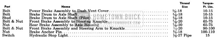
1958 Buick Brake Tightening Specifications
General Specifications
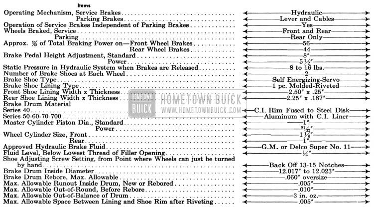
1958 Buick Brake Specifications
9-2 DESCRIPTION OF 1958 BUICK BRAKE MECHANISM
The 1958 Buick brake mechanism includes a 1958 Buick brake drum and a 1958 Buick brake assembly at each wheel, and two separate and independent control systems for applying the brakes (1) Parking brake control system (2) Service brake control system.
1958 Buick Wheel Brake Assemblies
All rear brake drums and Series 40 front brake drums consist of a cast iron rim fused to a pressed steel disk. The cast iron rim provides an ideal braking surface and increased brake lining life. An external web around the circumference prevents distortion and aids in dissipation of heat.
All 1958 Buick Series 50-60-70-700 front brake drums are cast aluminum alloy with a cast iron liner. The aluminum section has cast ribs and fins to help dissipate heat to the air.
The 1958 Buick brake assembly at each wheel uses a primary (front) and a secondary (rear) brake shoe of welded steel construction, with one-piece molded lining attached by tubular rivets. The primary shoe lining is shorter than the secondary shoe lining and is of different composition; therefore the two shoes are not interchangeable. See figure 9-1.
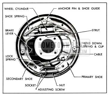
1958 Buick Rear Wheel Brake Assembly-Right
Each 1958 Buick brake shoe is held against the backing plate by a hold-down spring, pin, and cup which allow free movement of the shoe. The notched upper end of each shoe is held against the single anchor pin by a heavy coil spring. An adjusting screw and lock spring connects the lower ends of both shoes together and provides adjustment for clearance with the 1958 Buick brake drum.
A hydraulic wheel cylinder mounted on the backing plate between the upper ends of the 1958 Buick brake shoes forces the shoes against the 1958 Buick brake drum when the service brakes are applied. On rear wheels only, a lever mounted on each secondary shoe and connected to the primary shoe by a strut is used for applying the shoes when used as parking brakes. See figure 9-1.
When the 1958 Buick brake shoes contact the rotating drum, in either direction of car travel, they move with the drum until the rearward shoe is stopped by the anchor pin and the forward shoe is stopped by the rearward shoe through the connecting adjusting screw. Frictional force between drum and shoe lining tries to rotate each shoe outward around its anchor point but the drum itself prevents this rotation; consequently the shoes are forced more strongly against the drum than the applying force is pushing them. See figure 9-2. It is also evident that the force applied by the drum to the forward shoe is imparted to the rearward shoe through the connecting adjusting screw.
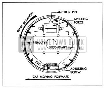
1958 Buick Brake Shoe Action
Utilization of the frictional force to increase the pressure of shoes against the drum is called self-energizing action. Utilization of force in one shoe to apply the opposite shoe is called servo action. The self-energizing servo action of 1958 Buick brakes provides powerful braking action with relatively light pedal pressure.
1958 Buick Parking Brake Control System
The 1958 Buick parking brake control system uses a foot operated brake lever, conduit enclosed cables, brake shoe levers and struts to apply the rear wheel brakes only. The brake lever cable connects to a sheave (equalizer) located at center of the rear brake cable, with an adjusting nut to take up cable slack. Each end of the rear brake cable is attached to the free lower end of a brake shoe lever pivoted on each secondary (rear) brake shoe. A strut is mounted between each 1958 Buick brake shoe lever and the primary (front) brake shoe. See figure 9-3.
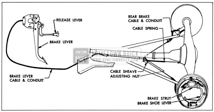
1958 Buick Parking Brake Control System
When the 1958 Buick brake lever is pushed forward the cables apply an equal pull to each brake shoe lever, and the levers and struts force all rear brake shoes into firm contact with the brake drums. A spring loaded latch automatically locks the brake lever to keep the parking brakes applied. The brake lever is released by pulling the lever release knob. A warning signal, which is standard on Series 70 and optional on Series 40-50-60, will show a red light on instrument panel if the car is operated with the parking brakes applied.
Service 1958 Buick Brake Control System – Standard Brakes
NOTE: See paragraph 9-15 for 1958 Buick power brakes.
The regular foot powered service brake control system is a pedal operated hydraulic system which applies the 1958 Buick brakes at all four wheels with equalized pressure.
The hydraulic system consists of one master cylinder connected by pipes and flexible hoses to a wheel cylinder mounted between the 1958 Buick brake shoes at each wheel. The master cylinder, pipes, hoses, and four wheel cylinders are filled with a special fluid. See figure 9-4.
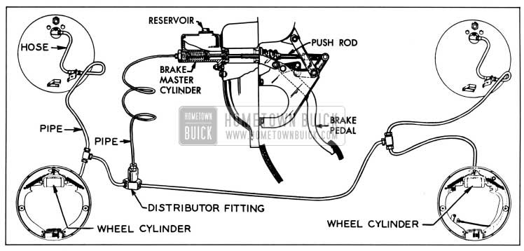
1958 Buick Service Brake Control System
The 1958 Buick brake pedal is suspended from a pivot bolt between two mounting brackets. As the 1958 Buick brake is applied, a lever on the pedal which extends above the pivot point operates a link rearward. This link in turn transmits motion to a lever on an idler, causing the idler to rotate. This rotation causes a second idler lever to push forward on the brake master cylinder push rod and clevis. The overall mechanical advantage in the standard brake linkage is approximately 6 to 1. See figure 9-4.
All pivot points in the 1958 Buick brake linkage have nylon bearings which are lubricated during installation but do not require periodic lubrication. Whenever the linkage is disassembled, however, all friction surfaces should be lightly coated with Lubriplate. Because there is no pedal stop, the pedal is stopped in the “off” position by contact of the push rod with the stop plate in the master cylinder. The only linkage adjustment possible is the pedal height adjustment (par. 9-8).
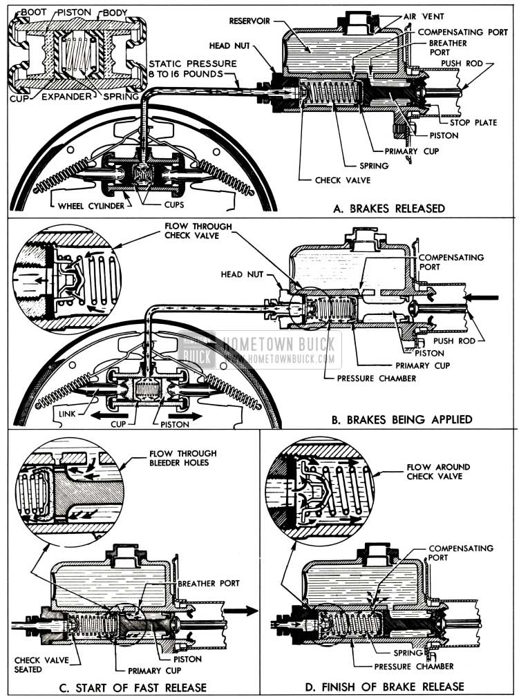
The master cylinder contains a vented reservoir for reserve fluid and a cylinder pressure chamber in which force applied to the 1958 Buick brake pedal is transmitted to the fluid which actuates the 1958 Buick brake shoes. A breather port and a compensating port permits passage of fluid between the reservoir and pressure chamber under certain operating conditions. The outlet end of the pressure chamber is closed by a head nut and gasket. A coil spring holds a check valve against the head nut and also holds a rubber primary cup against the inner end of the piston. This cup and a rubber secondary cup on the outer end of the piston prevent escape of fluid past the piston. The piston is retained in the cylinder by a stop plate and lock ring. The push rod which actuates the piston extends through the stop plate, and a rubber boot is installed over this end of the cylinder to exclude foreign matter. See figure 9-5, view A.
1958 Buick Hydraulic Brake Components
Each wheel cylinder contains two pistons and two rubber cups which are held in contact with the pistons by a central coil spring with cup expanders to provide a fluid -tight seal. The wheel cylinders cups are of a special heat resisting rubber. Cups of this material must have an expander to hold the lips of the cup out against the wheel cylinder bore. These cup expanders are crimped on each end of the wheel cylinder spring. The inlet port for brake fluid is located between the pistons so that when fluid pressure is applied both pistons move outward towards the ends of wheel cylinders. The pistons impart movement to the 1958 Buick brake shoes by means of connecting links which seat in pistons and bear against webs of shoes. Rubber boots enclose both ends of cylinder to exclude foreign matter. See figure 9-5A. A valve for bleeding the 1958 Buick brake pipes and wheel cylinder is located above the inlet port.
9-3 OPERATION OF 1958 BUICK HYDRAULIC SERVICE BRAKES
NOTE: See paragraph 9-15 for power brakes.
When the 1958 Buick brakes are fully released, the master cylinder piston is held against the stop plate and the primary cup is held just clear of the compensating port by the master cylinder spring, which also holds the check valve against its seat on the head nut. The pressure chamber is filled with fluid at atmospheric pressure due to the open compensating port and reservoir vent. All pipes and wheel cylinders are filled with fluid under a “static” pressure of 8-16 pounds, which helps to hold the lips of the wheel cylinder cups in firm contact with cylinder walls to prevent loss of fluid or entrance of air. See figure 9-5, view A.
When the 1958 Buick brake pedal is depressed to apply the brakes, the push rod forces the master cylinder piston and primary cup toward the head nut. As this movement starts, the lip of the primary cup covers the compensating port to prevent escape of fluid into the reservoir. Continued movement of the piston builds pressure in the pressure chamber and fluid is then forced through holes in the check valve and out into the pipes leading to all wheel cylinders. Fluid forced into the wheel cylinders between the pistops and cups causes the pistons and connecting links to move outward and force the brake shoes into contact with the drums. See figure 9-5, view B.
Movement of all 1958 Buick brake shoes into contact with drums is accomplished with very light pedal pressure. Since pressure is equal in all parts of the hydraulic system, effective braking pressure cannot be applied to any one drum until all of the shoes are in contact with their respective drums; therefore the system is self-equalizing. After all shoes are contacting the drums, further force on brake pedal builds up additional pressure in the hydraulic system, thereby increasing the pressure of shoes against drums.
On rapid stops some car weight is transferred from the rear to the front wheels, consequently greater braking power is required at front wheels in order to equalize the braking effect at front and rear wheels. Greater pressure is applied to front 1958 Buick brake shoes by using larger wheel cylinders, so that distribution of braking power is approximately 56% at front wheels and 47% at rear wheels.
When the 1958 Buick brake pedal is released, the pedal return spring pulls the pedal back until the push rod contacts the stop plate in master cylinder. The master cylinder spring forces the piston and primary cup to follow the push rod and also presses the check valve firmly against its seat.
At start of a fast release the piston moves faster than fluid can follow it in returning from the pipes and wheel cylinders, therefore, a partial vacuum is momentarily created in the pressure chamber. Fluid supplied through the breather port is then drawn through the bleeder holes in piston head and past the primary cup to keep the pressure chamber filled. See figure 9-5, view C.
As pressure drops in master cylinder the shoe springs retract all 1958 Buick brake shoes and the connecting links push the wheel cylinder pistons inward, forcing fluid back to master cylinder. Pressure of returning fluid causes a rubber disc to close all holes in the check valve and forces the check valve off its seat against the tension of master cylinder spring; fluid then flows around the check valve into the pressure chamber. With the piston bearing against the stop plate and the lip of the primary cup just clear of the compensating port, excess fluid which entered through the bleeder holes, or was created by expansion due to increased temperature, now returns to reservoir through the uncovered compensating port. See figure 9-5, view D.
When pressure in wheel cylinders and pipes becomes slightly less than the tension of master cylinder spring, the check valve returns to its seat on head nut to hold 8 to 16 pounds of “static” pressure in the pipes and cylinders.
Leave A Comment
You must be logged in to post a comment.