SECTION 8-B 1958 BUICK POWER STEERING GEAR AND PUMP
8-8 1958 BUICK POWER STEERING GEAR AND PUMP SPECIFICATIONS
Tightening Specifications
Use a reliable torque wrench to tighten the parts listed to insure proper tightness without straining or distorting parts. These 1958 Buick power steering gear specifications are for clean and lightly lubricated threads only: dry or dirty threads produce increased friction which prevents accurate measurement of tightness.
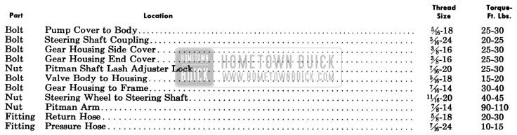
1958 Buick Power Steering Gear Tightening Specifications
1958 Buick Power Steering Gear Specifications
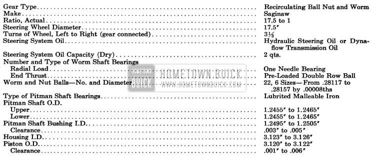
1958 Buick Power Steering Gear Specifications
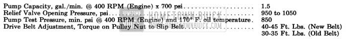
1958 Buick Power Steering Pump Specifications
1958 Buick Power Steering Gear Pump Specifications
8-9 DESCRIPTION OF 1958 BUICK POWER STEERING GEAR AND PUMP
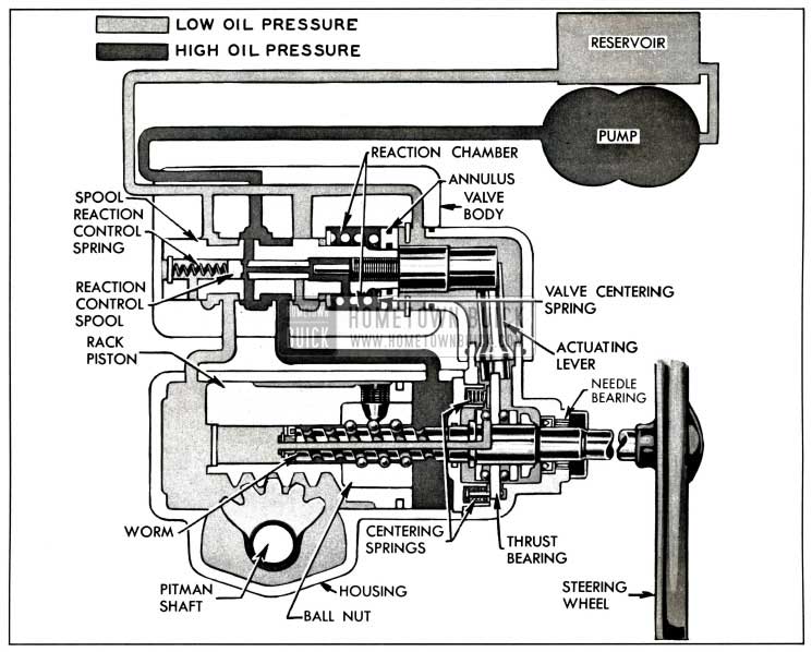
1958 Buick Power Steering is standard equipment on Series 50-70-700 and is available as optional equipment on Series 40 and 60. All cars equipped with Air-Poise suspension are equipped with power steering. This steering system consists of an in-line 1958 Buick power steering gear with the worm and ball nut, power piston and rack, and the power cylinder all on a single center line. The valve is mounted directly on the gear housing, thereby eliminating all external lines and hoses except the pressure and return lines between the valve and a high pressure pump.
The 1958 Buick engine drives the oil pump which furnishes hydraulic pressure. When the engine is not running, or when any part of the power mechanism is inoperative, steering is entirely manual and requires only slightly more effort at the steering wheel than the manual gear used as standard equipment.
With the engine running, steering is entirely manual under conditions which require an effort of less than two and three-quarters (2 3/4) pounds at the steering wheel rim. When a greater effort is required, the power mechanism operates to ASSIST in turning the front wheels. The effort then required at steering wheel rim is limited to a maximum of approximately six pounds for normal steering and parking conditions, compared to possibly fifty pounds with the standard manual gear. If some abnormal condition requires more work than the power mechanism can do, the driver must assist with increased effort at the steering wheel.
The driver’s effort on the steering wheel is always proportional to the force necessary to turn the front wheels. When the effort on the wheel drops to less than two and three-quarters (2 3/4) pounds as the turn is completed, power assistance ceases. When the wheel is released to recover from a turn, the front wheels may return to the straight-ahead position in the usual manner without assistance or interference from the power mechanism. Through this conventional steering action the driver always has the “feel” of steering.
It should be noted that power steering always follows the manual steering action. No steering action is obtained except through the manual guidance of the driver.
The hydraulic units and steering gear housing are filled with the same oil as specified for Dynaflow transmissions.
1958 Buick Power Steering Gear Assembly
The 1958 Buick power steering gear assembly is the recirculating ball nut and worm type, having a ratio of 17.5 to 1.
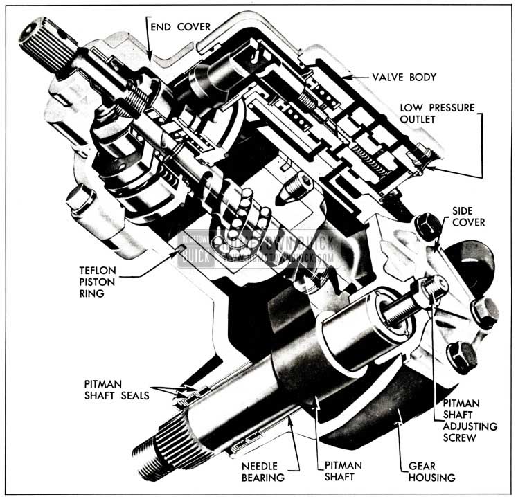
The upper end of the pitman shaft has a gear section meshing with a rack which is a part of the power piston. This rack-piston slides in the gear housing which is cylindrical. The rack-piston assembly consists of power piston and rack with a Teflon piston ring and also a ball nut locked rigidly in place with a retaining screw. See figure 8-11.
1958 Buick Power Steering Gear Assembly
A worm shaft turns in the ball nut using selectively fitted steel balls as a rolling thread. The ball groove is shallower in the center of the worm so that when the proper size balls are used, there is a slight worm to ball nut pre-load in the straight ahead position.
Worm shaft radial loads are transmitted to the gear housing through a needle bearing at the upper end and through the rack-piston at the lower end. Worm shaft end thrust is caused by the tendency of the worm to thread itself into or out of the ball nut as the wheel is turned right or left. This end thrust is absorbed entirely by a pre-load thrust bearing. Any end thrust causes a movement of the thrust bearing center race which is held in position by centering springs; the more the end thrust, the more the movement of the center race up to a point where it bottoms in its housing. This movement of the center race is transmitted to the control valve through the valve actuating lever.
The upper steering shaft is a separate shaft supported in the steering column jacket. Its upper end is supported by a ball bearing; its lower end by an adapter and ball bearing assembly.
The upper steering shaft is connected to the 1958 Buick power steering gear worm shaft through a flexible coupling. This flexible coupling helps absorb minor shocks and vibrations, dampens out hydraulic noises and gear rattle, and also allows slight variations in alignment between the power gear assembly and the steering column jacket assembly.
1958 Buick Hydraulic Valve
The 1958 Buick hydraulic valve controls the flow of oil from the pump to the proper side of the power rack-piston when power assistance is required and cuts off this flow when power assistance is not required. It also regulates the effort at steering wheel within the normal range of two and three-quarters (2 3/4) to six (6) pounds so that this effort is proportional to the force necessary to turn the front wheels, thereby providing the “feel” of steering previously mentioned. See Figure 8-11.
The valve spool is held in a neutral position by means of a valve centering spring located in the valve reaction chamber plus the thrust bearing centering springs. The hydraulic valve contains a second spool, located in the center of the valve spool. This second spool establishes the maximum pressure that may be produced in the reaction chamber and thereby decreases the hand wheel effort when parking.
During a left turn, the thrust bearing is moved up and in a right turn the thrust bearing is moved down. This in turn moves the actuating lever up or down which is connected to the link on the valve spool. The movement of the actuating lever moves the control valve spool which directs the oil flow through the control valve to the cylinder.
Oil Pump
The oil pump, which is mounted on the engine in position to be driven by a belt from the crankshaft balancer, converts some engine power into oil pressure which is used by the power cylinder and rack-piston to rotate the pitman shaft. The oil pump used on Air-Poise suspension jobs is bolted to the rear of the Air Poise compressor. This oil pump rotor is turned by an extension of the compressor shaft.
The pump houses a slotted driving hub or rotor in which ten vanes slide radially outward to contact the hardened and ground inside surface of a ring. As the shaft and rotor rotates, centrifugal force and fluid pressure against the inner ends cause the vanes to follow the cam contour of the ring, which is so shaped that two opposing pumping chambers are formed. In each pumping chamber, the increasing and decreasing pockets formed between the rotor, vanes, and ring propel the oil from the reservoir into a discharge cavity in the pump cover.
Oil flows from the discharge cavity into the exit port in pump cover through a restricted passage (.1285″ dia.); therefore, pressure in the discharge cavity is always greater than that in the exit port. A control valve assembly regulates the opening of another passage through which oil may be by-passed back to the reservoir. See Figure 8-12 and 13. The valve assembly includes a flow valve and a pressure relief valve.
When the pump is running without demand for steering pressure, pressure in the discharge cavity is high enough to push the flow control valve open against a spring load of approximately ten pounds. A small orifice leads oil from the exit port into the spring chamber and this pressure tends to close the valve. Since pressure in the discharge cavity is always greater than in the exit port the valve is not closed, and the flow valve action depends on the spring load and the difference in pressure on the inner and outer ends of the valve.
When power steering is demanded and the 1958 Buick power steering gear control valve restricts free circulation of oil as described later (par. 8-10), the pump pressure builds up rapidly. When pump output pressure reaches a predetermined maximum the increased pressure in the flow valve spring chamber forces the pressure relief valve open, and oil escapes from the spring chamber into the by-pass passage. As oil pressure is relieved in the spring chamber, the high pressure in the pump discharge cavity overcomes the spring load to completely open the flow valve. See Figure 8-12.
1958 Buick Power Steering Pump Cross-Section – Standard Pump
Oil is pumped into the by-pass passage until the line pressure opposing the pump drops below the relief valve setting, permitting this valve to close. The flow valve then resumes normal operation.
The flow valve starts to open at 300-400 RPM of pump and is functioning when pump idles at 465 RPM (400 RPM of engine). The minimum flow the pump must produce is 1.5 gal. per minute at 465 RPM against a pressure of 700 psi. The flow valve permits a maximum flow of 2.1 gal. per minute at 1500 RPM against a pressure of 50 psi. The pressure relief valve is set for 950 to 1050 psi.
The power steering pump identification number is stamped in the rear vertical surface of the pump. The first 3 digits show the day of the year (1 through 365) the pump was tested. Next is a letter for manufacturer identification (S for Saginaw). The last digit shows the year (7 for 1957, etc.)
Reservoir and Hoses
The reservoir is mounted on top of the oil pump and provides a reserve supply of oil to assure complete filling of the hydraulic system. The standard reservoir is vented at the cover bolt by bleed grooves in the washer which permit escape of any air that may be introduced into the system during assembly of the various units and maintains atmospheric pressure in the reservoir.
On jobs equipped with 1958 Buick Air-Poise suspension the pump is vented thru the crankcase, not thru the reservoir cover. A flat washer is used on the compressor pump reservoir bolt.
On cars equipped with 1958 Buick Air Poise suspension the reservoir differs from the one used on standard suspension jobs. This reservoir, which is designed to supply oil to the Air Poise compressor, is not interchangeable with the reservoir on pumps used on cars not equipped with Air Poise. See Figure 8-13.
1958 Buick Power Steering Pump Cross-Section – Air-Poise Pump
The compressor reservoir has an inlet and an outlet connected to the compressor by drilled passages in the pump body. Oil returning from the gear enters the return hose inlet. Some passes through the filter in the pump reservoir while the remainder flows through a screen and over into a cavity which is connected to the compressor reservoir. Thus, the same oil level is maintained in the cavity and in the compressor reservoir. If the screen and filter should become plugged, the pressure of the oil overcomes the spring tension and forces the retainer and spring away from the filter, allowing oil to escape between the filter and retainer.
In order to remove any foreign matter which may have entered the oil while it passed through the system, a wire mesh filter has been installed in the reservoir through which all the return oil passes prior to its mixing with the oil contained in the reservoir.
A pressure line hose and a return line hose connect the oil pump to the hydraulic valve in the 1958 Buick power steering gear.
8-10 OPERATION OF 1958 BUICK HYDRAULIC POWER MECHANISM
When the 1958 Buick steering wheel is turned, the ball nut must move axially along the worm shaft in order to rotate the pitman shaft and thereby turn the front wheels through the connecting linkage. Movement of the ball nut is opposed by the force necessary to turn the front wheels, consequently, the worm shaft tends to move endwise through the ball nut. The ball nut and worm shaft act like a screw jack to thrust a load against the worm thrust bearing, tending to move the bearing.
Movement of the thrust bearing (and worm shaft) is opposed by thrust bearing springs and valve centering springs in the hydraulic valve, therefore, the thrust load must exceed the total preload of the springs before the worm shaft can actually move endwise. Consequently, the worm shaft will move endwise only when the force necessary to turn the front wheels requires an effort of more than two and three-quarters (2 3/4) pounds at the steering wheel.
Neutral or Straight-Ahead
1958 Buick Oil Circulation in Neutral or Straight Ahead Position
Figure 8-14 shows the valve in the neutral or straight-ahead position and by following the arrows, which indicate oil flow, it is noted that the oil flows from the pump, through the opencenter valve and back to the pump reservoir without ever approaching the power cylinder. All passages are open in the neutral position and the valve remains in this position at all times except when effort applied to steering wheel is more than two and three quarters (2 3/4) pounds. The valve’s “opencenter” feature reduces losses to a minimum. It should be understood that the power cylinder is full of oil at all times, although in the straight-ahead position the pressure on both sides of the piston is equal and very low (approximately 15 to 20 psi). This oil acts as a cushion that absorbs road shocks so they are not transferred to the steering wheel, thus giving safer and more effortless driving. In addition, this oil lubricates all internal components of the gear making it unnecessary to grease the gear at any time.
Right Turn
1958 Buick Oil Circulation in Right Turn
Figure 8-15 illustrates the function of the gear when the steering wheel is turned to the right. Due to the turning resistance, the steering worm tends to screw down into the ball nut; therefore, as the driver applies right turn effort to the steering wheel, the worm is allowed to move downward a slight amount. As the worm moves downward it also moves the thrust bearing downward, which, in turn, causes the valve actuating lever to move the valve spool upward. As this spool moves, the relationship between the grooves in the spool and the grooves in the valve housing is changed so that the lower spool groove is no longer as fully open to return but is opened wider to the pressure side of the pump, and the upper spool groove is opened, more fully to return but less fully to the pressure side of the pump. This causes the oil to flow into the lower half of the pressure cylinder and force the piston upward toward the driver. As the piston moves upward, it moves the power rack with it, which in turn, applies turning effort to the pitman shaft.
The oil in the upper end of the cylinder is simultaneously forced out through the valve and back to the pump reservoir. The higher the turning resistance, the more the valve spool is displaced, and the higher the oil pressure on the lower end of the piston.
Left Turn
1958 Buick Oil Circulation in Left Turn
Figure 8-16 illustrates the function of the gear when the steering wheel is turned to the left. Due to turning resistance the steering worm tends to screw up and out of the ball nut; therefore, as the driver applies left turn effort to the steering wheel, the worm is allowed to move upward a slight amount.
As the worm moves upward it also moves the thrust bearing upward, which in turn causes the valve actuating lever to move the valve spool downward.
As the spool moves, the relationship between the grooves in the spool and the grooves in the valve housing is changed. The upper spool groove is no longer as fully open to return but is opened wider to the pressure side of the pump. The lower spool groove is opened more fully to return but less fully to the pressure side of the pump. This causes the oil to flow into the upper half of the pressure cylinder and force the piston downward away from the driver.
As the piston moves downward, it moves the power rack with it which in turn applies turning effort to the pitman shaft.
The oil in the lower end of the cylinder is simultaneously forced out through the valve and back to the reservoir.
The higher the turning resistance, the more the valve spool is moved, and the higher the oil pressure on the upper end of the piston.
When oil pressure is directed to the upper end of the rack-piston for a left turn, the oil pressure in this chamber is confined by the oil seal in the adapter, the rack-piston oil rings, and the oil seal on the end of the worm.
To prevent pressure or vacuum at the end of the worm in the rack-piston, this chamber is vented by a passage inside the worm which extends into the end cover chamber.
Steering Effort Reaction
The instant the driver stops applying steering effort to the wheel, the valve spool is forced back into its neutral position by three forces; the centering spring in the valve reaction chamber, the centering springs on the thrust bearing, and the hydraulic reaction in the valve reaction chamber. When this happens, the oil pressure is again equal on both sides of the piston and the steering geometry of the car causes the wheels to return to the straight-ahead position.
Simultaneously with the turn explained above, oil pressure increases in the valve reaction chamber. This is the feature in the valve that gives the driver the “feel of the road” at all times. As the driver turns to the right and oil pressure builds up in the cylinder, equal oil pressure builds up in this reaction chamber. The more effort required to turn the front wheels, the higher the pressure builds in the reaction chamber. Since it is this pressure that tends to recenter the valve, the driver has to apply more effort to the steering wheel as the pressure in this chamber increases. To summarize, the more the turning resistance, the greater the pressure in this chamber, and therefore, the more effort the driver must apply to the steering wheel to turn the car. This proportional effort provides the steering “feel.”
The amount of pressure that can be built in the reaction chamber is limited to 250 psi by the reaction control spool. As the pressure in the reaction chamber increases, the reaction control spool is forced downward, by this pressure, against the force of the reaction control spool spring until it blocks the oil passage between the reaction chamber and the pump. This passage is blocked at 250 psi in the reaction chamber. If, because of internal leakage past the reaction control spool, the pressure in the reaction chamber should tend to go higher than 250 psi, it would force the reaction control spool slightly further down. When this occurs, the top end of the reaction control spool moves past an oil passage to the relief side of the pump and relieves some of this reaction chamber pressure. This feature insures against ever building excessive pressures in this chamber.
With 250 psi maximum in the reaction chamber, it only requires about six pounds effort on the steering wheel to turn the car when parking, the most difficult of turning conditions.
Power steering linkage does not have the anti-wheel kick springs at the pitman arm ball.
8-11 TROUBLE DIAGNOSIS – 1958 BUICK POWER STEERING GEAR AND PUMP
This paragraph covers only those causes of trouble which may be due to the hydraulic power mechanism. Causes which are due to the steering linkage, and front suspension are the same as described for the standard steering gear in paragraph 8-3.
Before assuming that the hydraulic power mechanism is at fault, make certain that the mechanical components are in proper condition.
Hard Steering While Driving
- Steering adjustment tight. Check adjustment by dropping pitman arm from gear or disconnect linkage from pitman arm ball.
- Insufficient pressure build up in power cylinder due to leak or faulty valve. Replace defective parts.
Poor Return of 1958 Buick Power Steering Gear to Center
- Tight sector to rack-piston adjustment. Adjust in car to specification.
- Sticky or faulty control valve. Change valve assembly.
- Control valve improperly positioned on 1958 Buick power steering gear. Loosen control valve screws, allow valve to center itself and retighten screws.
- Ball nut and worm pre-load too tight. Remove gear and replace balls as required. (5) Worm thrust bearing adjustment too tight. Remove gear and adjust to specification. (6) Sticky valve actuating lever. Free up lever.
Momentary Increase in Effort When Turning Wheel Fast to the Right
- Air in system. Bleed gear.
External Oil Leaks (Wipe gear thoroughly and make sure source of leakage is determined)
- Loose hose connection or damaged hose. Tighten or replace.
- Housing end cover seal, O-ring seal, adapter O-ring seal, or side cover O-ring seal. Replace seal.
- Linkage cover O-ring seals, valve to gear housing O-ring seals. Replace seal.
- Pitman shaft seal and valve end plug O-ring seal. Replace seal.
- Pitman shaft over center adjustment screw. Replace screw in cover.
Gear Noise (rattle or chuck)
- Loose over center adjustment.
Gear Noise (hissing sound)
- If objectionable, change valve.
Excessive Wheel Kickback or Loose Steering
- Lash in valve linkage. Replace affected parts.
- Air in system. Add oil to pump reservoir and bleed.
- Excessive lash between pitman shaft sector and rack-piston. Adjust to specification.
- Loose worm thrust bearing adjustment.
Remove gear and adjust to specification.
- No preload on ball nut and worm assembly. Replace balls as required.
- Ball nut retaining screw loose in piston. Replace screw and restake securely.
Steering Wheel Surges or Jerks When Turning with Engine Running
- Loose pump belt. Adjust to specification.
Hard Steering When Parking
- Loose pump belt. Adjust to specification.
- Low oil level in reservoir. Fill to proper level. If excessively low, check all lines and joints for evidence of external leakage.
- 1958 Buick power steering gear adjustments tight. Adjust to specifications.
- Insufficient oil pressure. If all the above checks do not reveal the cause of hard steering, make the following test of oil pressure:
- Disconnect the pressure line at oil pump, attach gauge to pump, connect the hose to end of gauge where the valve is located.
- With engine at warm idle and gauge valve open, note the oil pressure on the gauge while turning steering wheel from one extreme position to the other. Especially note the maximum pressure which can be built up with the wheel held in either right or left extreme position.
CAUTION: Do not hold wheel in extreme position for an extended period of time because it will drastically increase the oil temperature and will cause undue wear on the oil pump. - With oil temperature between 150°F and 170° F, as measured with a thermometer in the reservoir, the minimum oil pressure at idle should be at least 875 psi for satisfactory power steering operation.
- If the maximum oil pressure is less than 875 psi, it indicates trouble in the pump, oil hoses, 1958 Buick power steering gear, or a combination of these parts. To eliminate the hoses and gear, close the gauge valve and quickly test pressure of the pump only, with the engine at warm idle, then open the valve to avoid increasing oil temperature. A minimum pressure of 875 psi should be present with valve closed.
- Low oil pressure due to 1958 Buick power steering gear.
- Leakage at adapter seal, adapter O-ring, worm seal, valve-to-housing O-ring, side cover O-ring, pitman shaft seal. Remove gear from car for replacement of seals.
- Pressure loss in cylinder due to worn piston rings or scored housing bore. Remove gear from car for disassembly and inspection of seals, rings and housing bore.
- Pressure loss in control valve due to annulus O-rings or leakage between spool and body. Replace annulus O-rings or valve assembly as necessary.
- Hydraulic reaction relief spool in center of valve spool not functioning. Replace valve assembly.
8-12 REMOVAL AND INSTALLATION OF PITMAN SHAFT SEAL, 1958 BUICK STEERING GEAR AND PUMP
Removal and Installation of the Pitman Shaft Seals with 1958 Buick Power Steering Gear In Car
If, upon inspection of the gear, it is found that oil leakage exists at the pitman shaft seals, the seals may be replaced without removing gear from car by performing the following:
- Disconnect 1958 Buick pitman arm from gear.
- Thoroughly clean end of pitman shaft and housing, then tape splines on end of pitman shaft to insure that seals will not be cut by splines during disassembly and assembly.
NOTE: Only one layer of tape should be used; an excessive amount of tape will not allow the seals to pass over it, due to the close tolerance between the seals and the pitman shaft. - Remove pitman shaft seal retaining ring with No. 3 Truarc pliers J-4245.
- Start engine and turn steering wheel to the right until oil pressure in the housing forces out the seals. Turn off engine. NOTE: Use suitable container to catch oil forced out of gear. This method of removing the pitman shaft seals is now recommended, as it eliminates the possibility of scoring the housing while attempting to pry it out.
- Inspect seals for damage to rubber covering on O.D. If O.D. appears scored, inspect housing for burrs and remove before attempting new seal installation.
- Clean the end of housing thoroughly so that dirt will not enter housing with the installation of the new seals.
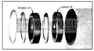
- Lubricate the seals thoroughly with petroleum jelly and install seals with Installer J-6219. Install the single lip seal first, then a back-up washer. Drive seal in far enough to provide clearance for the other seal, back-up washer and retaining ring. Make sure that the inner seal does not bottom on the end of the counter bore. Install the double lip seal and the second back-up washer. Drive outer seal and back-up washer in only far enough to provide clearance for the retaining ring. See Figure 8-24.
- Fill reservoir to proper level, start engine and turn wheel to right and check for leaks.
- Remove tape and reinstall pitman arm.
Removal of 1958 Buick Power Steering Gear
- Place fender cover over left front fender.
- Disconnect the pressure and return line hoses at the 1958 Buick power steering gear and elevate ends of the hoses higher than pump to prevent oil from draining out of pump.
- Mark upper and lower steering shaft flanges for correct assembly. Then disconnect the flexible coupling. See figure 8-17.
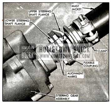
1958 Buick Marking Flexible Coupling
NOTE: Upper ends of both the worm shaft and the upper steering shaft are marked in the “6 o’clock” location when the gear is in the straight ahead position.
Installation of 1958 Buick Power Steering Gear Assembly
- Install the gear assembly by reversing the procedure for removal.
- Fill the reservoir with Dynaflow oil (engine stopped). NOTE: Make sure that all hose connections are tight.
- Start engine to run pump. Maintain proper oil level in the reservoir by adding oil as required.
- When oil level remains constant, rotate the steering wheel through its entire range slowly a few times.
- Recheck oil level, and replace reservoir cover.
Removal, Installation and Bleeding of Oil Pump
- When removing the pump, use shipping plugs and caps to cover the hose connectors and unions on pump and plug open ends of the pressure and return line hose to avoid entrance of dirt.
- When pump is installed on mounting bracket, adjust drive belt tension by using a torque wrench applied to the pulley nut. With a new belt, the tension should be set so that the pulley will slip in belt when 40-45 ft. lbs. torque is applied to pulley nut. With a used belt the torque should be 30-35 ft. lbs.
- Fill the reservoir to proper level with specified Dynaflow oil. Start engine to run pump. Maintain oil level in reservoir by adding if necessary.
- When oil level remains constant, jack up front end of car and rotate the steering wheel through its entire range slowly a few times without causing power assistance. Stop engine, let car down, check oil level and correct if necessary and replace reservoir cover.
8-13 ADJUSTMENT OF 1958 BUICK PITMAN SHAFT AND STEERING LINKAGE
Adjustment of Pitman Shaft with 1958 Buick Power Steering Gear in Car
- Disconnect pitman arm from intermediate tie rod and check tightness of pitman arm nut with an 18″ wrench.
NOTE: Never attempt to adjust 1958 Buick power steering gear with pitman arm connected to intermediate rod. - Turn steering wheel slowly through its full travel to check for binding, tight spots or uneven action.
- Turn steering wheel to extreme right or left position. Apply Scale J-544-A to a spoke at rim of wheel and, while pulling scale at 90 degrees to spoke, check the pull required to turn the wheel steadily in the range where lash normally exists between ball nut and pitman shaft sector. The lash range exists for one eighth turn of steering wheel from either extreme position.
- The reading on the scale should be between 1/4 and 1/2 pound, which would indicate normal loading or drag at the thrust bearing.
- Loosen pitman shaft adjusting screw lock nut and turn adjusting screw counterclockwise a few turns.
- Check the pull required to turn the wheel through the “high-point” or no lash range. The reading should be 1/4 to 3/4 lb. higher than previous reading, which would indicate normal ball nut preload.
- If readings are not within specifications, remove 1958 Buick power steering gear and recheck adjustment on bench as outlined in paragraph 8-13 (b).
- If readings are within specifications, turn pitman shaft adjusting screw clockwise as required to obtain a scale reading 1/2 to 1 pound higher than was obtained in step 6. This reading is taken when pulling wheel through “high-point” with lock nut tight. Total reading should be between 1 1/4 to 1 3/4 lbs.
Adjustment of Pitman Shaft with 1958 Buick Power Steering Gear Removed
Adjustment of pitman shaft can also be made on bench with 1958 Buick power steering gear completely assembled.
- Place 1958 Buick power steering gear assembly in vise with wormshaft up. See Figure 8-18. Install Over Center Adjuster J-6281 on flexible coupling.
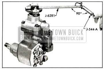
1958 Buick Pitman Shaft Adjustment
This reading is taken when pulling the Over Center Adjuster through “high-point” range with lock nut tight. Total reading should be 1 1/4 to 1 3/4 lbs.
Adjustment of 1958 Buick Steering Linkage
1958 Buick steering linkage adjustments for manual and power steering are the same with one exception.
On the 1958 Buick power steering linkage, the pitman arm end plug adjustment is made in the same manner as idler arm end.
Refer to paragraph 8-4 (b) for steering linkage adjustment.
8-14 DISASSEMBLY, INSPECTION, ASSEMBLY OF 1958 BUICK CONTROL VALVE ASSEMBLY
Removal of 1958 Buick Control Valve Assembly
- Thoroughly clean exterior of gear assembly with a suitable solvent and drain the unit by placing control valve down and turning the worm shaft through its entire range two or three times.
- Remove the control valve retaining bolts and lift control valve and linkage cover off the gear housing. Pull the linkage cover out of the valve body. See Figure 8-19.
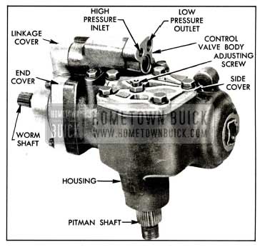
1958 Buick Right Side of Power Steering Gear Assembly
Disassembly of 1958 Buick Control Valve Assembly
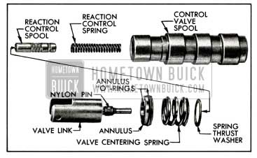
NOTE: Disassembly of the valve spool assembly should normally not be performed unless there is evidence of faulty operation. The valve link contains a nylon pin located in the threaded part. This pin acts as a lock and prevents the valve spool from threading itself out of the valve link. The locking action of this pin will be lost after more than one or two disassemblies.
- Remove annulus retaining snap ring using No. 1 Truarc Ring Pliers J 5403 and annulus retaining washer. Then slide spool assembly out of the valve body. Care should be taken to see that neither the spool assembly or the valve body are scratched or dropped. See Figure 8-20.
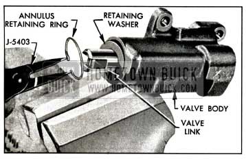
1958 Buick Removing Annulus Retaining Snap Ring
1958 Buick Removing Valve Link
Inspection of 1958 Buick Control Valve Assembly
- Inspect inside of valve body and both spools for scores, nicks, or burred edges. If either the valve body or one of the spools is damaged, a complete control valve assembly must be replaced as the valve body and spools are selective fits and therefore are available only as an assembly.
- Inspect the hose connectors. If badly brinelled or scored, replacement will be necessary. To remove the connectors, tap threads in the hole using a 5/16-18 tap in the large connector and a No. 12-24 tap in the small connector. Pull the connector by using a bolt threaded into the tapped hole and a flat washer and nut as an extractor. Wash and blow the valve body out thoroughly to remove any tapping chips. To replace the connector, use Replacer J 6217 to drive the connector in place.
Reassembly of 1958 Buick Control Valve Assembly
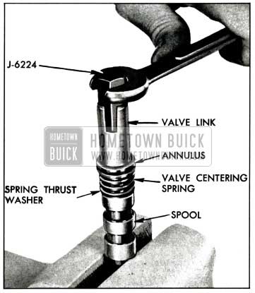
- Thoroughly clean all the parts and lubricate the internal parts with Dynaflow oil. Then clamp spool in vise in same manner as in disassembly, and install reaction control spring and spool with narrow land next to spring. Assemble spring thrust washer and valve centering spring on the spool. Lubricate new annulus O-ring seals with petroleum jelly and install on annulus. Assemble annulus on spool with narrow land of annulus toward spring.
- Hold annulus down on spool to compress the spring. Then assemble link and tighten to 8-10 ft. lbs. using Remover and Replacer J 6224. See Figure 8-22.
1958 Buick Control Valve Spool Assembly
Remove the spool assembly from vise. Carefully insert the spool assembly into the valve body. The spool and valve body are selective fits and have very little clearance. Only if properly started can the spool be assembled. DO NOT ATTEMPT TO FORCE THE SPOOL INTO THE VALVE BODY.
Installation of 1958 Buick Control Valve Assembly
- Lubricate new linkage cover O-ring seal and install on linkage cover. Assemble linkage cover to control valve. Position valve link so that slot is perpendicular with the bottom of valve.
- Install the two small new O-ring seals on gear housing and new O-ring seal on end cover. Position control valve and linkage cover over gear housing and end cover. Start actuating lever into the link slot and then push down on the linkage cover until the valve is seated on the housing.
- Install control valve retaining bolts and tighten to 15-20 ft. lbs. Tighten the bolt on lower end of control valve first. BE SURE NOT TO FORCE THE VALVE IN EITHER DIRECTION WHILE TIGHTENING BOLTS AS THIS WILL CAUSE MALFUNCTIONING OF THE VALVE.
8-1 5 DISASSEMBLY, INSPECTION, ASSEMBLY OF 1958 BUICK PITMAN SHAFT ASSEMBLY
Removal of 1958 Buick Pitman Shaft Assembly
- Remove control valve assembly as outlined in Paragraph 8-14 (a).
- Remove side cover retaining bolts and rotate cover one-half turn. Align pitman gear with opening in gear housing by turning worm shaft. Tap the end of pitman shaft with a soft mallet and remove pitman shaft from housing.
Disassembly of 1958 Buick Pitman Shaft Assembly
- Hold pitman shaft adjusting screw with an Allen head wrench and remove adjusting screw locknut and discard. Turn the screw out of cover and remove cover. Cut off or push up staked portion of lash adjusting screw retainer. Remove retainer and adjusting screw and discard both. A nylon pin in the adjusting screw prevents any loss of fluid past the threads. Whenever the adjusting screw is removed this pin is damaged and a new adjusting screw should be installed. Remove adjusting screw washer from bore in pitman shaft.
- Remove the pitman shaft seal retaining snap ring from end of housing using No. 3 Truarc Pliers J 4245 and seal back-up washer. To remove shaft oil seals, tap an offset screw driver in between seals and shoulder in gear housing, then pry seals out of housing being careful not to damage the seal bore in housing. NOTE: It is recommended to use the method outlined in Paragraph 8-12(a) for removal of pitman shaft seal.
Inspection of 1958 Buick Pitman Shaft Assembly
- Inspect pitman shaft bearing surface in side cover for excessive wear or scoring. If worn or scored replace side cover.
- Check pitman shaft sector teeth and bearing surfaces. If worn, pitted, or scored, replace shaft. Then check the pitman shaft bore in housing for wear. If worn, the housing should be replaced.
Reassembly of 1958 Buick Pitman Shaft Assembly
- Place adjusting screw washer in bore in pitman shaft, lubricate head end of new adjusting screw with petroleum jelly and place it in bore.
- Install new adjusting screw retainer, turning it down so adjusting screw is free to turn, but has no perceptible end play. Stake retainer securely into slot in pitman shaft in two places. See Figure 8-23.
1958 Buick Lash Adjusting Screw
Installation of 1958 Buick Pitman Shaft Assembly
- Turn worm shaft as necessary until the center groove of the rack-piston is aligned with center of pitman shaft bushing. Install pitman shaft so that the center tooth in the sector meshes with the center groove of rack-piston. Make sure that new side cover O-ring is in place, then push the side cover down on gear housing.
- Install and tighten the four 3/8″ side cover bolts to 25-30 ft. lbs. Install and tighten the 5/16″ side cover bolt to 15-20 ft. lbs. Then install adjusting screw lock nut.
- To prevent damage to pitman shaft oil seals, fully cover pitman shaft splines with tape. Use only a single layer of tape.
- Lubricate the seals thoroughly with petroleum jelly and install as per paragraph 8-12 step 7. See Figure 8-24.
1958 Buick Pitman Shaft Seal Assembly
8-16 DISASSEMBLY, INSPECTION, ASSEMBLY OF 1958 BUICK RACK-PISTON AND WORM ASSEMBLY
Removal of 1958 Buick Rack-Piston and Worm Assembly
- Remove control valve assembly as outlined in Paragraph 8-14 (a) and 1958 Buick pitman shaft as outlined in Paragraph 8-15 (a).
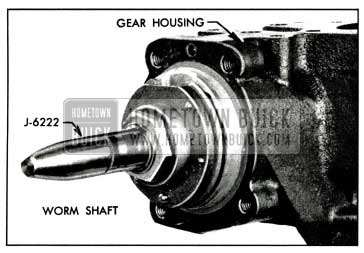
- Pull actuator lever out of end cover and remove flexible coupling and mark coupling flange and worm shaft before disassembly. Support coupling flange and remove coupling flange and felt washer from worm shaft by driving pin out with punch. See Figure 8-25.
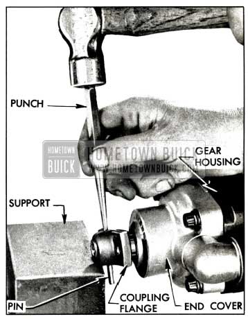
1958 Buick Removing Coupling Flange
1958 Buick Removing Rack-Piston and Worm Assembly
Disassembly of 1958 Buick Rack-Piston and Worm Assembly
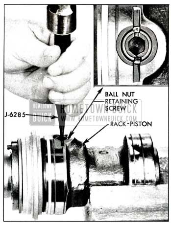
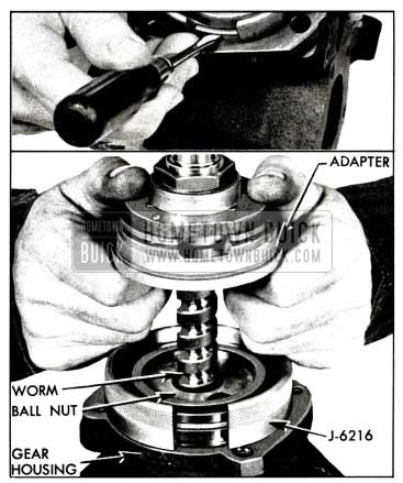
- Remove piston ring from rack-piston. Unstake and remove ball nut retaining screw using Allen wrench and slide the ball nut and worm assembly out of rack-piston with ball nut retaining screw hole down to prevent ball return guides from falling out and losing balls.
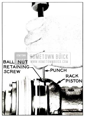
1958 Buick Unstacking Ball Nut Retaining Screw
1958 Buick Removing Balls from Ball Nut
Inspection of 1958 Buick Rack-Piston and Worm Assembly
- Inspect the worm and ball nut grooves and all the balls for wear or scoring. If either the worm or ball nut needs replacing, both must be replaced as a matched assembly.
- Inspect ball return guides, making sure that the ends where the balls enter and leave the guides are not damaged.
- Inspect the rack-piston teeth for pitting, wear, and scoring. Inspect all bearing surfaces on rack-piston for scoring. Do not remove rackpiston end plug unless it is loose. To replace plug, drive old plug out from inside rack-piston, press new plug in flush with end of rack-piston and stake securely in four places. Inspect retaining screw threads in rack-piston and tap out if necessary.
- Inspect housing bore. If badly scored or worn, replace housing. Inspect housing end plug for leakage. Unless there is visual evidence of leakage, do not remove end plug. To remove end plug, the staked portion must be either pushed up or cut off so that the plug may be driven into the housing without scoring the sealing diameter. To replace the end plug, lubricate a new plug O-ring seal and install on a new end plug. Install end plug in housing from the inside and stake plug securely in four places. Inspect the pitman shaft bore and if badly worn, replace housing.
- Inspect the thrust bearing centering springs. If any of the four springs riveted to the thrust bearing are broken, the thrust bearing assembly must be replaced. If any of the four loose springs are broken, replace all four.
- Check for roughness by holding the worm stationary and rotating the center race. If the bearing is rough, replace thrust bearing assembly. Check the thrust bearing preload. This should be between %, and 3 lbs. measured at the outer edge of the center bearing. To measure bearing preload, clamp the worm in a vise using soft jaws. Fasten a cord to one of the riveted centering springs and wind it around the center race. Attach the other end of the cord to Spring Scale J-544-A. Then slowly pull the other end of the scale and check the reading. If the preload is not within the limits, push the staked portion of the thrust bearing nut up out of the thread groove, being careful not to damage the thread, and remove the nut and discard. Use a new nut and .adjust as necessary to obtain proper preload. After the proper preload has been obtained recheck bearing for roughness and stake the nut being careful not to move the nut when staking. Recheck the preload after staking. See Figure 8-29.
1958 Buick Checking Thrust Bearing Preload
1958 Buick Installing End Cover Needle Bearing
Reassembly of 1958 Buick Rack-Piston and Worm Assembly
- Thoroughly clean, oil the parts, and lubricate the internal parts with Dynaflow oil. Use only new seals and gaskets during assembly.
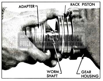
- Lubricate O-ring and install on adapter. Lubricate and install adapter oil seal with black rubber side out, then install seal back-up washer and retaining ring. Assemble adapter to worm being careful not to damage the seal when passing over the worm grooves. Slide the ball nut with the chamfered edge away from the adapter over the worm up to the adapter.
- Align the ball return guide holes with the worm groove. Load 16 balls into the ball nut (8 plain balls and 8 black balls) in alternate sequence. Drop the balls into the return guide hole farthest from adapter while slowly rotating the worm counterclockwise to feed the balls through the circuit. After the balls are completely loaded, one black ball and one plain ball will be visible in the ball nut guide holes.
NOTE: When the ball nut is completely loaded with 16 balls (8 black and 8 plain), enough area in the ball nut guide hole is visible to insert another ball, but under no circumstances should an extra ball be installed.
1958 Buick Loading Balls in Ball Nut
- Fill one-half of the ball return guide with the remaining 6 balls (3 plain balls and 3 black balls) in alternate sequence. Place the other half of the guide over the balls and plug each end with heavy grease to prevent the balls from falling out when installing the guide into the ball nut.
- Insert guide into guide holes of the ball nut so that balls in the guide alternate with balls in the ball nut. Guide should fit loosely. Wrap a strip of tape around the ball nut and guide to prevent the guide from falling out.
- The worm groove is ground with a high point in the center. When the ball nut passes over this highpoint, a preload of 1 to 4 1/2 inch pounds should be obtained. To measure the preload of the ball nut, lightly clamp the ball nut in a bench vise, using soft jaws. Do not distort the ball nut by tightening too heavily. Rotate the worm until its end projects out of the nut 1 7/8 inches.
This is the center position. Attach a torque wrench with 3/4 inch, 12 point socket to the splined end of the worm. Oscillate the wrench through a total arc of approximately 60° in both directions several times and take a reading. The high reading with the worm rotating reading is too high disassemble and reassemble, using the next size smaller plain balls, and recheck. (A ball nut with the ball size of 7 does not have a number stamped on the round surface. For ball sizes other than 7, the ball size is stamped on the round surface of the ball nut.) If the reading is too small, use the next size larger plain balls and recheck.
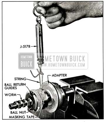
1958 Buick Checking High Point Preload
NOTE: Because the size of the black ball is constant, only the plain ball size need be changed to increase or decrease preload readings.
- Install steel washer, Teflon seal with rubber toward worm, bronze back-up washer, retaining ring washer, and seal retaining ring on end of worm. Then lubricate the Teflon seal with Dynaflow oil. See Figure 8-33.
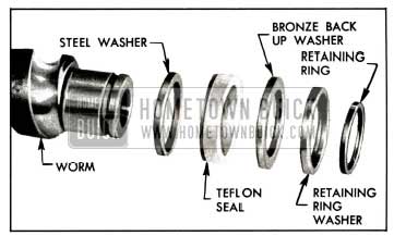
1958 Buick Worm Seal Assembly
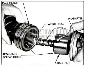
1958 Buick Installing Worm Assembly in Rack-Piston
1958 Buick Staking Ball Nut Retaining Screw
1958 Buick Installing Rack Piston with Teflon Ring
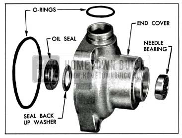
1958 Buick End Cover Bearing and Seal Assembly
1958 Buick Seal Protector Installed on Worm Shaft
8-17 DISASSEMBLY, INSPECTION, ASSEMBLY OF 1958 BUICK SAGINAW OIL PUMP
Disassembly of 1958 Buick Saginaw Oil Pump
- Use shipping caps to cover the hose unions on pump to exclude dirt, then thoroughly clean exterior of pump.

1958 Buick Compressor-Pump Assembly Mounting
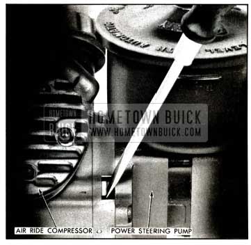
NOTE: To remove the oil pump on models equipped with Air-Poise suspension, disconnect compressor pump assembly rear mounting bracket from intake manifold and left cylinder head. Then remove two bolts and carefully separate oil pump from compressor. (If difficulty is encountered, insert screwdriver between bolt recess on compressor and pump body, then carefully pry apart.) See Figure 8-40.
1958 Buick Separating Pump and Compressor
- Remove reservoir cover, drain out all oil and remove filter screen and filter retainer by pulling the retainer. See Figure 8-41 and 42.
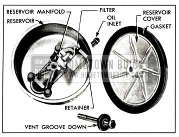
1958 Buick Reservoir with Cover Removed – Standard Pump
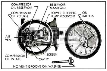
1958 Buick Reservoir with Cover Removed – Air Poise Pump
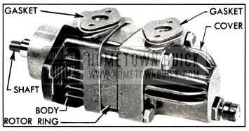
1958 Buick Pump with Reservoir Removed
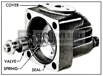
1958 Buick Pump Cover and Control Valve
NOTE: Air Poised Equipped Cars-To remove and install oil seal in pump body, it is not necessary to disassemble pump.
NOTE: On standard equipped cars, the reverse is true.
- Remove pump seal, using Remover J-5822 installed on suitable slide hammer. See figure 8-45 (standard pump) and figure 8-46 (Air Poise Pump).
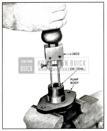
1958 Buick Removal of Drive Shaft Seal – Standard Pump
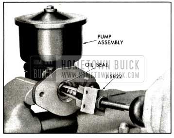
1958 Buick Removal of Drive Shaft Seal – Air Poise Pump
CAUTION: When removing pump seal, care must be taken so that the upper bushing (standard pump) and seal shoulder (Air Poise pump) are not damaged.
- Remove pump shaft from front of body (standard pump only) and disassemble pump.
- If babbit bushings in pump body are worn, replace body. If shaft is worn or damaged, replace shaft.
Inspection of 1958 Buick Saginaw Pump Parts
- Clean shaft with solvent. Wipe dry with clean lint free cloth and inspect shaft for wear.
- Inspect the drive shaft for wear and check the ball bearing for roughness or noisy operation. If the ball bearing must be replaced, press the new bearing on shaft with a tool that applies pressure on the inner race only.
- Check fit of vanes in slots of rotor; vanes must slide freely but fit snugly in slots. Tightness may be relieved by thorough cleaning or removal of irregularities using Arkansas stone. Replace rotor if excessive looseness exists between rotor and vanes, and replace vanes if they are irregularly worn or scored.
- Inspect all ground surfaces of the rotor ring for roughness or irregular wear. Slight irregularities may be removed with a hard Arkansas stone. Replace ring if inside cam surface is scored or worn.
- Inspect the flat faces of the pressure plate and body for wear or scoring. These faces may be repaired by lapping until smooth and flat, after which all lapping compounds must be thoroughly washed away.
- Inspect the control valve bore in pump cover for scores or other damage. Hair line scratches are normal but heavy scratches or scores should be cleaned up with a cylindrical hard Arkansas stone. If this cannot be done satisfactorily, replace the cover.
- Inspect ground surfaces of the control valve for scores. Hair line scratches are normal but heavy scratches or scores should be cleaned up with a hard Arkansas stone. Replace the valve assembly if it is a badly scored or if it is found to be the cause of low pump pressure. It is not practicable to disassemble the control valve. Make certain that control valve slides freely in bore of pump cover.
The outer and inner bushings in the pump body are not serviced. If either is damaged, the body must be replaced.
Assembly of 1958 Buick Saginaw Pump
Assemble the pump by reversing procedure for disassembly, paying attention to the following items:
- Make sure that all parts are absolutely clean, and lubricate all moving parts with clean Dynaflow oil during assembly.
- Use new seals and gaskets as required.
- Make certain the shaft seal is firmly seated in its proper position. The shaft seal must be installed so that the side to which the spring is attached is toward the rear of the pump. Immerse the seal in Dynaflow Oil before installation.
- Using Installer 7017 (standard pump) and 7111 (Air Poise pump) drive seal into pump. See Figures 8-47 (standard) and 8-48 (Air Poise Pump).
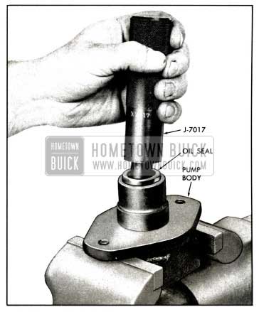
1958 Buick Installation of Drive Shaft Seal – Standard Pump
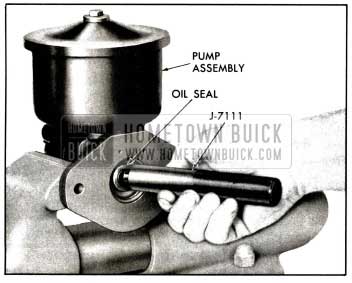
1958 Buick Installation of Drive Shaft Seal – Air Poise Pump
NOTE: When viewed from the front or shaft end of pump, the arrow on the ring points in a clockwise direction, which is the direction of rotation of pump shaft.
- Install vanes in slots of rotor with the rounded edge outward toward the ring. The rotor is installed with the chamfered end of its splines toward the pump body (all models).
- When pump cover is installed turn bolts down to 25 to 30 foot pounds torque. Install reservoir with new gaskets, then tighten to 8 to 10 ft. lbs. torque. Install filter spring (on Air Poise Reservoirs only), filter retainer, and filter.
- When installing pump to compressor, install 2 guide pins J7003 (%-16 x 3) in bolt attaching holes in compressor and carefully install pump over guide pins. Care must be used to prevent the compressor crankcase splines from damaging the oil seal in the pump body. Remove guide pins and install attaching bolts and tighten to 25-30 ft. lbs. torque.
NOTE: If pump does not seat properly against compressor, hold pump firmly and remove guide pins. Then rotate pump slightly while applying pressure at rear of pump.
- When assembly is completed, rotate pump shaft to insure free movement.
- After pump is installed on car and belt tension is adjusted, fill reservoir to the oil level line with Dynaflow oil. Install reservoir cover, washer, and torque bolt to 7-9ft. lbs.