SECTION 10-G 1958 BUICK LIGHTING SYSTEM
10-47 1958 BUICK HEADLIGHTS AND CONTROLS
Description of 1958 Buick Lighting Switch
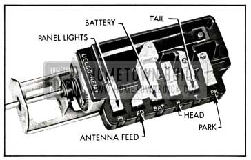
The switch has push-in-type wire terminals. Each terminal on the switch is color-coded to match the color of the wire. It is a “push-pull” type which also incorporates a manually operated rheostat for controlling the instrument panel lights. Three “push-pull” positions of the switch knob provide control of the 1958 Buick exterior lights as follows:
- “Off” position (knob all the way in) cuts off all 1958 Buick lights controlled by the switch.
- “Parking” position (knob pulled out to first notch) turns on the 1958 Buick parking lights, 1958 Buick tail lights, and license light and key light. The instrument panel lights also will be turned on if the rheostat is set for these 1958 Buick lights.
- “Driving position (knob pulled out to last notch) turns parking lights off and turns headlights on, while the other lights remain as in the “Parking” position. The 1958 Buick headlights will be on the “upper” or “lower” beams depending on the position of the separate dimmer switch.
In the “Parking” and “Driving” positions, the 1958 Buick instrument panel lights are controlled by rotating the light switch knob. With the knob turned all the way counterclockwise, these lights are on maximum brightness. As the knob is turned clockwise, they gradually dim until they are off at the full clockwise position of the knob.
Description of 1958 Buick Thermo Circuit Breaker
A 1958 Buick thermo circuit breaker is incorporated in the 1958 Buick lighting switch assembly, to protect wiring from damage due to short circuits in any lighting circuit controlled by the switch.
The thermo circuit breaker consists of a bimetal blade and set of contact points connected in series with the 1958 Buick lighting circuits. An abnormal flow of current through the circuit breaker, such as would be caused by a short circuit in a 1958 Buick lighting circuit, heats the bi-metal blade sufficiently to separate the points and cause them to vibrate. The vibrating blade alternately opens and closes the circuit, thus reducing the flow of current and protecting the wiring against overheating and burning. The flickering light produced by the vibrating circuit breaker serves as a warning to the operator of vehicle that a short circuit exists.
Test of 1958 Buick Lighting Switch
If the 1958 Buick lighting switch is suspected of being faulty, the contacts can be tested by connecting a short jumper wire between the switch “BAT” terminal and the other terminals while observing any change in the brilliance of 1958 Buick lights affected. See figure 10-48.
1958 Buick Lighting Switch
With switch in “Parking” position (first notch out) connect jumper wire between “BAT” and “PK” terminals and note change in 1958 Buick parking lights. Bridge between “BAT” and terminals and note change in 1958 Buick tail lights. With switch in “Driving” position (last notch out) bridge between “BAT” and “H” terminals and note change in headlights.
If no change in brilliance of 1958 Buick lights is noted the switch contacts are satisfactory and the cause is in the wiring circuit connections or lamp bulb. If switch is faulty it must be replaced since internal repairs cannot be made.
Replacement of 1958 Buick Lighting Switch
- Disconnect battery cable from junction block and disconnect wires from 1958 Buick lighting switch.
- Pull switch knob out to last notch, then depress the spring loaded latch button on switch while pulling the knob and rod assembly out of switch. NOTE: If latch button is depressed before switch knob is pulled out, knob and rod assembly will not release.
- Remove switch mounting nut with Wrench J-1589-A and remove switch and escutcheon from instrument panel. See figure 10-48.
- When installing 1958 Buick lighting switch, connect wires according to color codes as shown on chassis wiring circuit diagrams in Section 10-J. When connecting battery ground cable use care to properly wind the clock (par. 10-56).
Test of 1958 Buick Thermo Circuit Breaker
To test the 1958 Buick thermo circuit breaker, remove 1958 Buick lighting switch from instrument panel to avoid possible damage to adjacent instruments.
Since the current required to open the circuit breaker contacts depends somewhat on outside temperature, the circuit breaker should be tested at normal temperature (70° to 80°F.).
- Connect an ammeter and a carbon-pile rheostat in series with the “BAT” terminal of 1958 Buick lighting switch and positive terminal of a 12- volt battery, and set rheostat to provide maximum resistance. Rheostat must have capacity for 50 amperes and be adjustable down to .3 ohms.
- With switch on, connect the “H” terminal of 1958 Buick lighting switch to negative post of battery.
- Adjust rheostat to give 42 amperes. The circuit breaker should open within 30 to 60 seconds.
- Adjust rheostat to give 22.5 amperes on ammeter. The circuit breaker should remain closed indefinitely at 22.5 amperes.
- If circuit breaker does not operate as specified the 1958 Buick lighting switch assembly should be replaced. The circuit breaker is not adjustable and no attempt should be made to alter the calibration by bending the bi-metal blade. The contact points must not be filed or sanded.
1958 Buick Dual Headlamp Assembly
The 1958 Buick dual headlamp system is standard equipment on all series and consists of two dual headlamps, one mounted on each side of the car.
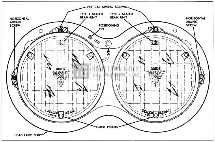
Each 1958 Buick dual headlamp includes two 5 3/4″ T-3 sealed beam units mounted in a single housing enclosed by one headlamp door. The indoard unit is used for bright lights only and has a single filament. The outboard unit is used for both bright and dim lights and has two filaments. For identification, the inboard unit is marked “1,” the outboard unit is marked “2”. See Figure 10-49.
1958 Buick Left Dual Headlamp Assembly
When the 1958 Buick dimmer switch is in the dim or lower beam position only, the outboard (type “2”) unit of each dual headlamp is on. Both outboard (type “2”) and inboard (type “1”) units of each dual headlamp are on when the dimmer switch is in the bright or high beam position.
The T-3 sealed beam unit has three projections equally spaced around the perimeter of the lens. These projections are ground off at the factory to provide a mounting surface for the Guide T-3 Safety-Aimer. This aiming device is used without switching 1958 Buick headlights on as described below (par 10-48, d).
1958 Buick Dimmer Switch
The driver may select the upper or lower headlight beam as traffic and road conditions demand by operating the dimmer switch mounted on the toe panel in a convenient position for the left foot.
The dimmer switch opens and closes the circuits to the upper and lower lamp filaments in both sealed beam units, thereby alternately raising and lowering the 1958 Buick headlight beams with each successive operation of the switch. Depression of switch button turns the rotary contacts one position within the switch. The springloaded button automatically returns to the reset position when released.
1958 Buick Headlight Beam Indicator
Whenever the upper headlight beams are lighted, a beam indicator bulb on the instrument panel also lights, producing a small spot of red light in front of the driver. For safety reasons, he should never pass an approaching car with the beam indicator showing red.
10-48 1958 BUICK HEADLAMP SEALED BEAM UNIT – REPLACEMENT AND ADJUSTMENT
Replacement of 1958 Buick Sealed Beam Unit
When a sealed beam unit is burned out or broken it must be replaced as a unit assembly.
- Remove headlamp door.
- Unhook the spring from retainer ring, then remove sealed beam unit and retainer ring, being careful not to disturb the two beam adjusting screws.
- Separate the sealed beam unit from the wiring connector.
- Spring the retainer ring slightly where marked “TOP” to remove mounting ring and sealed beam unit.
- Install new sealed beam unit by reversing removal procedure. Position lens with the “1” or “2” up. The reflector has three lugs which fit into notches in the headlamp mounting ring.
CAUTION: Make sure that sealed beam unit is marked “1” for an inboard unit or “2” for an outboard unit.
- Before installation of headlamp door, adjust headlamp for proper aim as described below.
1958 Buick Headlamp Aiming
The 1958 Buick headlamps must be properly aimed in order to obtain the maximum road illumination and safety that has been built into the 1958 Buick headlighting equipment. With the Guide T-3 type sealed beam units, proper aiming is even more important because the increased range and power of this new lamp make even slight variations from recommended aiming hazardous to approaching motorists. The headlamps must be checked for proper aim whenever a sealed beam unit is replaced and after any adjustment or repairs of the front end sheet metal assembly.
Regardless of method used for checking headlamp aim, car must be at curb weight, that is, with gas, oil, water, and spare tire, but no passengers. Tires must be uniformly inflated to specified pressure (par. 1-1). If car will regularly carry an unusual load in rear compartment, or a trailer, these loads should be on car when headlamps are checked. Some states have special requirements for headlamp aiming adjustment and these requirements should be known and observed.
Horizontal and vertical aiming of the 1958 Buick headlamp beam is provided by the two beam adjusting screws which move the mounting ring in the body against the tension of the coil spring. There is no adjustment for focus since the sealed beam unit is set for proper focus during manufacturing assembly.
Use of Guide 1958 Buick Headlamp Aimer
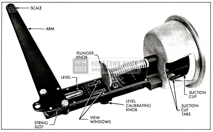
The Guide T-3 Safety Aimer makes it possible to precision-aim 1958 Buick’s dual headlamp system in a minimum amount of time and space and to check the aim of the headlamps without removing the headlamp doors.
No screens or other aiming equipment are needed and aiming can be accomplished in daylight or darkness without the headlamps turned on. An average stall is all that is required since only sufficient room is needed for a man to walk around the car. A stall with a level floor is preferred so that aimer can be used just as received from the factory without being recalibrated.
The T-3 Aimer comes from the factory with level bubbles accurately set and instructions for rechecking the level accuracy after aimer has been in use. It is important that these instructions be followed when aimer is received and before it is used, as a precaution in case aimer is dropped or damaged. The aimer can be used in selecting an area for headlamp aiming and can be calibrated to compensate for uneven floors. The procedure for checking and adjusting headlamp aim is the same on all coil spring and Air-Poise equipped cars.
The Guide T-3 Safety Aimer for the lefthand dual headlamp is shown in figure 10-50.
1958 Buick Left T-3 Headlamp Aimer
Mounting Aimer for Checking Aim
NOTE: It is not necessary to remove 1958 Buick headlamp doors to check headlamp aim.
- Drive the car onto the selected aiming area.
IMPORTANT: For an accurate headlamp aim the floor must either be level or else the T-3 Safety Aimer must be calibrated for the selected aiming area in accordance with instructions received with aimer. Once the aimer is calibrated for an unlevel floor, all future aimings MUST be made with cars placed on the same area faced in the same direction.
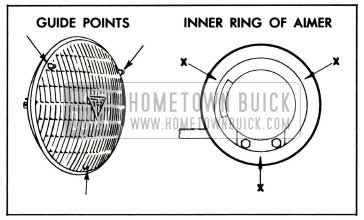
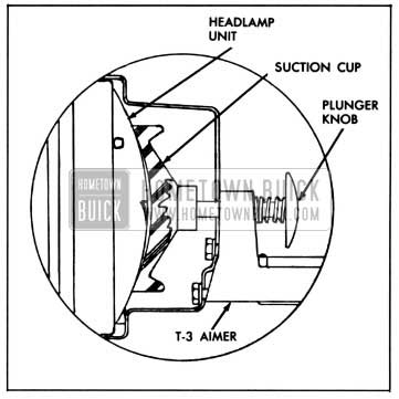
- Mount the T-3 Safety Aimers on each of the inboard units (type “1”) so that the lamp guide points engage smooth inner ring of aimer at points “X” and the arm on each aimer points toward center of car. See Figure 10-51.
1958 Buick Positioning Headlamp Aimer
1958 Buick Attaching Aimer
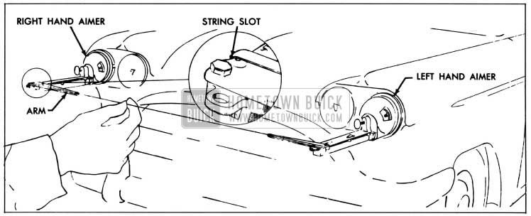
1958 Buick Positioning String
Checking Horizontal Aim
- The string should cross between right and left line “2” on scale of aimer. If the string does not fall within these limits it is necessary to adjust horizontal aim using procedure in subpar. h.
- Check horizontal aim of other type “1” unit as instructed above.
Checking Vertical Aim
- The bubble should be within the two outside lines of the level on the aimer. If bubble in level does not fall within these limits it is necessary to adjust vertical aim using procedure in subpar. i.
- Check vertical aim of other type “1” unit as instructed above.
- Remove aimers by pulling on the suction cup tabs through opening in aimer. Mount the aimers on each of the outboard units (type “2”) and check head lamp aim of the type “2” units as instructed in above sub. pars. d, e and f.
Mounting Aimer for Adjusting Aim
- Remove the headlamp doors and replace any defective unit.
- Mount T-3 aimers on Type “1” units as instructed in subpar. c above.
Adjusting Horizontal Aim
- Turn horizontal aiming screw on lefthand unit until the string is positioned directly over the center line of the scale on the lefthand aimer. Turn screw clockwise in making final adjustment to take up play in the headlamp mechanism. See Figure 10-54.
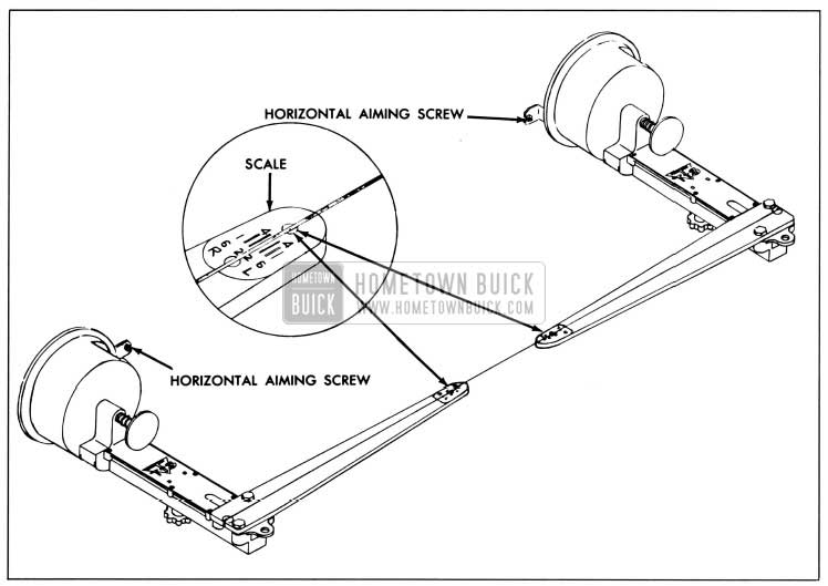
1958 Buick Adjusting Horizontal Headlamp Aim
Adjusting Vertical Aim
- Turn headlamp vertical a1mmg screw counter-clockwise until the bubble in level is at the end of vial toward headlamp unit. Then turn screw clockwise until bubble is centered in the level. See Figure 10-55.
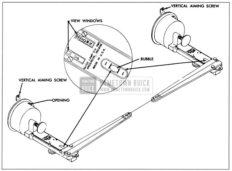
1958 Buick Adjusting Vertical Headlamp Aim
10-49 1958 BUICK AUTRONIC-EYE AUTOMATIC HEADLAMP CONTROL
General Description
The 1958 Buick Autronic-Eye is an electronic device that automatically switches the headlamps between the upper and lower beams in response to light from approaching cars. The electrical power to operate the 1958 Buick Autronic-Eye comes from the headlight terminal of the regular light switch and it is therefore energized whenever the light switch knob is pulled fully out. Overload protection is provided by the regular thermo circuit breaker on the light switch.
The 1958 Buick Autronic-Eye consists of four separate units: a power relay, a combination dimmer override foot switch, an amplifier, and a phototube. See figure 10-57.
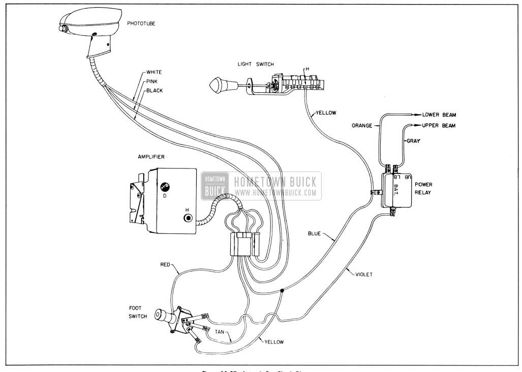
1958 Buick Autronic-Eye Circuit Diagram
The power relay, mounted in the engine compartment, is a heavy duty relay which switches the headlamps between the upper and lower beams. It switches the 1958 Buick headlamps to the lower beam when the relay control signal from the amplifier is of sufficient strength to actuate the relay (this circuit goes to ground in the relay). See figure 10-57. When the signal from the amplifier is too weak to actuate the relay, a spring in the relay switches the headlamps to upper beam.
The foot switch, mounted in the toe pan at the far left, has two ratchet positions plus a special override section. The two regular positions are automatic and lower beam. The headlamps are controlled by the 1958 Buick Autronic-Eye in the automatic position only; in the lower beam position, the headlamps are mechanically locked on the lower beam. See figure 10-57.
The override section of the foot switch functions only when the switch is in the automatic position. A slight pressure on the top of the switch provides upper beam, regardless of the amount of light on the phototube. Upper beam is obtained by temporarily grounding the amplifier signal inside the foot switch; with no signal available for the power relay control circuit, the relay switches to upper beam. This arrangement permits signaling, if desired, and provides a simple test for the automatic position of the foot switch.
The amplifier, mounted on the forward side of the left front door hinge pillar behind the kick panel, supplies voltage to energize the phototube. It receives and amplifies any signal from the phototube. If the signal is weak, the amplifier signal to the power relay control circuit is correspondingly weak and the relay will not be actuated; if this signal is strong, the amplifier signal to the power relay is also strong and the relay will be actuated.
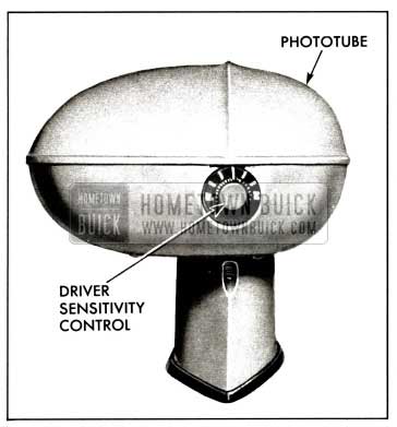
The phototube, mounted on the top left side of the instrument panel, is energized by voltage supplied by the amplifier. It is an optical device which picks up light from ahead of the car and converts this light into an electrical signal which is supplied to the amplifier. The sensitivity of the phototube is adjusted to compensate for the different amount of light coming through a clear or a tinted windshield. A driver sensitivity control, located at the rear of the phototube, provides the driver with a limited sensitivity adjustment. See Figure 10-56.
1958 Buick Autronic Eye Phototube
Operation
In the automatic position of the foot switch, the 1958 Buick Autronic-Eye provides completely automatic switching of the headlamp beams. When a car approaches within proper distance, light from its headlamps striking the phototube causes the Autronic-Eye to switch the headlamps to the lower beam. At this time, if the approaching car’s headlamps were on upper beam, the driver would normally switch to lower beam which would greatly reduce the amount of light striking the phototube. The 1958 Buick Autronic-Eye is designed to hold its vehicle headlamps on a lower beam even with this reduction in light. When light is removed from the phototube, the Autronic-Eye returns the 1958 Buick headlamps to upper beam.
If the approaching vehicle fails to switch to lower beam, the override section of the foot switch may be operated to provide an upper beam for signaling purposes.
Street lights and other lights encountered in the city are sufficient to cause the 1958 Buick Autronic Eye to hold its vehicle headlamps on lower beam.
The 1958 Buick Autronic-Eye is disconnected from its vehicle headlamps in the lower beam position of the foot switch; however, the Autronic-Eye is not turned off. It continues to function as long as the headlamps are turned on, and is ready at all times to provide automatic control whenever the foot switch is returned to automatic position.
A driver control or sensitivity control knob is located at the rear of the phototube. This control gives the driver of the car a certain amount of control over sensitivity. A detent position (knob pointer straight up) is provided or normal sensitivity. Rotating the knob so that “F” is up increases sensitivity, causing the headlamps to switch to the lower beam when an approaching car is farther away than normal. Rotating the knob so that “N” is up decreases sensitivity, causing the headlamps to switch to the lower beam when an approaching car is nearer than normal.
Trouble-Shooting
The 1958 Buick Autronic-Eye is adjusted at the factory and should hold its adjustment over a long period of time. Of course, there may be occasions when the adjustment is questioned. Like any other electrical device, a misunderstanding of the operation of the unit may lead one to believe that an adjustment is necessary. The following trouble may be reported:
- Normal Complaints
- Headlamps switch to the lower beam when an approaching car is too far away.
- Headlamps switch to the lower beam when an approaching car is too close or will not switch to the lower beam at all.
- Headlamps will not return to the upper beam when no car or other lights are ahead.
- Headlamps return to upper beam when the approaching car switches to lower beam.
- Headlamps switch rapidly back and forth between upper and lower beam.
- Checking Operation
While the above complaints may be corrected by simple aiming and sensitivity adjustments in most cases, a few operation checks should be made to determine if the difficulty is more serious than can be corrected by simple adjustment. With the car in a light area, check as described below:
- Pull the light switch knob to full “On” position. After a few seconds warm-up time the lights should remain on the lower beam, regardless of the position of the foot switch.
- Lightly depress the foot switch. The headlamps should switch to upper beam (as shown by upper beam indicator) if the foot switch is in the automatic position. If not, trip the foot switch and again depress to the override section. The lights should now switch to the upper beam. When the override section of the foot switch is released, the headlamps should return to the lower beam.
- Cover the phototube lens tightly with the palm of the hand or with a folded cloth. If the foot switch is in automatic position, the headlamps should switch to the upper beam. When hand is removed, the headlamps should switch back to the lower beam.
If the 1958 Buick headlamps operate as explained in the above checks, the Autronic-Eye should operate correctly after making the adjustments as described in subpar. d below.
If the 1958 Buick headlamps do not operate properly as explained above, the difficulty is more serious than can be corrected by adjustment and the tests in step 3 should be made to isolate the trouble.
- Isolating Trouble
If the Autronic-Eye did not operate properly when checked-out in step 2 above, the following tests should be made to isolate the trouble to either the power relay, the foot switch, or the electronic circuit.
- To test both power relay and foot switch, turn headlamps on and operate foot switch. If headlamps switch between upper and lower beam, power relay and main section of foot switch are okay. Next check all wiring and connections. If wiring is okay, trouble is narrowed down to the phototube or amplifier. See subpar. e.
If headlamps remain on either upper or lower beam when foot switch is operated, test power relay and foot switch as described in subpars. b and c. - To test power relay if it cannot be operated by foot switch, check at power relay as follows:
- Make sure wires are properly connected. See figure 10-57.
- If headlamps stay on lower beam, disconnect violet wire from “C” terminal-headlamps should switch to upper beam.
- If headlamps stay on upper beam, connect “BAT” terminal to “C” terminal with a suitable jumper-headlamps should switch to lower beam.
- If power relay will not operate as described, relay is defective and should be replaced.
- To test main section of foot switch, if power relay is okay, check foot switch as follows:
- Make sure wires are properly connected. Violet wire must be connected to long terminal. See figure 10-57.
- Make sure yellow wire terminal on foot switch is hot. Disconnect tan wire from switch-headlamps should switch between upper and lower beam when foot switch is operated.
- With foot switch in position where headlamps are on upper beam, connect jumper between yellow wire terminal and vacant tan wire terminal-headlamps should switch to lower beam.
If foot switch will not operate as described, switch is defective and should be replaced.
- To test override section of foot switch when headlamps will not flash between upper and lower beam, remove left kick panel. Pull red wire apart at connector and ground terminal of section which comes from amplifier. If headlamps now flash between upper and lower beam, this proves that the override circuit is okay up to the foot switch. Therefore the foot switch must be defective and should be replaced.
- Amplifier and Phototube. If trouble was not in the power relay or in the foot switch, next make sure all wires are properly connected. See figure 10-57. If the Autronic-Eye still will not respond to the operational checks as described in step 2 above, the trouble must be in the amplifier or phototube. These two units should therefore be removed and sent to an authorized Autronic-Eye repair station.
The headlamps will convert to manual foot switch operation whenever the blue wire is pulled apart at the amplifier connection. Therefore, if amplifier is removed for servicing, nothing further need be done to insure manual headlamp operation. CAUTION: The blue wire is “hot,” so its terminal must be taped to prevent direct grounding.
Adjustments
There are four adjustments which must be correct for proper operation of the Autronic Eye phototube horizontal aim and vertical aim, amplifier hold sensitivity and dim sensitivity. Since any one of these adjustments could be a contributing factor to a complaint, all the adjustments should be checked in sequence and, if out of limits, corrected.
CAUTION: The Autronic-Eye develops a high voltage. Always turn headlamps off before removing cover from phototube.
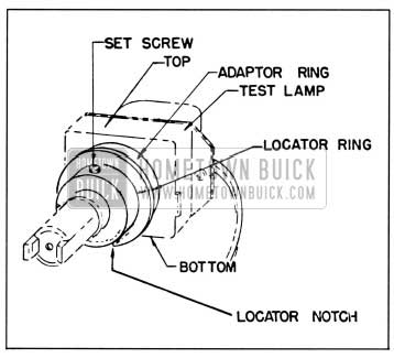
- Installing Test Lamp and Aiming Device. The test lamp is a very accurate source of light which is connected to a test instrument. The test instrument has a rheostat to adjust the test light intensity and a meter to accurately read that light intensity. To install the test lamp, remove the phototube cover and insert from the front. An adaptor ring fits into the lens slot with a locator notch down to accurately locate the test lamp. See figure 10-58.
1958 Buick Autronic-Eye Test Lamp
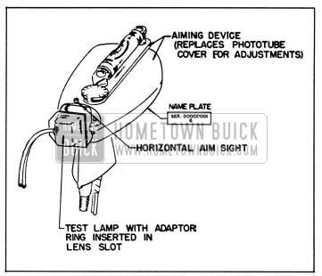
The aiming device consists of a special phototube cover with an adjustable level and two sights. The level is set with a dial to compensate for the varying calibration in the optics of each phototube. It is used to aim the phototube vertically. The two sights are used to aim the phototube horizontally. To install the aiming device, set it on the phototube base in place of the regular cover. Pull out slightly on the driver control knob so the aiming device will seat fully on the phototube base. Replace screws and tighten securely. See Figure 10-59.
1958 Buick Aiming Device and Test lamp Installed
NOTE: The aiming device contains a special plastic filter. This filter should be kept free of dust. If the filter is damaged, the aiming device must be returned to the tester manufacturer for repair. This filter doe s not replace the amber filter in the phototube which must be left in place.
- Horizontal Aim. The centerline of the phototube must be aimed parallel to the horizontal centerline of the car. Unsatisfactory operation on curved highways will result if horizontal aim is incorrect. The horizontal aim should be checked as follows:
- Locate car approximately 25 feet from a vertical wall or screen. See figure 10-60.
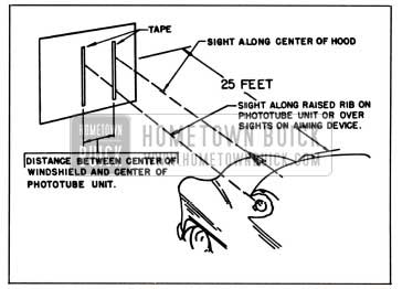
1958 Buick Horizontal Aiming
- Phototube vertical aiming should be done with car at normal road trim height; that is, car unloaded except for person in driver’s seat, trunk empty except for spare, gas tank at least half full, and with tires at correct pressure.
- Locate car on a level floor (level within 1/4″ fore and aft of car).
- Rock car sideways to equalize springs.
- Observe number stamped on name plate on bottom side of the phototube. See figure 10-61. Adjust aimer level dial until corresponding number is under pointer.
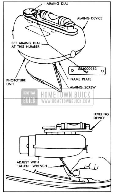
1958 Buick Vertical Aiming
- Make sure test lamp is properly installed (step 1 above) and that tester intensity rheostat is turned off full counterclockwise.
- Place driver sensitivity adjustment on phototube in detent position (knob pointer straight up).
- Start engine and set carburetor on high step of fast idle cam. This is necessary so that normal operating voltage will be present in the Autronic-Eye for all sensitivity tests and adjustments.
- Turn headlamps on and wait at least 5 minutes for amplifier to stabilize. Set foot switch in automatic position (upper beam indicator on).
- Turn zero corrector on face of meter until meter pointer is on zero set line.
- Insert tester connecter into cigar lighter receptacle (Sun Tester only).
- Turn “DIM-HOLD” switch to “DIM” position. NOTE: Sun Tester provides different selector switch positions for clear or tinted windshields; Kent-Moore T ester provides different meter scales for clear or tinted windshields. See Figure 10-62.
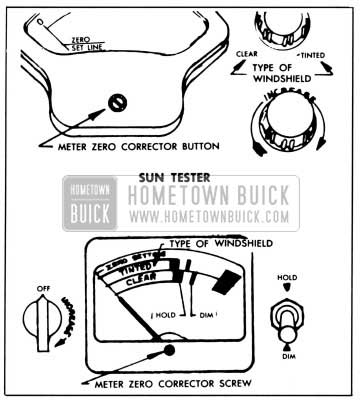
1958 Buick Autronic-Eye Testers
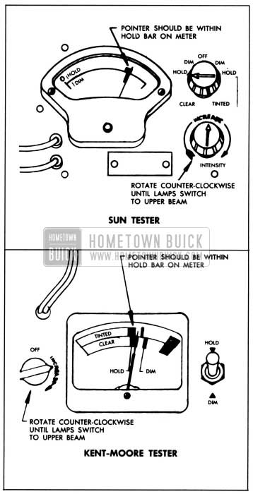
1958 Buick Testing Hold Sensitivity
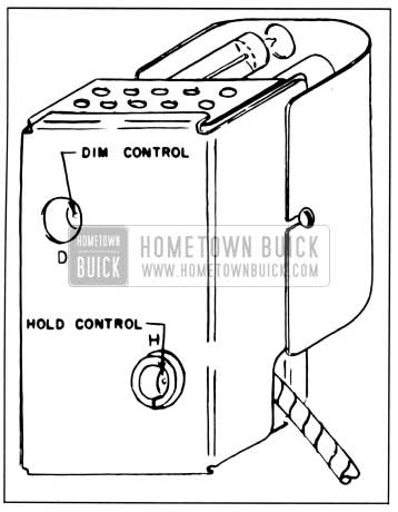
1958 Buick Autronic-Eye Sensitivity Controls
- Dim Sensitivity. This is a test to see how high the light intensity at the phototube will go before the headlamps “dim” from the upper beam to the lower beam. NOTE: Dim sensitivity should not be adjusted until after hold sensitivity is properly adjusted.
- Rotate tester intensity rheostat completely counterclockwise.
- Turn “DIM-HOLD” switch to “HOLD” position and then back to “DIM” position. Headlamps should be on upper beam.
- Turn tester intensity rheostat slowly clockwise (increasing intensity of test light) just to point where headlamps switch to lower beam. Meter pointer should read within the “DIM” adjustment line. See Figure 10-65. If adjustment is correct, proceed to step j. If not, adjust dim sensitivity as described in the following steps.
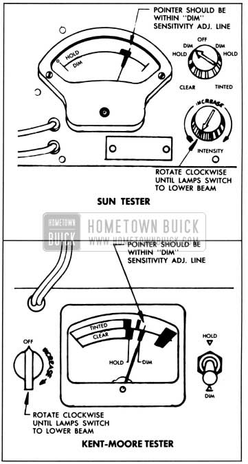
1958 Buick Testing Dim Sensitivity
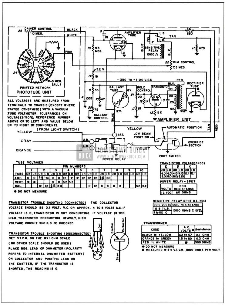
1958 Buick Autronic-Eye Schematic
10-50 1958 BUICK PARKING, TAIL, STOP, LICENSE AND BACK-UP LIGHTS
NOTE: See paragraph 10-5 for lamp bulb and fuse specifications.
1958 Buick Front Parking and Signal Lights
Each 1958 Buick front parking and signal lamp contains one 32-4 CP lamp bulb which provides a 4 CP parking light and a separate 32 CP direction signal light. The pins on lamp bulb and slots in socket are offset to prevent improper installation of bulb in socket. The 1958 Buick parking light is controlled by the lighting switch and the circuit is protected by the switch thermo circuit breaker. The 1958 Buick direction signal light is separately controlled by the signal switch and the circuit is protected by the “DIR. SIGNAL” fuse on the fuse block under the cowl.
1958 Buick Tail and Stop Lights
The upper section of each rear lamp assembly contains a 32-4 CP bulb which is used as a combination tail, stop, and direction signal light. The 1958 Buick tail lights are controlled by the 1958 Buick lighting switch and the circuit is protected by the switch thermo circuit breaker.
The 1958 Buick stop lights are controlled by a hydraulic switch mounted in the master cylinder. The switch is closed by hydraulic pressure when the brakes are applied. The direction signal switch is in the circuit, so the stop lights may be flashing or constant depending on the position of the switch. The 1958 Buick direction signal and stop light circuit is protected by the 10 ampere “DIR. SIGNAL” fuse mounted on the fuse block under the cowl.
Replacement of 1958 Buick Stop Light Switch
When replacing 1958 Buick stop light switch have new switch ready to install as soon as old switch is removed from master cylinder to keep brake fluid loss to a minimum. Always fill master cylinder reservoir after new switch is installed.
1958 Buick Rear License Light
A rear license lamp is mounted on each side of the 1958 Buick license plate in the under surface of the rear bumper rail to provide adequate lighting of rear license plate. Each lamp contains one 3 CP lamp bulb which operates in conjunction with the 1958 Buick tail lights, and the circuit is protected by the lighting switch circuit breaker. Each lamp socket is mounted in rubber to protect the lamp filament from shock and a bronze grounding washer completes the circuit when the mounting bolts are tightened.
The lamp bulb may be replaced by removing the lens from the license lamp housing.
1958 Buick Back-up Lamps and Switch
1958 Buick Back-up lamps are standard equipment on Series 70-700 cars and are optional on all other series. They are located in the lower section of each rear lamp assembly on Series 40-60 cars and in the outer corners of the rear bumper on Series 50-70-700. They contain 32 CP bulbs behind clear plastic lenses.
On Synchromesh cars, the back-up light switch is mounted on the steering column jacket. This switch is actuated by a pin on the switch itself which projects through a slot into the jacket. A short arm on the transmission control shaft actuates this switch pin while in the reverse position only. Slotted mounting screw holes permit movement of the switch up and down the steering column jacket for proper locating. See paragraph 10-31 (b) for adjusting procedure.
On Dynaflow cars, the back-up light switch is combined with the neutral safety switch. It is mounted on the steering column jacket under the instrument panel. The switch is actuated by a lever on the transmission control shaft which projects through a slot in the jacket. When the neutral safety portion of the switch is correctly timed, the back-up portion is properly timed automatically. Slotted mounting screw holes permit sidewise movement of the switch for proper timing. See paragraph 10-31 (a) for the adjusting procedure for the neutral safety and back-up light switch.
10-51 1958 BUICK INTERIOR LIGHTS AND CIGAR LIGHTERS
NOTE: See paragraph 10-5 for lamp bulb and fuse specifications.
1958 Buick Instrument Panel Lights and Switches
The 1958 Buick speedometer, gauges, light switch, heat-defroster or air conditioner control, and clock are illuminated by lamp bulbs mounted on forward side of instrument panel to provide indirect lighting. Illumination is also provided for the ignition lock and cigar lighter by means of a separate bulb and lens assembly which is held in place by spring clips. This bulb can be easily replaced by prying the bulb and lens assembly from the instrument panel.
The 1958 Buick instrument panel lights are controlled by the 1958 Buick lighting switch as described in paragraph 10-47 and the circuits are protected by the switch thermo circuit breaker.
1958 Buick Instrument Panel Compartment Light
The instrument panel compartment (glove box) is lighted by a lamp bulb mounted in a socket in the upper right corner of the glove box. The switch is mounted separately in the top right corner of the door opening. This spring-loaded switch makes contact when the compartment door is opened. As the door is closed it depresses the switch button to break contact and turn the light off. This circuit is protected by a 2 ampere fuse in the wiring connector behind the glove box.
1958 Buick Parking Brake Release Warning Signal
The parking brake release warning signal, when installed, will show a red warning signal light on the instrument panel whenever the ignition switch is turned on while the parking brake is applied. The signal lamp is controlled by a switch mounted in position to be operated by the parking brake lever. The circuit is protected by a 10 ampere “BRAKE & BACK-UP” fuse on the fuse block under cowl.
When brake lever is in fully released position, the signal switch plunger must be depressed 3/16”. Adjustment is made by loosening the mounting screws and shifting the switch as permitted by the slotted screw holes.
1958 Buick Direction Signal Indicator Lights
The direction signal indicator consists of a 2 CP bulb mounted at each end of the instrument cluster. A bulb may be replaced simply by pulling the socket from the back side of the cluster. Bulb location is the same in all series cars. See paragraph 10-54 for a complete description.
1958 Buick Dynaflow Control Dial Light
The Dynaflow control dial on all Dynaflow cars is illuminated by a lamp bulb mounted on the forward side of the instrument panel to provide indirect lighting. The light is controlled by the lighting switch in the same manner as all instrument panel lights. To replace the lamp bulb, remove the snap-in socket which is located directly under the instrument cluster.
1958 Buick Cigar Lighter
The Casco cigar lighter is heated by pressing the knob in until it latches; the knob will automatically unlatch and return to “off” position when heated to proper temperature. A replaceable thermal fuse which is screwed into the lighter base protects the lighter element against overheating if knob is manually held in for too long a period.
The lighter is equipped with an ash guard, to prevent ashes and loose tobacco from falling on the users clothing and to permit the lighter to be passed around without danger of burning the fingers.
Leave A Comment
You must be logged in to post a comment.