SECTION 3-E 1958 BUICK CARTER 2-BARREL CARBURETOR
3-15 DESCRIPTION AND OPERATION OF 1958 BUICK CARTER 2-BARREL CARBURETOR
General Description
The WGD Carter carburetor used on Series 40 engines is a 2-barrel down draft offset bowl type. See figure 3-17.
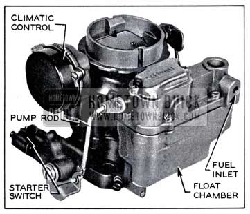
1958 Buick Carter WGD Carburetor Assembly
It contains a float system, low speed (idle) system, high speed system, power system, accelerating system, and climatic control (automatic choke). A carburetor starter switch, which is part of the cranking motor control circuit, is incorporated in the throttle body of 1958 Buick Carter 2-barrel Carburetor.
Air enters both barrels of 1958 Buick Carter 2-barrel Carburetor through the air horn which has one inlet and contains the choke valve. Fuel is supplied to both barrels from one float chamber. The float chamber is on the forward side of both barrels and contains a single float and lever assembly which operates a float needle or valve. The accelerating pump jet in each barrel is supplied with fuel from one pump located in the float chamber. The power systems of both barrels are controlled by one vacuum piston and link.
Except as noted above, each barrel forms a complete 1958 Buick Carter 2-barrel Carburetor system. Each barrel contains a low speed system with an adjustment screw, a high speed system with a metering rod, an accelerating pump discharge jet, a double venturi, and a throttle valve the throttle valves both barrels are mounted in line on one shaft. The dual construction combines the advantages of two carburetors in one compact unit. The dual carburetor and dual intake manifold provide more uniform distribution of fuel to all cylinders than would be possible with one single barrel carburetor.
The throttle body has a small vent in each barrel just above the throttle valve to permit the escape of any excess fuel or vapor which might accumulate due to percolation while idling or after shutting off an engine during very hot weather.
Operation of each system of the WGD Carter carburetor is described in the following sub-paragraphs. The climatic control is described in paragraph 3-16 which follows. The starter switch is described in paragraph 10-30.
Operation of Carter Float System
Fuel enters the 1958 Buick Carter 2-barrel Carburetor at the gasoline connection and flows through the needle seat into the float chamber. When the fuel reaches the prescribed level in float chamber, the float presses the needle against its seat to shut off the flow of fuel. Thereafter, the fuel is maintained at the prescribed level by opening and closing of needle as required. The float chamber is vented externally through a port in the air horn to allow fuel to be smoothly withdrawn through the various systems. See figure 3-18.
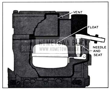
1958 Buick Float System
Operation of Carter Low Speed or Idle System
Fuel is delivered to the engine through the low speed system at closed throttle and light load speeds up to approximately 20 MPH. The low speed system also partially controls fuel supply for light load speeds up to approximately 30 MPH.
The operation of the low speed system in each barrel of the 1958 Buick Carter 2-barrel Carburetor is identical. Fuel flows from the float chamber through the metering rod jet into a passage which supplies both the low speed jet and the main nozzle. It then flows upward through the low speed jet which meters the fuel used by the low speed system. At the upper end of the low speed jet the fuel is combined with a stream of air coming in from the 1958 Buick Carter 2-barrel Carburetor throat through a by-pass. The combining of the air stream with the fuel tends to atomize or break up the gasoline into a vapor. See figure 3-19.
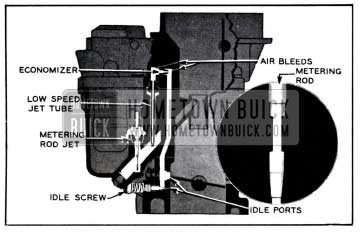
1958 Buick Low Speed System
The fuel-air mixture passes through a small drilled passage called the economizer and is combined with an additional air stream coming through the air bleed from the throat of the 1958 Buick Carter 2-barrel Carburetor. This additional air tends to break the fuel particles into a still finer vapor.
The fuel-air mixture that flows downward through the idle mixture passage and out through the two idle ports is still richer than an idle mixture needs to be, but when it mixes with the air coming in past the throttle valve, it forms a combustible mixture of the right proportions for idle speed. The idle adjustment screw permits regulation of the quantity of mixture supplied through the lower port.
The upper idle port is slotted vertically. As the throttle valve is opened it not only allows more air to come in past it but also uncovers more of the idle port, thereby allowing a greater quantity of the fuel-air mixture to enter the 1958 Buick Carter 2-barrel Carburetor throat from the idle mixture passage. See figure 3-19.
The closed position of the throttle valve is such that at idle speed of 8 to 10 MPH, it leaves enough of the slotted idle port in reserve to cover the range in speed between idle and the point where the high speed system begins to operate.
As the speed increases from approximately 20 MPH, the low speed system starts cutting out as the high speed system cuts in until the high speed system is carrying the entire load and the low speed system is doing nothing.
To combat engine stalling during warm-up on cool, humid days caused by “carburetor icing”, exhaust gas is circulated through a passage in the base of the 1958 Buick Carter 2-barrel Carburetor flange. The heat transferred helps prevent ice formation at the throttle valve edges and idle ports. See figure 3-20.
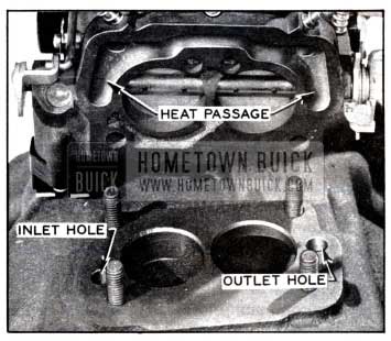
1958 Buick Exhaust Heat Passage
Operation of Carter High Speed System
The high speed system controls the flow of fuel during intermediate or part throttle operation starting at approximately 20 MPH.
The operation of the high speed system in each barrel of the 1958 Buick Carter 2-barrel Carburetor is identical. Air entering the barrel through the air horn passes through the double venturi system which increases the velocity of the air and creates a suction on the main nozzle. This causes fuel to flow from the float chamber through the metering rod jet into the main nozzle from which it is discharged into the air stream passing through the small venturi. The double venturi system tends to atomize or break up the fuel into a vapor and mix it with the air stream. See figure 3-21.
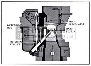
1958 Buick High Speed System
If any vapor bubbles are formed in the hot gasoline in the main nozzle passage, they rise in the low speed jet well and the vapor exhausts through the anti-percolator passage into the barrel. This avoids percolating difficulties which might occur if the vapor bubbles rose directly into the main nozzle.
The amount of fuel entering the high speed system is metered or controlled by the area of the opening between the metering rod jet and the end of the metering rod which extends into the jet. The lower end of the metering rod has steps with different diameters to provide different metering areas, depending upon the position of the metering rod in the jet. The metering rod is connected by a link, countershaft and connector rod to the throttle shaft so that it is raised when the throttle valve is opened and lowered when the throttle valve is closed.
At approximately 20 MPH the largest or economy step of the metering rod extends into the jet, thereby giving the smallest possible metering area. As the throttle valve is opened for higher speed or greater power, the metering rod is raised so that a tapered section and later the smallest or power step provides increased metering area between rod and jet. At top speed, the smallest or power step is in the jet.
Engines operated at part throttle on level road use a mixture of maximum leanness. The mixture for greatest power and acceleration is somewhat richer, and is furnished by the power and accelerating systems described below.
Operation of Carter Power System
For maximum power at any speed or for all operation above approximately 75 MPH, a richer mixture is required than that necessary for normal throttle opening. The richer mixture is supplied through the high speed systems of both barrels of 1958 Buick Carter 2-barrel Carburetor by means of the power system.
The power system consists of a vacuum piston located in a cylinder connected to manifold vacuum, a spring which tends to push the piston upward against manifold vacuum, and a vacumeter piston link attached to the piston and supporting the two metering rods. See figure 3-22.
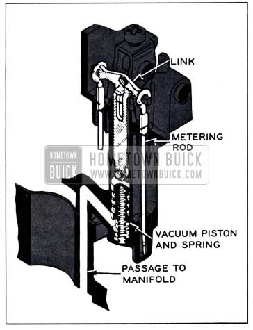
1958 Buick Power System
Under part throttle operation, manifold vacuum is sufficient to hold the piston and link down against the tension of the spring, so that the link is held against the tongue of the metering rod arm. The metering rods are then raised and lowered mechanically as the throttle valve is opened and closed. When the throttle valve is opened to a point where additional fuel is required for satisfactory operation, manifold vacuum decreases sufficiently so that the piston spring moves the piston, link and metering rods upward to the proper metering rod step position to give the required richer mixture, independently of throttle opening. As soon as the demand is passed, manifold vacuum moves the piston link down against the metering rod arm so that the metering rods are controlled mechanically again.
Operation of Carter Accelerating System
The accelerating system supplies the extra quantity of fuel which is needed momentarily for smooth and rapid acceleration when the throttle valve is suddenly opened.
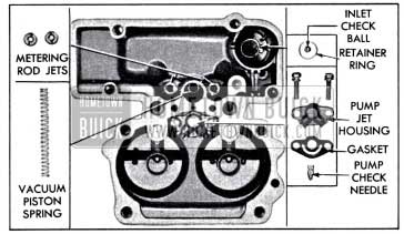
A pump plunger, operating in a cylinder cast into the float chamber, is mechanically operated from the throttle valve shaft by means of the throttle shaft arm, throttle connector rod, pump operating arm and countershaft assembly, pump arm and pump arm link. The pump circuit contains intake and discharge check valves and discharge passage leading to a pump jet in each barrel of 1958 Buick Carter 2-barrel Carburetor. See figure 3-23.
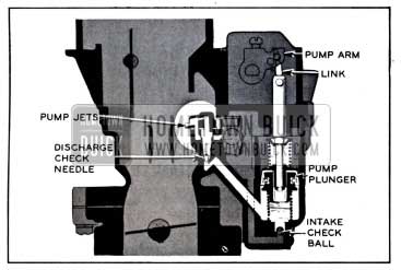
1958 Buick Accelerating System
When the throttle is closed, the pump plunger moves up and draws a supply of fuel from the float chamber past the intake ball into the pump cylinder. When the throttle is opened, the pump plunger on its downward stroke exerts pressure on the fuel which presses the intake ball against its seat, raises the check needle off its seat and discharges a metered quantity of fuel through the pump jets into each barrel of 1958 Buick Carter 2-barrel Carburetor. This occurs only momentarily during the accelerating period. The pump plunger spring provides a follow-up action so that the fuel discharge carries out over a brief period of time. See figure 3-23.
When the desired speed is reached and the throttle is held in fixed position, the pressure on the fuel in pump cylinder decreases sufficiently so that fuel ceases to discharge from the pump jets. With the throttle held in a fixed position the fuel flows only through the low speed or high speed systems as previously described.
At high speeds pump discharge is no longer necessary to insure smooth acceleration. When the throttle valves are opened a pre-determined amount, the pump plunger bottoms in the pump cylinder eliminating pump discharge due to pump plunger movement at high speeds.
During high speed operation, a vacuum exists at the pump jets. To prevent fuel from being drawn through the pump circuit, the passage to the pump jets is vented by a cross passage to the outside of the 1958 Buick Carter 2-barrel Carburetor body. This allows air instead of fuel to be drawn off the pump jets.
3-16 DESCRIPTION AND OPERATION OF CARTER CLIMATIC CONTROL (AUTOMATIC CHOKE)
General Description
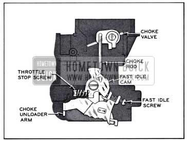
The climatic control consists of a choke valve mounted on a shaft in the 1958 Buick Carter 2-barrel Carburetor air horn, a bi-metal thermostatic coil and cover attached to a housing on the air horn, a vacuum actuated choke piston located in a cylinder in the housing on air horn, and a fast idle connector rod which connects a lever on the choke shaft to a fast idle cam mounted on 1958 Buick Carter 2-barrel Carburetor body flange. An upper heat pipe connects the choke housing to a lower heat pipe in the exhaust manifold.
The choke valve is mounted off-center on the choke shaft so that the force of air stream passing through the air horn tends to move the valve to the open position. A short lever riveted to the choke shaft is engaged by the free outer end of the thermostatic coil which, when cold, tends to close the choke valve. The choke piston, which is actuated by intake manifold vacuum, is connected by a link to the short lever on the choke shaft and tends to open the choke valve when the engine is running. See figure 3-24.
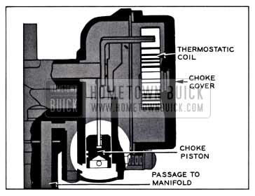
1958 Buick Climatic Control
The lower heat pipe in the exhaust manifold heats the air which is drawn through it and the upper heat pipe into the thermostatic coil housing. Two slots in the choke piston cylinder permit manifold vacuum to draw this heated air through the thermostatic coil housing and down into the manifold. A baffle plate separates the thermostatic spring from the housing on the air horn to insure circulation of heated air around the thermostatic coil.
The fast idle cam trip lever is connected by a rod to a choke lever on the outer end of choke shaft so that the fast idle cam is rotated as the choke valve closes. In closed throttle position when choke valve is not wide open, a fast idle adjustment screw on throttle shaft lever bears against the edge of the fast idle cam to give a greater throttle opening than that provided by the throttle stop screw. The edge of the cam is graduated in height from center to give increased throttle opening as choke valve moves toward closed position. When choke valve is in wide open position, the fast idle adjustment screw is opposite an opening in edge of cam so that throttle may close against the throttle stop screw.
Choke Operation-Cold Engine
When the engine becomes cold the thermostatic coil also becomes cold and increases its spring tension sufficiently to close the choke valve. It is prevented from closing the valve, however, because the fast idle adjustment screw holds the fast idle cam in the slow idle position; consequently, the choke valve is held partially open.
When the accelerator pedal is depressed to start the engine, the fast idle adjustment screw is lifted clear of the fast idle cam and the thermostatic coil then closes the choke valve. After the engine starts running, intake manifold vacuum causes the piston to partially open the choke valve against the spring tension of thermostatic coil, thereby admitting sufficient air to give a satisfactory running mixture.
When accelerator pedal is released after starting the engine, the fast idle adjustment screw comes to rest against a high point of fast idle cam which was rotated to the fast idle position by the closing of choke valve. This provides proper throttle opening to prevent stalling of the cold engine. See figure 3-25.
1958 Buick Climatic Control Linkage
If the throttle is partially opened while the running engine is cold, the vacuum piston and the increased force of air flow against the offset choke valve will open the valve against the spring tension of the thermostatic coil. These opposing forces balance the choke valve at a position which provides the required choke action without causing loading or an excessively rich mixture. At wide open throttle the vacuum piston does not help to open the choke valve.
Choke Operation-Warm-up Period
As the engine and exhaust manifold warm up, warm air is drawn through the heat pipes into the thermostat housing by manifold vacuum operating through the slots in choke piston cylinder. This warms the thermostatic coil, causing it to reduce its spring tension on choke valve in proportion to the increase in temperature. The choke piston moves the choke valve to a more open position within the range permitted by the fast idle cam trip lever, which can move independently of the fast idle cam which is held stationary at closed throttle by the fast idle adjustment screw.
When the throttle is opened and fast idle adjustment screw is lifted from the fast idle cam, the cam then rotates to bring a lower point into position for the fast idle adjustment screw. The engine will then run at a slower speed at closed throttle.
Choke Operation-Hot Engine
When the engine reaches normal operating temperature, the thermostatic coil is heated to the point where it no longer exerts any spring tension on the choke valve. The choke valve is in the wide open position and the fast idle cam is in the slow idle position so that the fast idle adjustment screw no longer contacts it at closed throttle. The throttle lever adjustment screw then governs throttle valve opening at closed throttle.
Choke Unloader Operation
If the engine becomes flooded for any reason, the choke valve can be partially opened by depressing accelerator pedal to the full extent of its travel. This causes a tongue or arm on the throttle lever to contact and rotate the fast idle cam, which forces the choke valve open. See figure 3-25.
Because the choke does partially open or “unload” when the accelerator pedal is fully depressed, the pedal should only be depressed when making a cold start just far enough to engage the starter switch. However, the 1958 Buick Carter 2-barrel Carburetor has a “start-aid” to help prevent unintentional choke unloading; it consists of a torsion spring which winds up when it contacts the unloader plate and provides resistance to further throttle opening when the choke is closed. Additional throttle opening causes a “snap-through” of the spring which notifies the driver that the choke is unloaded.
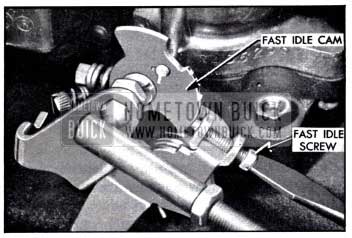
3-17 ADJUSTMENT OF FAST IDLE CAM, CHOKE UNLOADER, AND FAST IDLE SCREW
If the engine operates on fast idle too long after starting or else moves to slow idle too soon, or the choke unloader does not operate properly, check the following adjustments with the 1958 Buick Carter 2-barrel Carburetor either on the engine or on the bench.
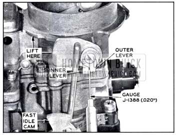
- Remove air cleaner. Open throttle to clear fast idle cam and close choke valve. With choke valve held fully closed and fast idle cam held against stop on casting by lifting on big end of inner lever, check clearance between lug on outer choke shaft lever and stop on inner choke shaft lever using Gauge J-1388 or a .020″ feeler gauge. See figure 3-26.
1958 Buick Checking Fast Idle Cam Clearance
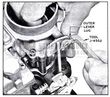
1958 Buick Adjusting Fast Idle Cam Clearance
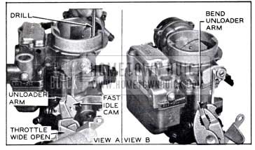
1958 Buick Choke Unloader Adjustment
1958 Buick Adjusting Fast Idle Speed on Engine
3-18 DISASSEMBLY, CLEANING, INSPECTION OF 1958 BUICK CARTER 2-BARREL CARBURETOR
Disassembly of 1958 Buick Carter 2-barrel Carburetor
- Place 1958 Buick Carter 2-barrel Carburetor on a suitable mounting fixture such as J-5923. Remove hair-pin from upper end of fast idle rod and remove rod. Remove choke shaft lever screw, outer lever, washer, and inner lever.
- Remove choke housing cover screws, retainers, choke cover assembly, gasket, and baffle.
- File off staked ends of choke valve screws, then remove screws and valve.
- Rotate shaft to disengage choke piston from cylinder. File burrs from choke shaft and remove shaft and lever assembly with piston attached. Remove three screws and remove choke housing from air horn. See figure 3-31.
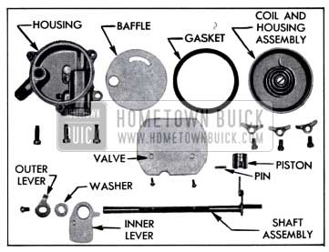
1958 Buick Climatic Control-Disassembled
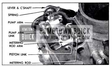
1958 Buick Metering Rod and Pump Operating Parts
1958 Buick Air Horn Parts
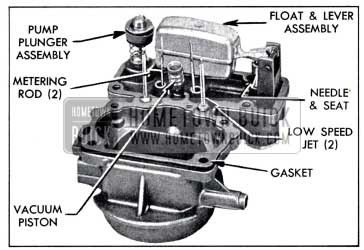
1958 Buick Main Body Parts
NOTE: lf starter switch screen is not visibly damaged or plugged, it need not be removed.
- Remove idle needles and springs. NOTE: The throttle body need not be disassembled further for normal cleaning and inspection.
Cleaning 1958 Buick Carter 2-barrel Carburetor Parts
Regardless of the number of new parts that are used in rebuilding a 1958 Buick Carter 2-barrel Carburetor, the job in the end will not be satisfactory unless all metal parts are thoroughly cleaned. Because of the nature of 1958 Buick Carter 2-barrel Carburetor parts, with numerous small passages subject to fouling with tenacious carbon and gum deposits, ordinary cleaning processes are entirely inadequate. The correct procedure is to use a cleaning bath in which metal parts can be immersed and “soaked” for sufficient time after disassembly to thoroughly clean all surfaces and passages.
Bendix Metalclene has been developed especially for cleaning carburetors, and is recommended for this purpose. Regardless of the cleaning material used, however, be sure to thoroughly rinse the parts in kerosene, distillate, or white gasoline to remove all gummy deposits that have been softened by the cleaner. Blow out all passages in castings with compressed air and blow off all parts so they are free of solvent.
Do not soak cork, plastic, or leather parts such as the starter switch terminal cap, switch guide block, choke thermostat cover1 and pump plunger in the cleaner. Wipe such parts with a clean cloth.
Remove all carbon from barrels of the body flange so that throttle valves may close properly. Be sure to clean all carbon out of idle ports.
Inspection of 1958 Buick Carter 2-barrel Carburetor Parts
After being thoroughly cleaned, all parts of the 1958 Buick Carter 2-barrel Carburetor should be carefully inspected for wear or damage as follows:
- Climatic Control. Check choke shaft for free action in air horn. If shaft is worn so that excessive play in bearings exists, replace the shaft assembly. If choke valve is bent or otherwise damaged it should be replaced.
Inspect thermostat cover for cracks and thermostat coil for distortion or other damage. If damaged, replace the cover and coil assembly.
Check the choke suction hole in choke housing which may be partially clogged with carbon.
Carefully note the condition of slots in the choke piston cylinder. If they are found to be carbonized, remove Welch plug in the bottom of the choke piston housing by piercing center with a small pointed instrument and prying outward. Care should be exercised so that damage will not result to the casting when removing the plug. Before installing new plug, carbon present in piston cylinder slots should be removed and the Welch plug seat should be carefully cleaned.
- Bowl Cover. Check for warped surfaces with a straight edge. Small nicks and burrs should be smoothed down to eliminate air or fuel leakage. Make sure that idle channels are clean and clear. If bowl strainer is damaged, or clogged so that it cannot be cleaned, it should be replaced.
- Float Needle and Seat. Because of the wear that normally occurs in these parts and the necessity of having a tight seating needle, it is advisable to replace these parts if the 1958 Buick Carter 2-barrel Carburetor has been used for considerable mileage. Even if mileage is low, replace these parts if needle is grooved or seat is damaged.
- Low Speed Jets. Test jets by blowing or sucking to make sure that metering holes are clear. Inspect small ends for damage which might deform the metering holes.
- Metering Rods, Jets, and Spring. Metering rods and jets are subject to wear in normal use. As the parts wear, the metering orifice becomes larger and a richer mixture results. If 1958 Buick Carter 2-barrel Carburetor has been used for considerable mileage, it is advisable to replace these parts since wear cannot readily be detected by inspection. If metering rod spring in vacumeter piston link is distorted or damaged it should be replaced since it performs an important function in keeping wear of metering rods and jets at a minimum.
- Vacumeter Piston. Inspect vacumeter piston and its cylinder for scoring or roughness. Piston and cylinder must be clean and smooth. If piston spring is distorted it should be replaced.
- Accelerating Pump Parts. Inspect countershaft assembly for wear of shaft and make sure throttle connector rod and holes in throttle shaft arm and pump operating lever for excessive wear. Inspect pump plunger leather washer for cracks, creases, turned edges, or other damage. Check holes in plunger shaft and pump arm, also pump arm link, for excessive wear.
Inspect pump intake ball for corrosion and the retainer for distortion.
Inspect pump check needle and replace it if tapered end is grooved or scored. Make sure that needle seat in main body is clean. Blow through each pump jet to make sure it is clean.
- Main Body. If passages in main body appear to be clogged with carbon and gum to such an extent that penetration of cleaning solution is doubtful, remove both nozzle passage rivet plugs using Rivet Extractor T 109-43. Do not attempt to remove nozzles or antipercolator plugs from main body under any circumstances.
After passages are thoroughly cleaned drive new rivet plugs securely into body openings, using care to avoid distortion of plugs or openings.
- Throttle Body Parts. Be sure that the idle discharge ports are clean of all carbon deposits and that the seats for idle adjustment screws are not damaged. If ends of adjustment screws are grooved or bent they should be replaced.
Make sure that the holes drilled through the rear wall of throttle body into each barrel are clear. These holes permit vapors to escape rather than rising into the air cleaner when engine is stopped.
Check wear of throttle shaft bearing and throttle shaft. There should not be more than about .005″ play between shaft and bearings, otherwise air leaks will interfere with performance. Make sure that throttle valves are not bent and do not have burrs or sharp edges.
- Carburetor Starter Switch. Clean and inspect parts of 1958 Buick Carter 2-barrel Carburetor starter switch as specified in paragraph 10-30.
3-19 ASSEMBLY AND ADJUSTMENT OF 1958 BUICK CARTER 2-BARREL CARBURETOR
During assembly of 1958 Buick Carter 2-barrel Carburetor, use all new gaskets and any additional new parts found to be necessary during inspection.
- Mount throttle body on fixture. Install idle needles and springs. Seat them lightly, then back out exactly 3/4 of a turn for a starting adjustment. Be careful not to force needle against its seat as this will score it and ruin it for use.
- Lubricate and install 1958 Buick Carter 2-barrel Carburetor starter switch parts as specified in paragraph 10-29. Check switch timing if there is any indication that switch is not functioning properly. If old starter switch screen was removed, install new screen.
- Place new gasket on throttle body and install main body.
- Place a new pump inlet check ball in inlet hole. Place ball retainer in small end of sleeve part of Installer T 109-122. Then insert retainer and tool in recess in bottom of pump cylinder and tap tool sharply to seat retainer. See figure 3-35.
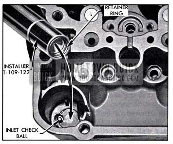
1958 Buick Installing Inlet Check Ball Retainer
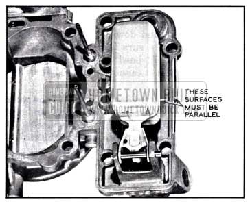
1958 Buick Checking Float Alignment
- Check to see that float is parallel with outer edge of air horn casting. Adjust if necessary by bending float arm.
- Place Gauge J 818-6 (14″) between air horn and center of float. If necessary, adjust float level by bending float arm until float just touches gauge. Float must not have excess clearance at hinge pin and must operate freely. See figure 3-37.
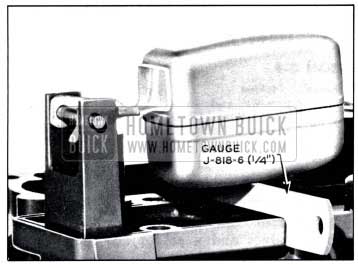
1958 Buick Checking Float Level
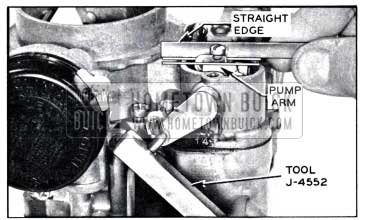
1958 Buick Checking and Adjusting Pump
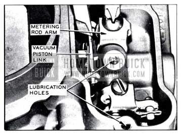
1958 Buick Adjusting Metering Rods
Leave A Comment
You must be logged in to post a comment.