SECTION 8-A 1958 BUICK MANUAL STEERING GEAR AND LINKAGE
8-1 1958 BUICK MANUAL STEERING GEAR SPECIFICATIONS
Tightening Specifications
Use a reliable torque wrench to tighten the parts listed to insure proper tightness without straining or distorting parts. These 1958 Buick manual steering specifications are for clean and lightly lubricated threads only; dry or dirty threads produce increased friction which prevents accurate measurement of tightness.
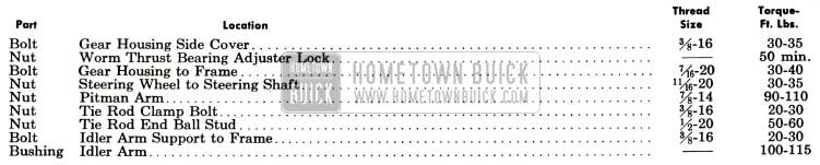
1958 Buick Steering Gear Tightening Specifications
1958 Buick Steering Gear Specifications
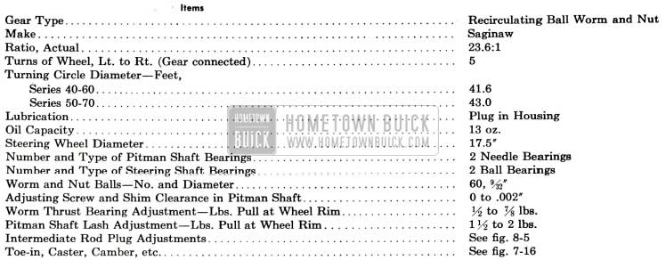
1958 Buick Steering Gear Specifications
8-2 DESCRIPTION OF 1958 BUICK MANUAL STEERING GEAR AND LINKAGE
1958 Buick Steering Gear Assembly
The 1958 Buick steering gear is the recirculating ball worm and nut type. The worm on lower end of the 1958 Buick steering shaft and the ball nut which is mounted on the worm have mating spiral grooves in which steel balls circulate to provide a low-friction drive between worm and nut. See figure 8-1.
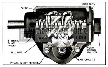
1958 Buick Steering Gear Worm and Nut, Showing Ball Circuits
Two sets of 30 balls are used, with each set operating independently of the other. The circuit through which each set of balls circulates includes the grooves in worm and ball nut and a ball return guide attached to outer surface of nut.
When the wheel and steering shaft turn to the left the ball nut is moved downward by the balls which roll between the worm and nut. As the balls reach the outer surface of nut they enter the return guides which direct them across and down into the ball nut, where they enter the circuit again. When a right turn is made, the ball nut moves upward and the balls circulate in the reverse direction. See figure 8-1.
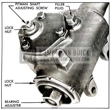
Teeth on the ball nut engage teeth on a sector forged integral with the pitman shaft. The teeth on the ball nut are made so that a “high point” or tighter fit exists between the ball nut and pitman shaft sector teeth when front wheels are in the straight-ahead position. The teeth of sector are slightly tapered so that a proper lash may be obtained by moving the pitman shaft endways by means of an adjusting screw which extends through the gear housing side cover. The head of adjusting screw and a selectively fitted shim fit snugly into a T-slot in the end of the pitman shaft, so that the screw also controls end play of shaft. The screw is locked by an external lock nut. See figure 8-2.
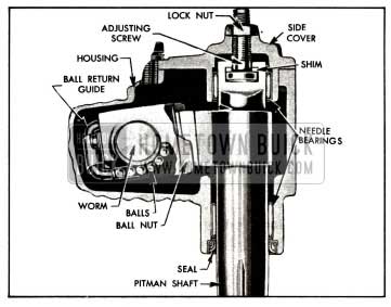
1958 Buick End Sectional View of Steering Gear
The 1958 Buick pitman shaft is carried by a needle bearing in the 1958 Buick steering gear housing and a needle bearing in housing side cover. A springloaded seal in housing prevents leakage of lubricant at outer end of the shaft. See figure 8-2.
The 1958 Buick steering worm shaft is carried by two ball thrust bearings which bear against seats on the ends of the shaft worm. The outer race of the upper thrust bearing is pressed into the gear housing.
The outer race of the lower thrust bearing is pressed into the bearing adjuster which screws into the housing and is locked by a nut. The 1958 Buick steering gear housing is attached to the frame by three bolts.
The upper steering shaft is a separate shaft supported in the 1958 Buick steering column jacket. Its upper end is supported by a ball bearing; its lower end by an adapter and ball bearing assembly. A nylon pin in the instrument panel support bracket fits in a slot in the mast jacket and locates it radially.
The upper steering shaft is connected to the steering worm shaft through a flexible coupling. This flexible coupling helps absorb minor shocks and vibrations, and gear rattle, and also allows slight variations in alignment between the 1958 Buick steering gear assembly and the steering column jacket assembly.
1958 Buick Steering Linkage
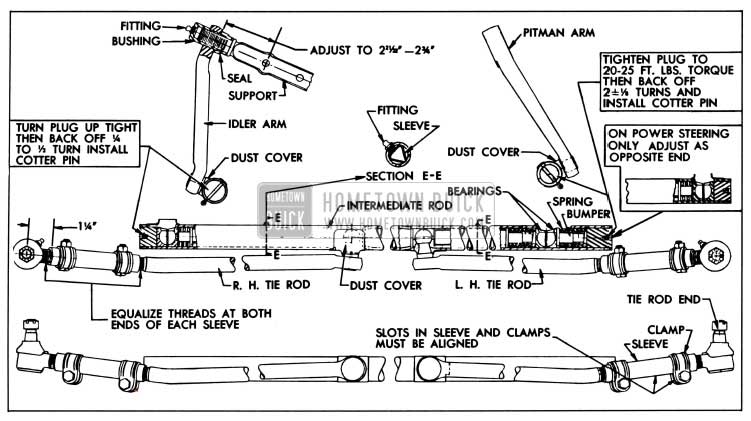
The Parallelogram type steering linkage is used to connect both front wheels to the 1958 Buick steering gear pitman arm. As shown in figure 8-5, the right and left tie rods are connected to a tubular intermediate rod. The left end of the intermediate rod is supported by the pitman arm and the right end is supported by an idler arm which pivots on a support attached to the frame. The pitman and idler arms are always parallel with each other and move through symmetrical arcs.
Each ball stud riveted to the tie rods, pitman and idler arms seats between pairs of ball socket type bearings contained in the intermediate rod. The bearings are held in firm contact with the ball studs through pressure applied by heavy coil springs located at the pitman and idler arm stud bearings. Steel spacers transmit this spring pressure to the tie rod ball stud bearings. See figure 8-5.
1958 Buick Steering Linkage
The linkages used for manual steering and power steering are the same except for ratio and that the anti-wheel kick springs at the pitman arm ball have been eliminated on the 1958 Buick power steering linkage, and the internal spline on the pitman arm is 1/8″ larger.
Flanged steel bumpers extending through the springs act as spring guides, permit a restricted movement of ball studs and bearings as the springs absorb road shock, and prevent the bearings from spreading and releasing the ball studs in the event of spring breakage. The spring tension and clearances at ends of bumpers are adjusted by the threaded end plugs. See figure 8-5.
The opening through which the ball studs enter the intermediate rod are protected by pressed steel dust covers to keep lubricant in and dirt and water out. Bearings and ball studs receive lubrication from inside the intermediate rod which is provided with two grease fittings.
The tie rod end, which connects each tie rod to a steering arm, is a spring-loaded ball stud and socket unit assembly. A rubber dust seal fits over the stud where it emerges from the socket, to provide protection against entrance of dirt and water. The tie rods are connected to the tie rod ends by internally threaded sleeves which provide for toe-in adjustment. The sleeves are slotted and provided with clamps at each end to lock them in place. See figure 8-5.
8-3 TROUBLE DIAGNOSIS – 1958 BUICK MANUAL STEERING GEAR AND LINKAGE
This paragraph covers improper steering actions which are most likely to be caused by the 1958 Buick steering gear assembly or tie rods. Improper steering actions which are most likely to be caused by chassis suspension members are covered in paragraph 7-6.
Excessive Play or Looseness in 1958 Buick Steering System
- Front wheel bearings incorrectly adjusted (par. 7-10).
- Worn upper ball joints (par. 7-11).
- Steering wheel loose on shaft, loose pitman arm, tie rods, or steering arms.
- Excessive pitman shaft to ball nut lash (par. 8-4).
Hard Steering-Excessive Effort Required at 1958 Buick Steering Wheel
- Low or uneven tire pressure (par. 1-1).
- Insufficient or improper lubricant in 1958 Buick steering gear or front suspension (par. 1-1).
- Excessive steering shaft coupling misalignment.
- Steering gear or tie rods adjusted too tight, or idler arm binding on support (par. 8-4).
- Front wheel alignment incorrect in one or more angles (p.a7-17).
- Frame bent or broken (par. 12-1).
Rattle or Chuckle in 1958 Buick Steering Gear
- Insufficient or improper lubricant in 1958 Buick steering gear (par. 1-1).
- Excessive back lash between half nut and pitman shaft sector in straight ahead position or worm thrust bearings adjusted too loose (par. 8-4). NOTE: On turns a slight rattle may occur, due to the increased lash between ball nut and sector as gear moves off the center or “high point” position. This is normal and lash must not be reduced to eliminate this slight rattle.
- Pitman arm loose on shaft, tie rod connections loose, or steering gear loose at mounting brackets.
- Loose fit at steering shaft upper bearing.
8-4 ADJUSTMENT OF 1958 BUICK MANUAL STEERING GEAR AND LINKAGE
IMPORTANT: Never attempt to adjust 1958 Buick steering gear while it is connected to intermediate rod. Steering gear must be free of all outside load in order to properly adjust worm thrust bearings and the lash between ball nut and pitman shaft teeth.
Adjustment of 1958 Buick Steering Gear In Car
- Disconnect intermediate rod from pitman arm by unscrewing end plug until bearings will release the ball stud. See figure 8-5. Check tightness of pitman arm nut with 18″ wrench.
- Turn 1958 Buick steering wheel gently in one direction until it stops, then turn it back one revolution. CAUTION: Never turn wheel hard against stopping point as damage to ball nut assembly may result.
- Check for lash between ball nut and pitman shaft by working the pitman arm. If a perceptible lash does not exist, loosen lock nut and turn pitman shaft adjusting screw counterclockwise, until lash can be felt when working pitman arm. This separates the worm thrust bearing load from the “high point” load caused by close meshing of ball nut and pitman shaft teeth.
- Turn 1958 Buick steering wheel slowly from one extreme position to the other. Wheel should turn freely and smoothly through entire range. Roughness indicates faulty worm thrust bearings or brinelled races. Hard pull or binding indicates excessive misalignment of steering shaft coupling, or an excessively tight adjustment of worm thrust bearings. Any misalignment must be corrected before steering gear can be properly adjusted.
NOTE: If 1958 Buick steering shaft coupling is out of alignment, check body mounting bolts which may have loosened and allowed body to shift.
- If binding exists readjust the 1958 Buick steering gear upper shaft assembly in its upper and lower mounting as described in paragraph 8-5.
- Loosen worm thrust bearing adjuster lock nut. Turn thrust bearing adjuster until a slight load is felt when turning 1958 Buick steering wheel near extreme positions, then tighten lock nut. See figure 8-3.
1958 Buick Steering Gear Adjustments
CAUTION: Do not back out adjuster far enough to permit thrust bearings to get out of line with ends of worm.
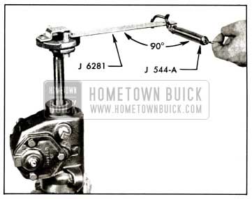
- After locking the bearing adjuster check the load on thrust bearings with 1958 Buick steering wheel turned to near one extreme position. Apply Scale J 544-A to a spoke at rim of wheel and exert a steady pull while keeping the scale at 90 degrees to spoke. The pull required to keep wheel turning slowly should be between 1/2 and 7/8 pounds. Readjust to obtain this bearing load if necessary.
- Turn steering wheel from one extreme position to the other while counting the turns, then turn wheel back one-half the total number of turns and have the lower spoke pointing straight down. This places 1958 Buick steering gear on the “high point” at which no lash should exist between ball nut and pitman shaft teeth.
- Tighten housing side cover bolts. Loosen lock nut and turn pitman shaft adjusting screw clockwise until lash between ball nut and pitman shaft teeth is just removed. Work pitman arm back and forth to feel for lash. After tightening adjusting screw lock nut, rotate steering wheel back and forth through the “high point” range and check for tight spots. Check pull at wheel with Scale J 544-A as described above.
- The pull required to keep wheel moving through “high point” should be between 1 1/2 and 2 pounds. Readjust if necessary to remove tight spots and obtain specified load at wheel rim. NOTE: If lash cannot be removed at “high point,” or if gear load varies greatly and feels rough, the gear assembly should be removed for inspection of internal parts.
Adjustment of 1958 Buick Steering Gear on Bench
- Place 1958 Buick manual steering gear in vise with worm shaft up. Then install Over-Center Adjuster J-6281 on flexible coupling. See figure 8-4.
1958 Buick Checking Thrust Bearing or Lash Adjustment with Scale
Adjustment of 1958 Buick Steering Linkage
The intermediate rod must be maintained in a level position to insure good steering action. This requires proper location of the idler arm on its support so that the idler arm ball stud will be level with the pitman arm ball stud. The support must be threaded into the idler arm bushing until the distance from the center of support lower bolt hole to the nearest face of idler arm is 2%” to 23¥3 2″, as shown in figure 8-5. After any adjustment of idler arm on its support the front wheels should be checked to insure proper toe-in.
IMPORTANT: If the idler arm support is dismounted from the frame for other work, such as removal of the lower crankcase, wire the support to the idler arm so that it cannot turn from its existing position and possibly change the toe-in of the front wheels.
Whenever the intermediate rod is being connected to the idler arm or pitman arm, be careful to properly seat the bearings around the ball stud and make sure that the pressed steel dust cover properly protects the opening around ball stud. On idler arm end of rod, turn the end plug up tight then back off 1/4 to 1/2 turn (1/2 turn preferred) and install cotter pin. On pitman arm end of rod, on 1958 Buick manual steering linkage, tighten end plug to 20-25 ft. lbs. torque then back off 1 7/8 to 2 1/8 turns and install cotter pin.
On the 1958 Buick power steering linkage, the pitman arm end plug adjustment is made in the same manner as idler arm end.
See paragraph 7-17 (subpar. e) for adjustment of tie rods to obtain proper toe-in of front wheels.
Road Test after Adjustment
Road test car for ease of 1958 Buick steering. If 1958 Buick steering gear was adjusted to specified load limits and hard steering exists, the front suspension members should be checked for lubrication and alignment and tire inflation pressures should be checked. When car is moving straight ahead, the lower spoke of steering wheel should be straight down, or not over 5/8″ to either side of straight down position. If lower spoke is too far to either side, check steering wheel for proper position on steering shaft (par. 8-5) and check tie rods for equal adjustment and toe-in (par. 7-17). It is important to have the steering gear in the no-lash range when car is moving straight forward.
8-5 1958 BUICK STEERING WHEEL REMOVAL, AND INSTALLATION
Removal of 1958 Buick Steering Wheel
- Disconnect wire at horn cable connector on 1958 Buick steering column to prevent horn from blowing.
- Remove horn button or operating ring (par. 10-52) then reinstall 1958 Buick steering wheel nut, leaving it backed off several turns.
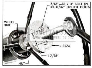
- Apply Puller J-3274 and pull wheel back to nut. See figure 8-6. NOTE: If wheel hub is very tight on shaft, apply a moderate strain with puller then tap end of puller screw to break hub loose from shaft without distorting wheel hub. Remove puller, nut, and 1958 Buick steering wheel.
1958 Buick Removing Steering Wheel with Puller J 3274
Installation of 1958 Buick Steering Wheel
- Install 1958 Buick steering wheel with location marks on shaft and hub of wheel in line.
NOTE: Location marks for proper installation of 1958 Buick steering wheel on steering shaft are provided to insure a vertical position of the steering wheel lower spoke when front wheels are in straight-ahead position. - With wheel properly located on shaft, install self-locking nut and tighten securely.
- Install horn button or operating ring (par. 10-52) and connect wire to horn cable connector on 1958 Buick steering column.
8-6 REMOVAL AND INSTALLATION OF 1958 BUICK MANUAL STEERING GEAR
Removal of 1958 Buick Steering Gear Assembly
- Mark upper and lower steering shaft flanges for correct assembly. Then disconnect the flexible coupling.
- Jack up car and remove the pitman shaft nut and lock washer, then remove the pitman arm.
- Remove the three steering gear to frame bolts at outside of left frame rail.
- Remove 1958 Buick steering gear from under car.
Installation of 1958 Buick Steering Gear Assembly
- Install the gear assembly by reversing the procedure for removal.
- Torque the pitman arm nut to 90-110 ft. lbs.
- Check toe-in after installation is completed.
8-7 DISASSEMBLY, INSPECTION, ASSEMBLY OF 1958 BUICK MANUAL STEERING GEAR
Disassembly of 1958 Buick Steering Gear
- Remove flexible coupling and mark coupling flange and steering worm shaft before disassembly.
- Support coupling flange and remove from worm shaft by driving pin out with punch. See figure 8-7.
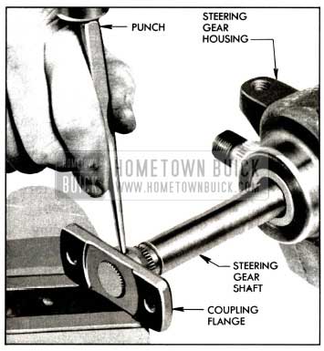
1958 Buick Removal of Coupling Flange
Cleaning and Inspection of 1958 Buick Steering Gear Parts
- Wash all parts in clean solvent and wipe dry with clean cloths.
- Inspect the worm, ball nut grooves and all balls for wear or scoring. Also inspect the thrust bearing rales on worm shaft for brinelling or scoring. Replace parts as necessary.
- Inspect thrust bearings and races for wear or scoring. Pry bearing retainer in adjuster out with screw driver if the race requires closer inspection. Replace as necessary using a tool of suitable diameter to drive new races in place.
- Inspect needle bearings in side cover and housing for wear or other damage. If replacement is necessary remove the needle bearings using bearing puller J-5822. See figure 8-8.
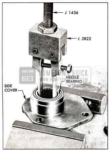
1958 Buick Removal of Needle Bearing
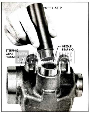
1958 Buick Installing Needle Bearing
Assembly of 1958 Buick Steering Gear
- Lubricate bearings and gears with specified steering gear lubricant.
- Assemble ball nut on worm, making sure that there are 30 balls in each circuit, making a total of 60 balls. Then install return guides and clamp. See figure 8-10.
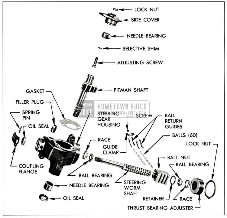
1958 Buick Steering Gear-Dissassembled
NOTE: When installing pitman shaft avoid damaging or turning the feather edge of the leather grease seal in gear housing.
- Install and tighten side cover bolts to 25 to 30 ft. lbs. Then install adjusting screw lock nut and flexible coupling.
- Fill 1958 Buick steering gear with specified lubricant and adjust gear on bench as outlined in Par. 8-4b.
Leave A Comment
You must be logged in to post a comment.