SECTION 10-I 1958 BUICK INSTRUMENTS AND CLOCK
10-55 1958 BUICK CHARGE INDICATOR, TEMPERATURE GAUGE, OIL PRESSURE GAUGE
CAUTION: Before disconnecting or connecting wires under the 1958 Buick instrument panel, or before attempting to remove any 1958 Buick instrument panel unit, always disconnect the battery ground strap to prevent any possibility of electrical arcs.
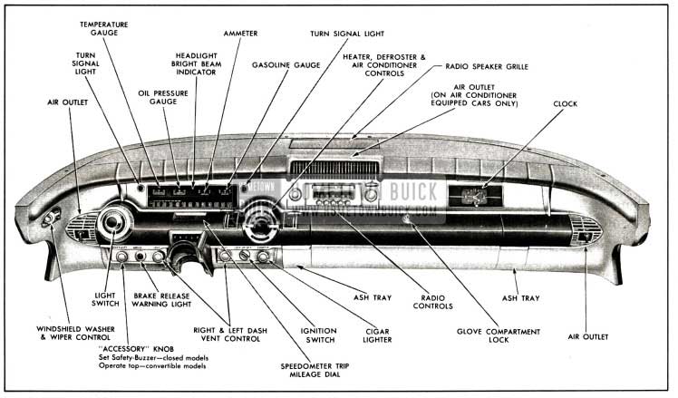
1958 Buick Instrument Panel and Instruments
1958 Buick Charge Indicator (Ammeter)
The AC charge indicator located in the 1958 Buick instrument cluster is similar to an ammeter; however, the scale is not graduated in amperes, therefore the indicator does not show the amount of current flowing. The current required to move the pointer against the stop is 10 amperes for both charge and discharge. The pointer is provided with a dampener, consisting of Silicone gel on the front pivot, to reduce pointer fluctuation when the voltage regulator is functioning.
The 1958 Buick charge indicator will indicate “charge” when the battery is being charged and “discharge” when the battery is being discharged. It gives an indication of the state of charge of the battery, since it shows a relatively high charging rate when the battery is low, and a low charging rate when the battery is near full charge. Immediately after cranking the engine, the charge indicator will be well over on the charge side for a short time, if lights and accessories are turned off. As the energy used in cranking is restored to the battery, the pointer will move back toward center but will stay slightly on the charge side. If the battery is low, however, the charge indicator will show a high charging rate for a considerable period of time.
The 1958 Buick charge indicator does not indicate charging rate of the generator since energy supplied by generator to electrical units other than the battery and horns does not pass through the indicator. At speeds above 30 MPH, with all lights and accessories turned on, the indicator should show a reading somewhere on the charge side, depending on the state of charge of the battery. Above 30 MPH, it should never show a discharge reading; if it does, the generator and regulator should be tested.
1958 Buick Temperature Gauge
The AC temperature gauge, located in the 1958 Buick instrument panel, is not an electrical instrument. The 1958 Buick heat indicator is a vapor pressure type which makes use of a sealed-in liquid, the expansion of which creates a pressure which moves the pointer on the gauge.
The 1958 Buick temperature gauge dial has a “C” to indicate a cold engine, an “N” with a bar to indicate normal temperature range, and an “H” to indicate that the engine is dangerously hot.
The 1958 Buick temperature gauge is a unit assembly consisting of a pressure gauge connected by a capillary tube to a vapor bulb. The vapor bulb is attached by a plug to the rear corner of the engine left cylinder head so that it extends into the cooling water. The heat of the water causes the sealed-in liquid in bulb to expand in proportion to temperature and exert pressure on the gauge in 1958 Buick instrument cluster.
The capillary tube is supported by a clip on the dash near its connection to cylinder head. A loop is formed – in tube between clip and cylinder head to absorb vibration, and allow for movement of engine on its mountings. When a new unit is installed this loop must be carefully formed and the tube must be supported in the clip. The tube must never be sharply bent or kinked, and must not be permitted to rub against the rocker arm cover.
1958 Buick Oil Pressure Gauge
The AC oil pressure gauge is not an electrical instrument. The gauge is the pressure expansion type which makes use of pressure developed by the oil pump acting directly on the mechanism of the gauge in the 1958 Buick instrument cluster. The gauge is connected by a small pipe to the main oil passage in the crankcase near the distributor. Connected at this point, it registers the full pressure of the oil pump.
The oil pressure gauge has an “L” to indicate low or no oil pressure, an “N” with a bar to indicate the pressure range for normal operation, and an “H” for high pressure.
10-56 1958 BUICK ELECTRIC CLOCK
The electric clock is mounted in the 1958 Buick instrument panel to right of radio. The clock wiring circuit is protected by the “clock” fuse on the fuse block under the cowl. The clock light is controlled by the rheostat in the lighting switch and is protected by the thermo circuit breaker. When burned out, this bulb can be replaced through a hole left in the glove box especially for that purpose.
Clock Time Reset and Automatic Regulation
The 1958 Buick electric clock incorporates a sweep second hand and an automatic regulator. A reset knob extends through the glass just under the clock dial. To reset the time, pull the knob out and turn in either direction as required. See figure 10-75.
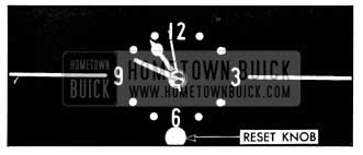
1958 Buick Electric Clock Reset Knob
There is no regulator knob because regulation is accomplished automatically by the action of resetting the time. If a clock is running fast, the action of turning the hands back to correct the time will automatically cause the clock to run slightly slower; if a clock is running slow, the action of turning the hands forward to correct the time will automatically cause the clock to run slightly faster (10 to 15 seconds per day).
A lock-out feature prevents the regulator mechanism from being moved more than once in 12 hours, regardless of the number of times the clock reset is operated.
Winding Clock When Connecting 1958 Buick Clock Wiring or Battery
The 1958 Buick electric clock requires special attention when reconnecting a battery that has been disconnected for any reason, a clock that has been disconnected, or when replacing a blown clock fuse. IT IS VERY IMPORTANT THAT THE INITIAL WIND BE FULLY MADE. To be certain of this, reconnect battery cables as follows:
- Make sure that all other 1958 Buick instruments and lights are off.
- Connect one cable (preferable positive) to battery.
- Before connecting the last cable to battery, press the terminal to its post on battery. Immediately afterward strike the terminal against battery post to see if there is a spark. If there is, allow the clock to run down until it stops ticking, and repeat as above until there is no spark. Then immediately make the permanent connection before the clock can again run down. The clock will run down in approximately 2 minutes.
- Reset clock after all connections are made.
NOTE: The above procedure should also be followed when reconnecting the clock after it has been disconnected, or if it has stopped because of a blown fuse. Be sure to disconnect battery cable before installing a new fuse.
1958 Buick Clock Service
The clock manufacturers have established Authorized Service Stations in many cities throughout the United States and Canada. These service stations are prepared to carry out terms of the manufacturer’s warranty and also to perform any repairs made necessary through use of clock.
When a 1958 Buick clock requires warranty service or repairs other than regulation, it should be removed by the Buick dealer and sent to the nearest authorized service station. The manufacturer’s warranty is void if repairs have been attempted outside of an authorized service station.
10-57 1958 BUICK GASOLINE GAUGE – DASH AND TANK UNITS
The AC gasoline gauge consists of two units; the dash unit located in the 1958 Buick instrument cluster, and the tank unit located in the gasoline tank. One terminal of the dash unit is connected to the ignition switch so that the unit registers only when the ignition switch is turned on. The other terminal of the dash unit is connected by a single wire to the tank unit, which is grounded on the tank to complete the circuit.
The dash unit pointer is moved by changing the magnetic pull of two coils in the unit. The magnetic pull is controlled by action of the tank unit which contains a variable rheostat, the value of which varies with movement of a float and arm. The tank unit is mounted in the tank so that the float rises and falls on the surface of the gasoline near the middle of the tank. The float is adjusted to provide approximately 1 gallon reserve when the dash unit pointer is at the dot next to the “E” position.
If the 1958 Buick gasoline gauge does not operate properly, the dash unit, tank unit wiring, and tank unit should be separately tested to determine which is at fault. The units and wiring may be tested with AC Gas Gauge Tester, Type No. 1, available through AC distributors.
If this tester is not available, a similar tester may be made from a new gasoline gauge tank unit. Attach a 5-foot piece of red colored insulated wire (#16) to binding post of tank unit, and attach a similar piece of black wire to the flange of unit. Attach spring clips to the free ends of both wires.
Test of Dash Unit
- With ignition switch turned off, disconnect the brown tank wire from dash unit terminal. Connect the red tester wire to this terminal and connect black tester wire to any convenient ground on car. Make sure that the other wire attached to dash unit has a tight connection.
- Turn ignition switch on, then move tester arm up and down against the stops. If dash unit is okay, the pointer will move freely from “Empty” to “Full” with movement of tester arm, indicating that the trouble is in wiring or tank unit. If pointer does not move, or only moves part way, the dash unit is faulty and should be replaced.
- Turn ignition switch off. If dash unit is okay, reconnect wire to terminal stud, being careful that the terminal of this wire does not come in contact with the other dash unit terminal, which would result in damage to tank unit rheostat.
Test of 1958 Buick Tank Unit Wiring
- With ignition switch turned off, disconnect tank unit wire (brown) at connector in luggage compartment. Connect the red tester wire to the wire running to dash unit and ground the black tester wire on car.
- Turn ignition switch on, then move tester arm up and down against stops while dash unit is being observed. If wiring is okay, dash unit pointer will move freely from “Empty” to “Full” with movement of tester arm, indicating that the trouble is in tank unit or the short wire leading to it.
- If, on the test, dash unit reads “Empty” at all times or the reading is noticeably lower than during the test of dash unit, look for a ground in the wiring between dash unit and bayonet connector. If dash unit reads above “Full” at all times or if it reads higher at “Empty” and “Full” than readings obtained on dash unit test, look for points of high resistance such as dirty connections, broken wire strands, or open circuit.
Test of 1958 Buick Tank Unit
- If tests given above indicate that the trouble is in the tank unit, remove the 1958 Buick gasoline tank so that the tank unit may be cleaned and tested.
- Before removing unit from gasoline tank clean away all dirt that has collected around the tank unit, and note whether the insulation was in proper position over the terminal and wire. Rood dirt, particularly calcium chloride, may have caused an electrical leak that threw the tank unit out of calibration.
- After thorough cleaning and removal of tank unit, connect it to ground and to wire leading to dah unit, and test in the same manner as when using tester. If tank unit tests okay it should be reinstalled in tank, otherwise it should be replaced with a new unit. When installing tank unit make certain that insulation is folded over the terminal and snapped over wire.
10-58 1958 BUICK SPEEDOMETER
Speedometer Heads
The AC speedometer head has a magnetic speed indicator and a gear driven odometer. It is driven by a flexible cable connected to a worm gear in the transmission rear bearing retainer. See paragraph 4-7 for gear ratios.
The 1958 Buick speedometer head has a long drum painted half red and half black on the diagonal so that as the drum revolves a red line moves horizontally across the dial face. See figure 10-76.
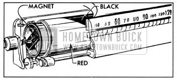
1958 Buick Drum Type Speedometer
All 1958 Buick speedometer heads are provided with a trip odometer and reset knob. Pushing the reset knob up and turning clockwise gives a quick reset; turning knob counterclockwise resets 1/10 mile at a time.
Checking Noisy 1958 Buick Speedometer
- Jack up rear wheels in safe manner and close car windows to exclude outside noises.
- With transmission in direct drive, run slowly from 0 to 50 MPH and back to 0, noting speed range where noise appears.
- Apply brakes and shift transmission to neutral or parking position, then run engine through same speed range as before.
- If the noise continued in step 3, something other than the speedometer installation is at fault. If noise disappeared, inspect and lubricate speedometer cable (subpar. c). If this does not correct the noise, have speedometer head checked by an authorized AC Speedometer service station.
Inspection and Lubrication of 1958 Buick Speedometer Cable
If the 1958 Buick speedometer installation appears to be noisy or the speed indicator wavers, inspect the cable casing for damage, sharp bends, or for being out of the supporting clips. If casing is in good condition and properly installed, remove cable for inspection and lubrication.
- Disconnect 1958 Buick speedometer cable casing at the speedometer head, then pull cable out of upper end of casing.
- Inspect cable for worn spots or breaks. Check cable for kinks by holding one end vertically in each hand and turning cable slowly; if cable is kinked the loop will “flop.” Replace a kinked cable.
- Coat the lower two thirds of the cable with AC type ST-640 speedometer cable lubricant. If this is not available, No. 110 Lubriplate may be used. As cable is inserted into casing from upper end the lubricant will spread over its entire length.
- When cable is connected to speedometer head make sure that the felt dampener washer is in place over the cable collar and that the cable tip seats properly in the head socket.
Trouble-Shooting 1958 Buick Speedometer Safety-Minder
The 1958 Buick Safety-Minder is standard equipment on Series 70-700 and is a factory installed option on all other series. This feature consists of a buzzer which may be adjusted by the driver to sound at any speed between 20 and 110 MPH by turning a knob on the lower instrument panel. The speed at which the Safety-Minder is set is indicated by a dial in the lower left corner of the speedometer face.
The 1958 Buick Safety-Minder electrical circuit starts at a 1 ampere fuse marked “ACC”, located on the fuse block. See figure 10-77.
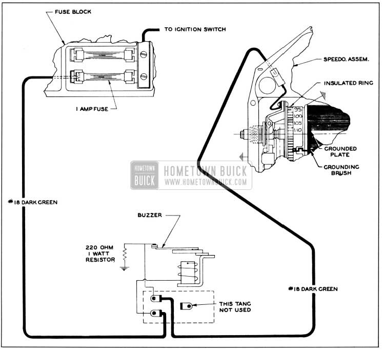
1958 Buick Safety-Minder Circuit Diagram
This circuit is “hot” whenever the ignition switch is turned on. From the fuse, a dark green wire carries the current to a buzzer mounted on the left ventilator air deflector. After passing through the buzzer contacts, a very small amount of current goes through a resistor to ground and the rest of the current passes through a second dark green wire to a connector on the speedometer case.
In the 1958 Buick speedometer, current is conducted to an insulated ring which has a dial reading from 20 to 110. A grounding brush projects from this insulated ring in such a position that a grounded plate on the speedometer cylinder will contact it as the cylinder rotates, thereby grounding the circuit and causing the buzzer to operate.
The insulated ring with its dial and grounding brush can be rotated by turning the reset knob while observing the dial through a small window in the lower left corner of the speedometer. The car will then have to be moving at the rate of speed indicated on this dial before the speedometer cylinder will rotate far enough for its grounded plate to contact the brush.
- Buzzer Will Not Operate or Operates Intermittently
- Disconnect 1958 Buick buzzer circuit at speedometer. To get at this connector, slip fuse block down and reach up with left hand between fuse block brackets and forward of heater duct to upper left corner of speedometer. Feel location of connector to make replacement easier. Then remove connector by sliding it sideways.
- To check complete buzzer circuit up to speedometer, ground this connector with ignition switch turned on. (For a convenient means of grounding, push a paper clip into connector). If buzzer now operates, circuit is OK and trouble must be in speedometer. Before removing speedometer, however, double check this by reinstalling connector on speedometer. Then jack up rear wheels and run speedometer up through speed set on Safety Minder.
- If buzzer did not operate when speedometer connector was grounded (in step 2), trouble must be in buzzer circuit. Check fuse at “ACC” on fuse block and replace if necessary with a one ampere fuse.
- Check buzzer circuit wiring connectors at fuse block, buzzer, and speedometer. See figure 10-77.
- Next eliminate buzzer as source of trouble by unplugging connector at buzzer which is mounted on left ventilator air deflector. Then plug a known good buzzer onto the connector. There is no need to ground buzzer – just let it hang from connector.
- Buzzer Operates Continuously
- Check green wire from buzzer to speedometer for ground.
- Disconnect wire at speedometer as described in step 1 above. If buzzer stops, circuit is grounded inside speedometer and speedometer must be removed for repair. If buzzer still operates, however, buzzer unit is defective and must be replaced.
- Reset Shaft Binds
- Check knob for interference with 1958 Buick instrument panel. Relieve if necessary.
- Check routing of reset shaft. Must route “over” light switch instead of between light switch and speedometer.
- Check end play. Shaft should be free.
- Determine if cable is bent at speedometer mounting bushing. If reset shaft continues to bind after making the above checks, then remove speedometer assembly.
- Speedometer Sticks
- Check to see that buzzer is latest type having a resistor. This can be identified by a pig-tail welded to the mounting base. Replace buzzer if it is not of the latest type.
- If above does not correct, send speedometer assembly to the nearest UMS Service Station for repairs.
Leave A Comment
You must be logged in to post a comment.