SECTION 7-D 1958 BUICK AIR-POISE SUSPENSION
7-18 1958 BUICK AIR-POISE SPECIFICATIONS
Tightening Specifications
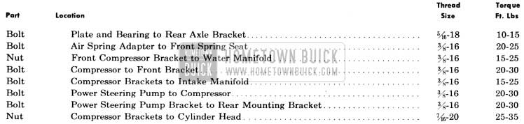
1958 Buick Air Poise Suspension Tightening Specifications
Test and Assembly Specifications General
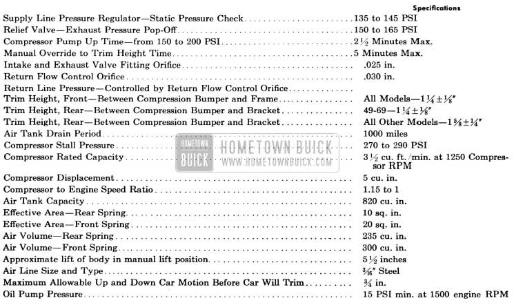
1958 Buick Air Poise Suspension – Test and Assembly Specification
Compressor Production Limits & Fits
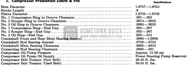
1958 Buick Air Poise Suspension – Compressor Production Limits and Fits
Height Control Valve Specifications
Neutral period of valve (air exhaust and air intake valves closed) … 2 1/2” (.054)
7-19 DESCRIPTION AND OPERATION OF 1958 BUICK AIR-POISE SUSPENSION
General Description
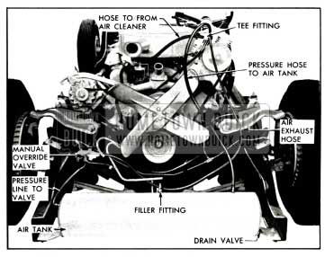
1958 Buick Air-Poise Suspension, available as optional equipment on all series equipped with power steering, utilizes air springs at all four wheels to replace the conventional coil springs of previous years. See Figure 7-19.
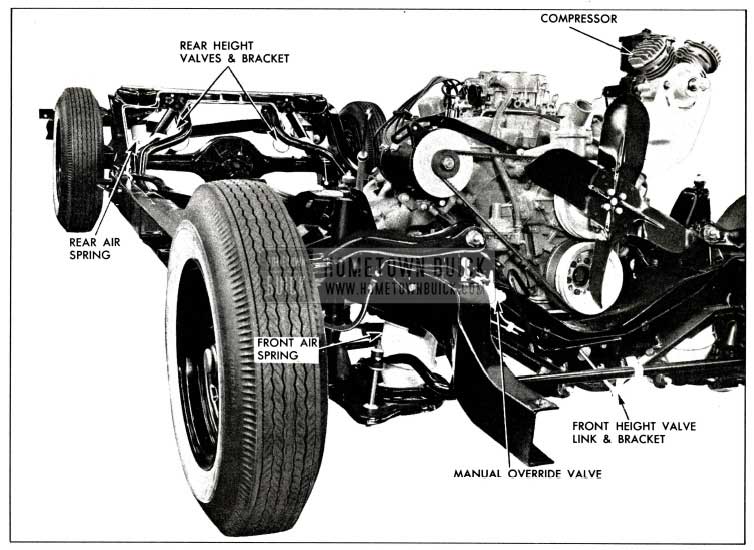
1958 Buick Air-Poise Chassis
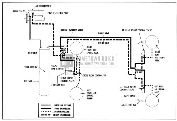
1958 Buick Schematic of Air-Poise Suspension
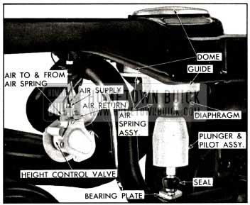
The engine drives a compressor which supplies air at approximately 280 psi pressure to an air storage tank. The tank acts as a reservoir and supplies air as needed to a manual override valve which reduces and regulates this 280 psi to a constant lower pressure. This is the air pressure which then is passed to three height control valves; one at each rear air spring and another that controls both front air springs. From the height control valves, air goes directly to the air springs.
Air in the springs will exhaust with removal of load and for this purpose separate return lines are provided to return air from the air springs, through the height control valves, back to the manual override valve and to a tee fitting at the compressor where the air may either be used by the compressor or may exhaust out the air cleaner.
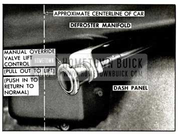
All of the described operation is done automatically, the same as any conventional coil sprung car. However, a control is located at the dash which must be manually operated to raise the car when the need for changing a tire and wheel arises. See Figure 7-21.
1958 Buick Manual Lift Control
The bumper jack can then be used, as with coil spring suspension, to raise the car and then remove the wheel. This feature locks out the automatic control of the height control valves.
Compressor
A two-cylinder die-cast aluminum compressor with a 1 7/8 inch bore, a stroke of .9 inches front of the power steering pump and is bolted to it. See Figure 7-22.
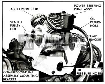
1958 Buick Air Compressor-Power Steering Pump Assembly
A single belt drives the compressor at a speed ratio (compressor to engine) of 1.15 to 1. A check valve at the air outlet fitting prevents leakage of air from the air tank through the compressor when the engine is not running.
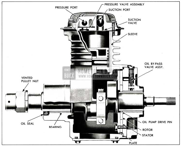
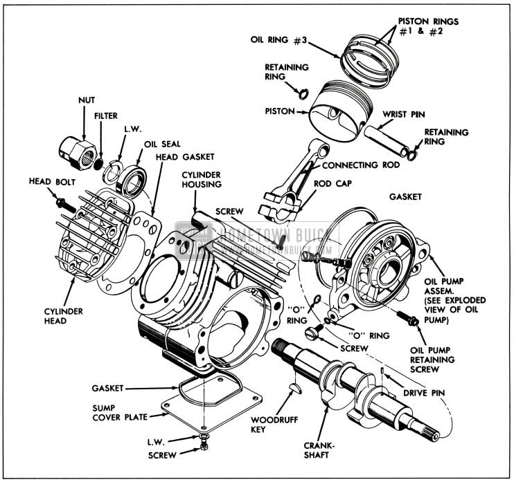
The front crankshaft babbit bearing and a double lip oil seal, are pressed into the front of the block. Steel cylinder sleeves are cast in and cannot be replaced. At the top of the block are two holes for each cylinder; one air inlet and a smaller exhaust which lead to exterior holes tapped for fittings.
1958 Buick Air Compressor Cutaway
The heads also are die-cast aluminum and ribbed for cooling. They are interchangeable, and a displacement of 5 cubic inches is used. It has a stall pressure, or maximum built-up pressure, of approximately 280 psi; is located in side for side. A composition gasket is used between the heads and cylinder housing. One exhaust valve and one intake valve are located on the under side of the head. The exhaust valve is attached to an aluminum valve plate and the assembly is then a shrink fit in a recess in the head. It is not replaceable. The intake valve is positioned over two dowels which align with two holes in the cylinder block and is located on the block side of the head. It can be replaced if necessary.
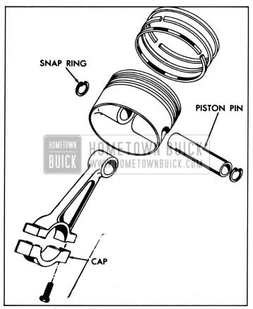
A three-ring, die-cast aluminum piston with a full floating piston pin is used. Piston pins are held in position by snap rings at either end of the pin opening in the piston.
The connecting rods are cast aluminum. The rods and rod caps are tin plated at the bearing area.
A cast crankshaft is used which is supported by the crankshaft bearing in the front of the housing and another babbitt bearing in a rear bearing plate. The driving pulley drives the crankshaft through a woodruff key and is held on by a special nut. The rear end of the crankshaft is splined and drives the power steering pump rotor. Pressed into the crankshaft at the rear main bearing journal is a small pin which drives the compressor oil pump. It engages with a slot in the pump rotor. The shaft is drilled from the rear main bearing journal into the rod bearing journal and serves as an oil force feed to the connecting rod bearings. An air bleed hole is drilled through the center of the crankshaft, extending from the front of the shaft to the front counterweight. The pulley retaining nut on the crankshaft is vented.
The vane type pump, having only two vanes, is mounted at the rear of the compressor and furnishes oil under a pressure of 20 psi to both main bearings and rod bearings. Oil is picked up from just above the bottom of the power steering reservoir, enters a hole in the rear bearing plate and is put under pressure by using only one half of the two section pump. Oil is passed into a passage which houses a by-pass valve. The valve limits the pressure and by-passes excess oil. Oil at the regulated pressure then goes to the rear main bearings and also to the drilling in the bearing journal and finally to the connecting rod bearings. One additional drilling, in the rear bearing plate casting, routes oil at regulated pressure to a drilling in the rear of the cylinder block, through the block and up to the front crankshaft bearing where it enters through a hole in the bearing. All oil drains into a sump in the bottom of the cylinder block where it is picked up and routed through a passage leading to the pump. The scavenger half of the pump returns the oil to the power steering reservoir, with the oil entering through one of the two stand pipes.
Air Tank
A cylindrical air tank, having a capacity of 820 cubic inches, is positioned between the frame side rails just rearward of the front bumper face plate. It is pressurized at compressor stall pressure of 280 psi and serves as an air reservoir and water trap. Two brackets are welded to the bottom at each end of the tank and the brackets are bolted to the frame. See Figure 7-24.
1958 Buick Air Tank Assembly
There are two fittings welded to the top of the tank. The one on the left is for air under pressure coming from the compressor; the other is a Schrader type valve, normally used for manually filling the tank and diagnosis. Midway on the right end, another fitting serves as the outlet. At the bottom of the left end is a valve which should be opened periodically (every 1000 miles) for draining of any water and oil which may have come through the compressor. The inside of the air tank is coated with zinc chromate for protection against rust.
Manual Override Valve
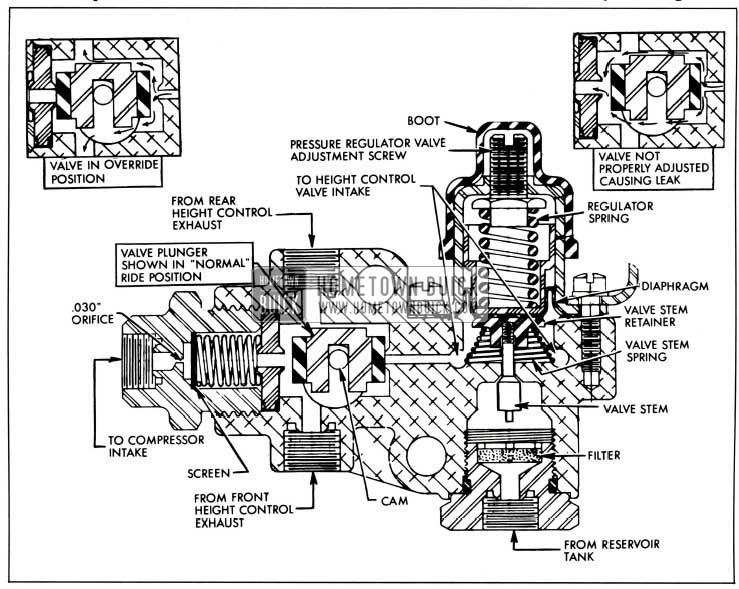
The manual override valve assembly is bolted through a bracket to the frame front spring cross member at the right side. One of its functions is serving as a junction block for most of the air lines. It also reduces and regulates the high pressure coming from the tank to a static supply pressure of approximately 140 psi. Incorporated in the exhaust side of the valve is the return flow control orifice which restricts flow of air from the return lines to atmosphere.
For a close-up external picture see Figure 7-25.
1958 Buick Manual Air Pose Override Valve
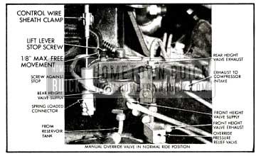
An important function of the override valve is to allow raising the car to its full rebound position when the need for changing a wheel or tire arises. This is done by raising a lever on the valve through a Bowden control wire which extends into the driver compartment through the right side of the dash.
When the lever is in its normal down position, the air routing is from the override valve, through air supply lines to the two height control valves in the rear and the one height control valve in the front. See Figure 7-26.
1958 Buick Manual Override Valve-Sectional View
The pressure within these lines is maintained at approximately 140 psi. When the lever on the override valve is raised, the exhaust line leading to the air cleaner is shut off, and the air return lines are opened to the same pressure as in the pressure lines. See Figure 7-26. This pressure feeds to the height control valves and the valves allow the car to be raised approximately 5 1/2 inches. When the lever is returned to its normal position, the air return lines are shut off from the supply pressure and the exhaust passage leading to the return flow control orifice is opened, allowing the excess air to slowly bleed out from the return lines through this orifice until pressure lowers to atmospheric pressure.
When it becomes necessary to change a tire or wheel, or if the car must be jacked up or raised on a free-wheel hoist for any reason, the override valve must be actuated so that the car will be raised to a full rebound position. The car may then be raised in the conventional manner.
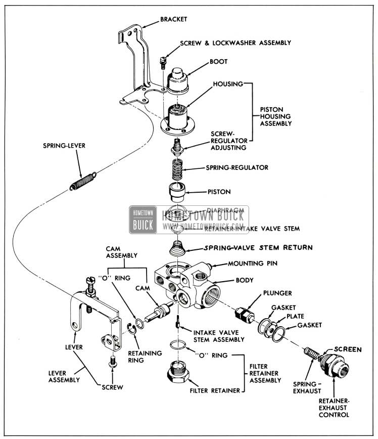
1958 Buick Height Control Valves
Three height control valves are used; one for each rear wheel and one for both front wheels. All the valves are identical in construction and operation with the exception of the lever arms which are longer on the rear valves. The valves work together to keep the trim height of the car constant regardless of weight load or level of the ground. They do this by controlling the air flow into or out of the air springs.
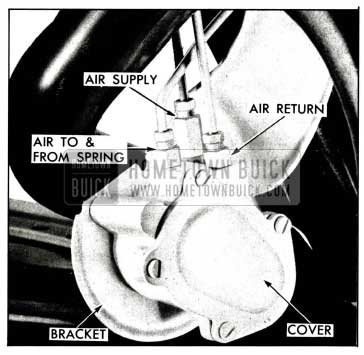
1958 Buick Rear Height Control Valve
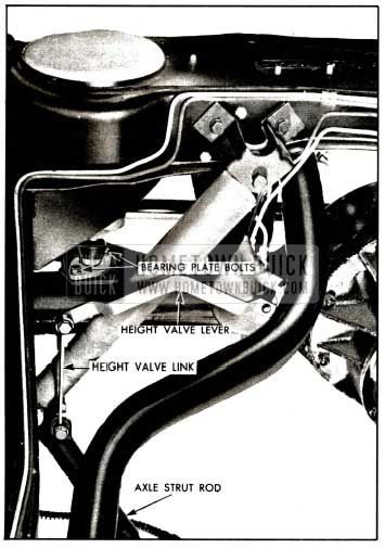
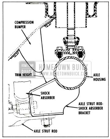
Each 1958 Buick rear height control valve is mounted to a bracket by two cap screws and the bracket is bolted to the front side of the frame rear spring cross member. The two holes in the bracket are elongated to allow positioning of the valves when trim height corrections are necessary. The valve operating arms are connected to links which in turn are bolted to the rear axle strut rods. See Figure 7-28.
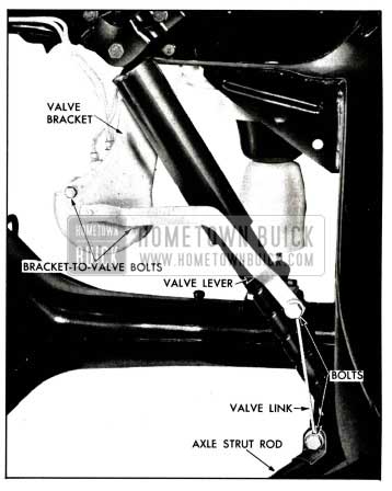
1958 Buick Rear Height Control Valve Assembly
Vertical motion of either rear wheel will move the link and therefore the arm. The direction of vertical motion will determine whether the valves will allow the air springs to take in more air or exhaust some of the existing air. Rear height control valve links on 49-69 models are different from other models, the difference being in length.
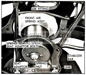
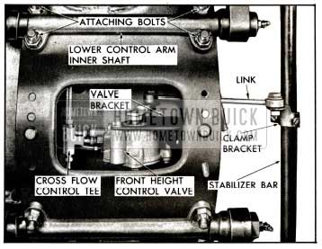
The 1958 Buick front height control valve is located on a bracket inside the front spring cross member and in line with the center line of the car. See Figure 7-29.
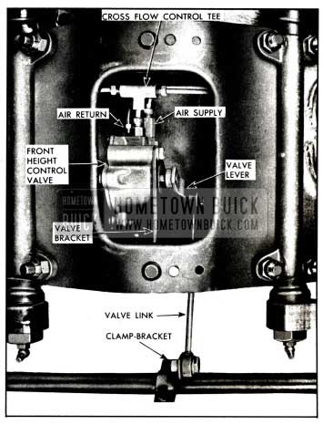
1958 Buick Front Height Control Valve Assembly
One end of a link is connected to the valve arm with the other end connected to a lever. The lever is clamped to the stabilizer bar and allows for positioning of the front height control valve when trim height corrections are needed at the front. Whenever either front wheel or both move up or down, the stabilizer bar will twist and transfer this motion to the valve link and arm. The valve will then allow the air spring to either exhaust or take in additional air, depending on the direction the wheel moves.
A feature is built into all height control valves to prevent opening and closing of the valves each time a small bump or series of small bumps are encountered. The wheels can be either raised or lowered approximately 3/8″ from their normal trim or “neutral” position before the valves will open or close. This is due to a “dwell” period built into the valve.
To reduce sensitivity, an orifice is built into all intake and exhaust valve fittings. Since the compression-rebound cycle of the air spring is of such short duration, these restrictions allow very little air movement during the short time the valves are open.
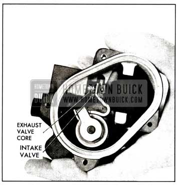
1958 Buick Height Control Valve-Cover Removed
When a car is at curb weight, the trim height will be correct. As soon as weight is added, such as the addition of passengers, the car lowers and the height control valve arm moves up. See Figure 7-31.
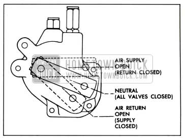
1958 Buick Height Valve Arm Action
A Schrader type valve in the air supply (intake) fitting is mechanically opened. A second Schrader valve in the fitting is opened by supply line pressure. With both intake valves open and the exhaust closed, air is allowed to flow into the air springs, until the car is raised to its normal trim height and all valves are closed.
When weight is removed and the car raises, the valve arms move down and open the Schrader type exhaust valves, thereby allowing excess air to pass out of the air springs until the car lowers to its normal trim height and the valves close.
Trim height settings must be as close as possible to the specified limits. By deviating outside the limits, the riding qualities will be materially affected.
Cross Flow Control Tee
To materially improve cornering stability a cross flow tee is provided for the front air springs.
1958 Buick Front Air Spring Mounting
It is inserted in the air supply line between the air springs and the height control valve and attached to the height control valve. See Figure 7-29. Inside the tee are two check balls, one for each spring, which are forced off their seats when air flows toward the air springs, but are forced against the seats when air flows from the springs. The seats, however, have metered orifices which allow a restricted flow of air. Therefore, when cornering, air from the high pressured spring cannot flow freely to the spring with lesser pressure.
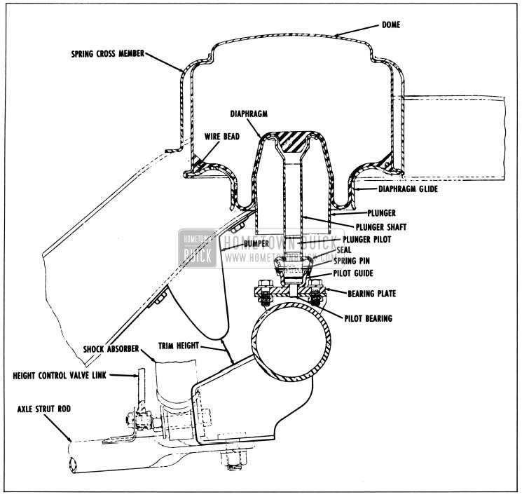
1958 Buick Air Springs
1958 Buick Air springs are located in the same position as coil springs on other models.
1958 Buick Rear Air Spring Mounting
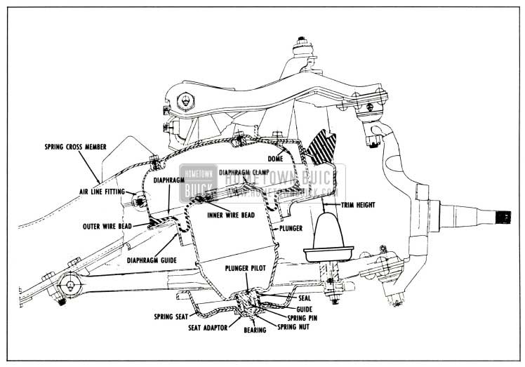
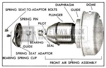
They are air chambers consisting of metal containers, called domes, into which rubber diaphragms are positioned at the bottom. The diaphragms are compressed by means of specially shaped plungers which are below the diaphragms and connected to the suspension. See Figure 7-34.
1958 Buick Air-Poise-Front Suspension
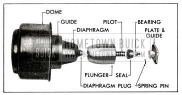
The domes are stampings with air fittings welded into the sides. The diaphragms are then positioned into the domes with diaphragm guides placed up and against the diaphragms. Then the lips of the domes are crimped over to securely hold the guides in position and form an assembly.
Diaphragms are rolling seals made of two-ply nylon cord with a layer of natural rubber vulcanized on the inside and a layer of ozone resistant rubber vulcanized to the outside. Both front and rear spring diaphragms pave a bead containing a wire at the outer edge, but only front diaphragms have a bead around an opening in their centers. The front diaphragms are held to the plungers by six cap screws and a diaphragm retainer clamp. Front plungers are hollow and have an opening at top to match the diaphragm opening and allow for flow of air into or out of the plunger. The rear diaphragms are solid at the center and incorporate a plug in their design which centers and holds the diaphragm to the solid rear plunger. See Figure 7-35.
1958 Buick Rear Air Poise Suspension Spring Assembly
At the very bottom of each plunger, both front and rear, is a plunger pilot, which is secured to a pilot guide by a spring pin. The pilot rides on top of a spherical bearing which is down in the pilot guide. A seal is positioned over the guide and pilot to exclude dirt, etc. The bearings handle all angular motion of the air springs.
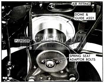
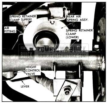
The bottoms of the rear pilot bearings fit into a hole in a bearing plate. The plate itself is bolted to a bracket on the rear axle housing. Pilot bearings on the front springs are retained to a spring seat adapter by a spring nut. See Figure 7-36.
1958 Buick Air-Poise-Rear Suspension
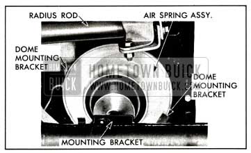
Rear air spring assemblies are held to the rear cross member by two self-tapping screws and two clips. One clip is welded at the top of the dome and the screw secures the clip to the cross member. The other clip butts under the dome lip and is secured to the side rail by the screw. Front air spring domes have two tapped fittings welded to the top and are held to the front cross member by two cap screws. See Figure 7-34.
Diaphragms cannot be replaced separately. The rear air spring dome, diaphragm and diaphragm guide are serviced as one assembly. On front air springs, the plunger is also included in the assembly.
1958 Buick Rear air spring assemblies used on 49-69 models are different in size from others and are not interchangeable with them.
1958 Buick Rear Spring and Valve Assembly
The normal pressure within the air springs is approximately 100 psi. As car weight load is increased, the height control valves allow more air to enter the springs so that trim height remains constant. Pressure within the springs then goes up. The reverse takes place when decreasing load weight.
Return Flow Control Orifice
As previously mentioned, the return flow control orifice is located in the manual override valve on the exhaust side. As air exhausts from the air springs under certain conditions, such as unloading the car, it flows through the exhaust, or return lines, to the override valve and through the return flow control orifice. This orifice allows only a gradual flow from the return lines to the atmosphere. Once through the orifice, the air flows to a tee fitting and then to either the compressor or the air cleaner.
Thus, some back pressure is retained in the exhaust lines to give additional control when rounding curves, during braking or when accelerating.
For instance, when rounding a long curve at high speeds, the weight would be thrown outward to the outer springs and would lessen on the inner springs. The height valves would level the car if some assistance were not available, and then would have to retrim after the turn had been made. The return flow control orifice gives this assistance by holding the pressure in the exhaust lines for a limited time whenever a height control valve exhausts air. This back pressure slows down flow through the exhaust valves during turning, braking and accelerating, thereby greatly reducing undesirable trimming.
7-20 1958 BUICK AIR-POISE SUSPENSION TROUBLE DIAGNOSIS
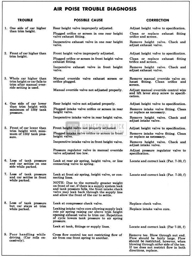
1958 Buick Air-Poise Trouble Diagnosis
Hard Ride Complaint
- Check the trim height and correct if necessary.
- Check the 1958 Buick shock absorbers for proper action and control.
- Inspect the rubber compression bumpers for damage. Replace if necessary.
- Check the operation of the height control valves. See Par. 7-23.
- If height control valves do not raise the car when weight is applied or lower the car when weight is removed, check the operation of the manual override valve pressure regulator. If the supply pressure is not between 135 and 145 psi, adjust the valve, or replace if necessary, to bring the supply line pressure to a recommended 140 psi. (Par. 7-23, b). The minimum pressure in the air tank should be 150 psi when checking the pressure regulator.
- If the pressure regulator is working properly and the air tank pressure is at least 150 psi, the trouble is probably in one of the height control valves.
1958 Buick Height Complaint
- Before adjusting height valve position, be sure that the manual lift control knob is pushed in and that the Bowden control wire is properly adjusted at the manual override valve.
- Disconnect the manual override valve to compressor inlet tee hose at the override valve. Then loosen the return flow control orifice nut on the override valve. If a large quantity of air exhausts and the car lowers to a normal trim height, then the return flow control orifice should be cleaned or replaced if necessary.
- If the front end or one rear corner is up and will not lower to trim height by adjusting the height control valves, then that height control valve is at fault. Remove the valve and inspect it by removing the cover. Observe the action of the valve cores. A weak or broken torsion spring will prevent either or both valve cores from opening. See Par. 7-22 (c).
Poor Handling Complaint
- If the car rolls excessively, remove and inspect the cross flow control tee which is located to the rear of the front height control valve. Blow into the nut end of the valve and feel whether the flow of air is good. Then blow through each side of the tee and this should give a restricted flow. Replace the valve if not operating properly.
- When 1958 Buick Air-Poise Suspension is functioning properly, there will be very little trim correction when cornering. The heavier the load, the less the correction while in a turn. If the manual override valve pressure regulator is set too high, the car will lean slightly when coming out of a curve. A return flow control orifice that is not restricting return air flow at all will have the same effect to a lesser degree. If the override valve pressure regulator is set too high, adjust to proper pressure or replace if necessary. If the return flow control orifice is at fault, repair or replace if necessary.
- If the car leans in one direction when driven for a few miles and will settle to correct trim height when the car is stopped, check the supply line pressure for a high reading, which would be caused by the override valve pressure regulator being set too high or not operating properly.
- If trim height corrections take place after a hard brake application, inspect the return flow control orifice at the manual override valve to be sure it is working properly. To check operation, disconnect the return pressure hose at the compressor inlet tee and add at least a one-passenger weight load. Allow time for the car to raise to normal height, then remove the weight load. Then listen to the air exhausting from the disconnected hose. If the return flow control orifice is working properly, inspect the front suspension for excessive friction. Lubricare the front suspension if necessary.
- If the front end lowers excessively after prolonged periods of acceleration. Check the operation of the cross flow control tee. See sub. par. a-3 (a).
NOTE: It is normal for a slight amount of trim correction to take place after prolonged periods of braking or acceleration.
Slow Trimming Complaint
Check air tank pressure. If tank pressure is generally low, make a compressor output check as follows:
- Start engine and set speed at 1500 RPM.
- Check air pressure at upper air tank fitting. If pressure is over 150 psi, release air until pressure is below 150 psi.
- When pressure gauge hits 150 psi, start timing compressor. Pressure should rise from 150 psi to 200 psi in 2% minutes or less.
- If pressure does not rise at specified rate, compressor pumping capacity is low. Check for a clogged suction hose or pipe. Check for leaks in high pressure hoses or fittings. If they are okay, next remove heads and check each reed valve for proper seating. Replace intake valves if necessary. If an exhaust valve is defective, the complete head and valve assembly must be replaced.
If no defective valves are found, compressor must be removed and overhauled.
Air Leak Checking Procedures-Internal
An internal leak is caused either by the manual override valve losing air from the pressure to the exhaust side (past override valve plunger) or by one or more of the height valve exhaust cores leaking. Check for an internal leak as follows:
- Make sure manual lift control knob is pushed fully in. With car at trim height and engine not running, disconnect return hose at compressor inlet tee and use bubble solution in end of hose. NOTE: This must be done without any weight change on car. If weight is added, such as by leaning on fender, and then remove, height valves would automatically exhaust air.
- If hose does not blow bubbles, there are no internal leaks. Proceed to check for external leaks as described in subpar. f below.
- If hose blows bubbles, make sure that manual override control wire is correctly adjusted so that stop screw on override lever is against stop (lever in fully down position). If necessary, adjust control wire according to procedure in paragraph 7-23 (c). Then recheck for leak at exhaust hose, making sure no car weight change takes place while checking.
- If return system still leaks, disconnect air return line at each height valve and use bubble solution on exhaust fittings (exhaust fitting is short fitting nearest cover plate). If an exhaust core leaks, height control valve must be removed from car for repair and internal adjustment. See paragraph 7-22 (b).
- If exhaust valve cores in all height valves are okay, but return system still leaks, manual override valve seat is leaking. Try backing out override lever stop screw slightly; if leaking still continues, override valve must be removed for repair. See paragraph 7-22 (c).
Air Leak Checking Procedures-External
After performing the above procedure and the internal system is free of leaks, check for external leaks by applying bubble solution on all joints and fittings. Correct any leaks found.
- Front end leak check (front end goes clown).
- Bubble check both front spring diaphragms at space between rubber diaphragm and metal diaphragm guide (preferably while in override position so that bubble solution may bridge gap between diaphragm guide and diaphragm). Also check at crimped seam between guide and dome. If leak exists replace air spring assembly.
- Check fitting at each air spring.
- Check three fittings at cross flow control tee at front height control valve, also where tubing is soldered to tee.
- Check all front height valve connections, edge of cover and around valve lever pivot shaft.
- Check all connections at manual override valve. To check relief valve, car must be in override position.
- Check all reservoir tank fittings and high pressure hose connections.
- Disconnect check valve assembly at compressor and bubble check disconnected end of check valve. If leak exists replace check valve.
- Check all supply line fittings starting at manual override and ending at intake fitting of both front and rear height control valves.
CAUTION: Even after finding an external air leak, continue to check all points listed as there may be more than one leak.
- Rear end leak check (one or both rear air springs goes down).
- Bubble check air spring diaphragms at space between rubber diaphragm and metal diaphragm guide preferably while in override position to close gap between diaphragm guide and diaphragm. Also check at crimped seam between diaphragm guide and dome. If leak exists replace air spring assembly.
- Check fitting at each air spring.
- Check all rear height valve connections, edge of cover and around valve lever pivot shaft.
- Check three connections at supply line tee mounted on rear spring cross member.
- Check all connections at manual override valve.
- Check all reservoir tank fittings.
- Disconnect check valve assembly at compressor and bubble check disconnected end of valve. If leak exists, replace check valve.
- Check all supply line fittings starting at manual override valve and ending at intake fittings of both front and rear height control valves.
CAUTION: Even after finding an external leak, continue to check all points listed under rear end leaks as there may be more than one leak.
7-21 REMOVAL AND INSTALLATION OF 1958 BUICK AIR-POISE SUSPENSION ASSEMBLIES
1958 Buick Front Air Springs
- Removal
- Jack up front of car at center of spring cross member.
- Place floor stands under front of frame side rails and then lower the jack.
- Remove tire and wheel assembly.
- Remove the air spring dome outer attaching bolt which is on top of the cross member and below the cutout in the upper control arm. Remove the other bolt which is approximately six inches toward center of cross member from first. See Figure 7-39.
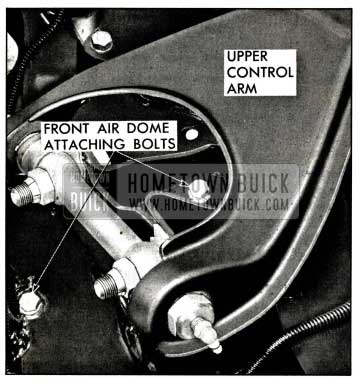
1958 Buick Front Air Dome Attaching Bolts
1958 Buick Front Air Spring Assembly
1958 Buick Front Height Valve Assembly
- Position air spring assembly up into cross member opening.
- Raise lower control arm assembly into position and install lower ball joint stud in steering knuckle (par. 7-11).
- Position plunger pilot bearing into hole in spring seat adapter and secure with spring nut.
- Place jack under spring seat, but do not raise car off floor stands.
- With one man below to position and hold spring up, and another on top, replace dome bolts and lock washers and tighten. See Figure 7-39.
- Connect air line to fitting at air dome using new sealing ring.
- Connect stabilizer bar link to lower control arm.
- Fill air tank at filler fitting with available air pressure.
- Operate height control valve link to pressure air spring.
- Use bubble solution at air line fitting to check for leaks.
- Connect height valve link to clamp-bracket on stabilizer bar. See Figure 7-41.
- Remove jack from spring seat and position at center of spring cross member. Raise car and remove floor stands. Lower and remove jack.
1958 Buick Rear Air Springs
- Removal
- Jack up car at center of axle housing and place floor stands under frame side rails.
- Lower jack and allow axle assembly to lower close to a full rebound position.
- Disconnect height control valve link at axle strut rod on spring being removed. See Figure 7-42.
1958 Buick Rear Height Valve Assembly and Bearing Plate
1958 Buick Rear Air Poise Spring Assembly
- Reverse steps (g) through (d) used in removal.
- When connecting air line at dome fitting, use new sealing ring.
- Before connecting height valve link to strut rod, raise height valve lever carefully to allow air to inflate air spring assembly.
- Use bubble solution and check at air dome fitting for leaks.
- Reverse steps (c) through (a) used in removal.
CAUTION:
- Never disconnect radius rod or torque tube unless all air is exhausted from rear air springs, as damage to air springs may result.
- Always disconnect height valve links at axle strut rods first if shock absorbers are to be disconnected.
- Never replace a 1958 Buick Air-Poise shock absorber with a standard shock absorber as the greater extended length of the standard shock absorber would cause damage to the air spring.
1958 Buick Front Height Control Valve
CAUTION: Never force any height control valve lever hard against its stop in either direction; this would bend the inner valve operating lever and throw off the valve setting.
- Removal
- Exhaust all air at drain petcock on air tank.
- Jack up front of car at center of spring cross member.
- Place floor stands under front of frame side rails and remove jack.
- Disconnect height valve link at clamp bracket on stabilizer bar. See Figure 7-41.
- Remove front spring cross member lower cover.
- Disconnect all air lines at height valve allowing cross flow control tee to remain with air lines. See Figure 7-41.
- Remove two valve bracket mounting bolts at front of cross member and remove bracket and valve assembly.
- Remove bracket from height valve.
- Replacement
- Reverse steps (h) through (f) used in removal. Use new O-rings at all air line fittings. (b) Before replacing spring cross member lower cover.
- Fill air tank at filler fitting with available air pressure.
- Operate height valve link slightly to pressurize front springs.
- Use bubble solution at air line connections on height valve to check for leaks.
- Reverse steps (e) through (a) in removal.
- Check valve operation by applying weight to front bumper.
- Reverse steps (h) through (f) used in removal. Use new O-rings at all air line fittings. (b) Before replacing spring cross member lower cover.
1958 Buick Rear Height Control Valve
- Removal
- Jack up car at center of axle housing to desired working height.
- Use a block 1/2″ shorter than normal trim height and position between frame and axle housing. See Figure 7-44.
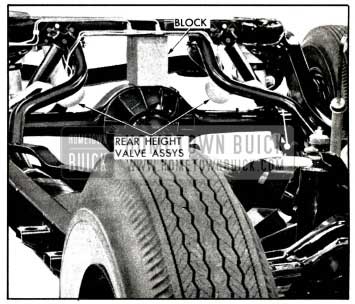
1958 Buick Blocking Up Body
- Reverse steps (g) and (f) used in removal. Use new O-rings at all air line fittings. (b) Fill air tank at filler fitting with available air pressure.
- Raise height valve lever to fill air spring and valve body.
- Check all air fittings on height valve with bubble solution.
- Connect height valve link to valve lever. (f) Reverse steps (c) through (a) in removal.
- Check trim height and correct if necessary.
- Check valve operation by applying weight to rear of car.
Manual Override Valve
- Removal
- Exhaust air out of air tank at drain petcock.
- Jack up car at center of front spring cross member to desired working height.
- Disconnect all air lines at override valve. See Figure 7-45.
1958 Buick Manual Air Pose Override Valve
- Reverse steps (f) through (b) in removal, using new O-rings at all fittings.
- Fill air tank at filler fitting with available air pressure.
- Check the adjustment of the bowden control wire to insure correct lift action (par. 7-23, c).
- Operate lift control on dash to put car into lift position.
- Use bubble solution at all override valve fittings and check for leaks.
- Release lift control to lower car to normal trim height.
1958 Buick Air Poise Air Compressor-Power Steering Pump Assembly
1958 Buick Air Compressor-Exploded View
- Removal
- Exhaust air out of air tank at drain petcock.
- Loosen the vented pulley nut and remove.
- Remove compressor belt and pulley.
- Disconnect power steering pump hoses. (e) Remove air inlet tee at compressor.
- Remove high pressure hose and check valve at compressor.
- Disconnect compressor-pump assembly from brackets and remove from car.
- Remove oil from reservoir.
- Remove the two compressor to pump bolts. Unless pump seal is to be replaced, install two Guide Pins J-7003 (3/8-16 x 3) in compressor to avoid damage to seal. Separate compressor from pump.
- Replacement
- Install two Guide Pins J-7003 (3/8-16 x 3″) in compressor.
- Carefully align pump on guide pins to avoid damage to seal and push into contact with compressor. Remove pins and install two compressor-to-pump bolts. Tighten to 25-30 ft. lbs. torque.
- Mount compressor-pump assembly in brackets. Install but do not tighten bolts.
- Connect high pressure hose and check valve to compressor.
- Connect inlet tee at compressor.
- Connect power steering hoses to pump.
- Install compressor pulley and belt.
Securely tighten vented pulley nut. - Adjust belt tension and tighten mounting bolts. Tension should be 30 to 35 ft. lbs. torque on pulley nut to slip old belt (40 to 45 ft. lbs. torque to slip new belt).
- Fill reservoir to the proper level with Dynaflow oil, run engine and check for leaks. Do not remove reservoir cover when engine is running above idle speed.
CAUTION: Since the compressor is dependent upon the power steering oil pump for lubrication, it is most important that reservoir oil level be at full mark at all times. After replacing compressor-pump assembly and running engine, check oil level with engine idling and add oil as needed. Also check compressor oil pump by observing flow at oil return standpipe (par. 7-22, b).
7-22 DISASSEMBLY, ASSEMBLY AND ADJUSTMENT – 1958 BUICK AIR-POISE SUSPENSION ASSEMBLIES
Compressor and Pump Assembly
- Disassembly
- Remove all foreign material from exterior of compressor using wire brush and air hose.
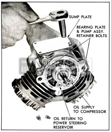
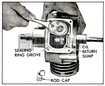
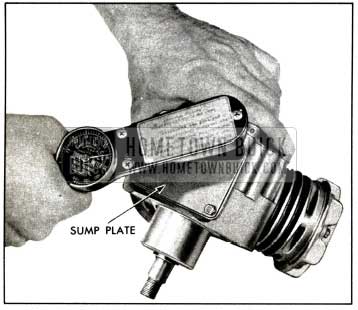
- Invert compressor and remove four bolts and lock washers which retain sump cover plate to block. See Figure 7-47.
1958 Buick Remove Sump Plate
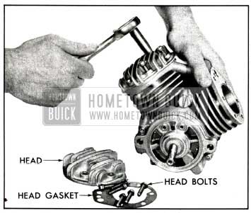
1958 Buick Remove Cylinder Heads
1958 Buick Remove Rod Bolts and Caps
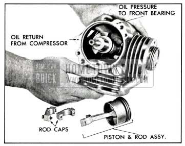
1958 Buick Remove Pistons and Rods
1958 Buick Piston and Rod Assembly
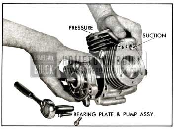
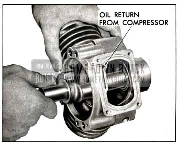
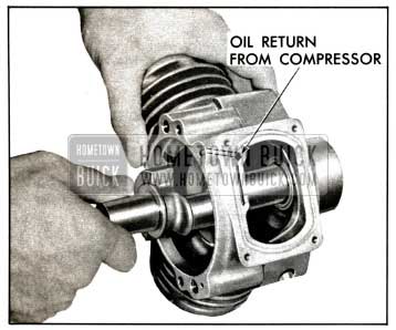
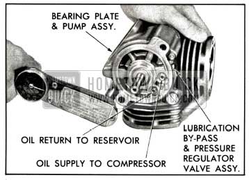
1958 Buick Remove Bearing Plate and Pump Assembly
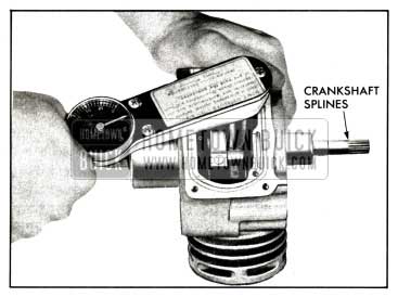
1958 Buick Remove Crankshaft
1958 Buick Remove Front Oil Seal
- Wash all metal compressor parts in a suitable solvent and blow them dry with air. Inspect all parts, openings and passages to be sure they are open and clean.
- Inspect the front seal bore for any roughness or scores. Any such damage should be dressed down before installing a new seal.
- Install a new seal in bore using Seal Installer J-7079. Install flush with top of bore. See Figure 7-55.
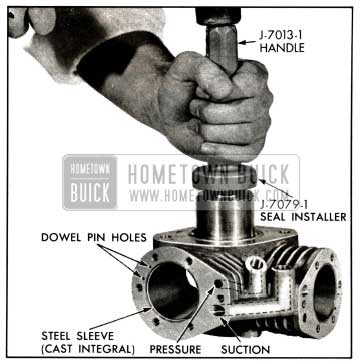
1958 Buick Replace Front Oil Seal
1958 Buick Install Crankshaft
1958 Buick Install Bearing Plate and Pump Assembly
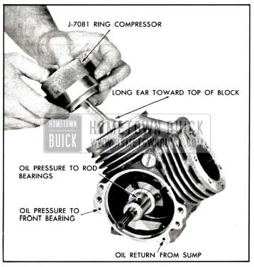
Install the assembly into the bore with the long ear of connecting rod toward the top of the block. See Figure 7-58.
1958 Buick Install Piston and Rod Assembly
1958 Buick Compressor-Install Rod Caps
1958 Buick Compressor-Install Sump Cover Plate
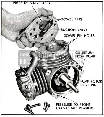
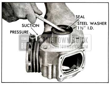
1958 Buick Compressor-Install Head and Suction Valve
1958 Buick Compressor-Head Bolt Tightening
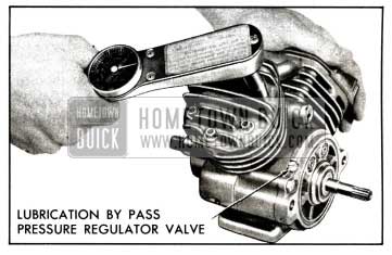
1958 Buick Compressor Oil Pump
- Testing Oil Pump Pressure
The oil pump pressure may be checked accurately by removing the test plug (figure 7-66), connecting a suitable pressure gauge, and running the engine at idle.
However, a satisfactory test may be made by simply removing the reservoir cover with the engine idling. The oil return standpipe (pipe nearest center of car) should have oil and air welling out. Observing the action at this standpipe in a known good job will give a standard for comparison.
CAUTION: Never run the engine faster than idle speed while the reservoir cover is removed or returning oil will spray the engine compartment.
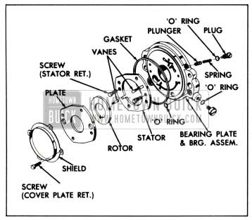
1958 Buick Bearing Plate and Pump Assembly
- Disassembly of Oil Pump
Whenever the oil pump pressure or flow is not satisfactory, the pump must be disassembled at follows:
- Remove bearing plate and pump assembly.
- Bend back tabs of pump shield to gain access to retaining screws. Remove four retaining screws.
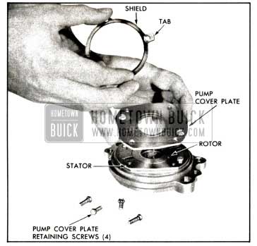
1958 Buick Removing Pump Shield and Cover Plate
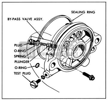
1958 Buick Installing By-Pass Valve and Test Plug
- Adjustment and Assembly of Oil Pump
- Wash all metal parts in solvent and blow out oil passages to remove any dirt particles or foreign matter. Blow parts dry.
- Replace test plug with a new O-ring. Replace by-pass valve plunger, spring and plug using a new O-ring. See figure 7-66.
- Position pump stator on bearing plate with six mounting holes aligned.
- Install two stator retaining screws finger tight in locations shown in figure 7-65.
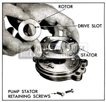
1958 Buick Removing Pump Rotor and Stator
Bend tabs of pump shield up in lock position.
CAUTION: If pump fails to produce in a few minute s, shut engine off. Recheck pump assembly.
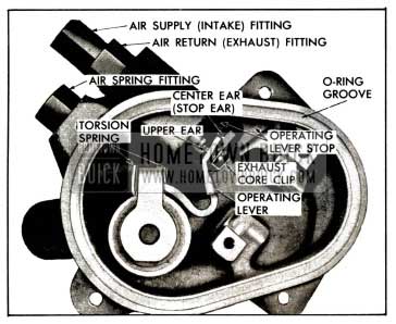
1958 Buick Height Control Valves
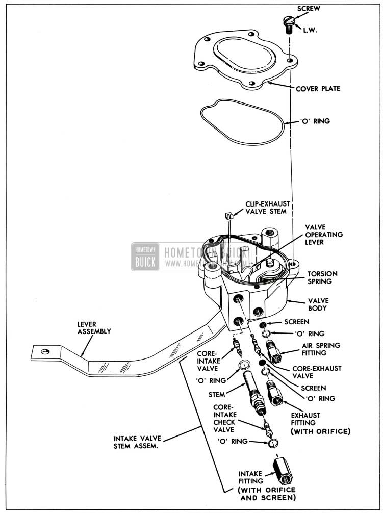
1958 Buick Height Control Valve-Exploded View
- Disassembly
- Remove the cover screws, cover and O-ring.
- Remove sealing rings from the three line fittings.
- Remove intake fitting, valve stem, and O-rings.
- Remove exhaust and air spring fittings and screens under these fittings.
- Remove the valve stem.
- Remove the three O-rings from the fittings and valve core stem.
- Remove the copper stop clip from the exhaust valve core. Use a fine pair of needle nose pliers to hold the core stem and then pull the clip loose from the stem end with needle nose pliers. Care must be used so that the stem is not bent.
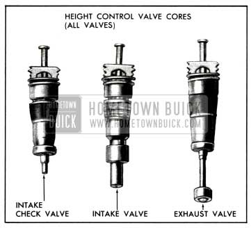
- Remove the exhaust valve core from the valve body, the intake valve core from the bottom of the intake valve stem and the intake check valve core from the upper end of the valve stem. Use J-6888 for removal of all three cores. See Figure 7-68.
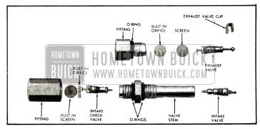
1958 Buick Height Control Valve-Valve Cores and Fittings
- Clean all parts in a suitable solvent and inspect. Do not use a solvent that will injure rubber since the seal at the lever shaft will be affected.
- Use new O-rings at all points.
- Install the intake check valve at the top of the valve stem and the intake valve at the bottom of the stem. Install the exhaust valve into the height valve body. Tighten all three valves using J-6888. See Figure 7-69.
1958 Buick Height Control Valve-Cores
1958 Buick Height Valve Fittings
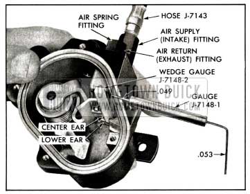
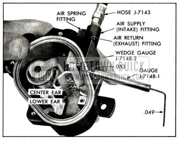
- Connect hose J-7143 to an air pressure line and reduce the line pressure to 10-20 psi. Do not exceed 20 psi. Install the other end of Hose J-7143 at the air return exhaust fitting and tighten.
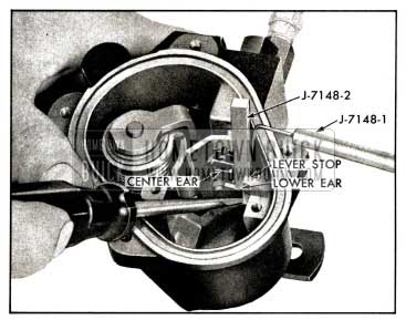
- Place the .049 side of Gauge J-7148-1 between the operating lever stop, (on the side furthermost from the valve cores) and the middle ear of the operating lever. Insert Wedge Gauge J-7148-2 between the other side of the stop and lever ear and press down securely. Gauge J-7148-2 is a wedge and should hold the feeler gauge so that it does not fall out. See Figure 7-71.
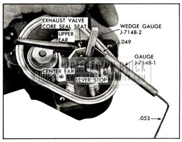
1958 Buick Checking Exhaust Valve
1958 Buick Checking Air Pose Exhaust Valve
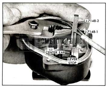
1958 Buick Setting Exhaust Valve
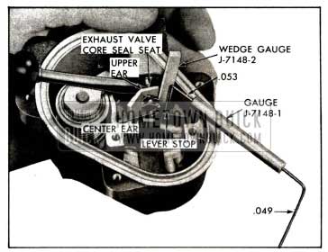
Use the screwdriver or other suitable tool and once more press in to seal the core seat. If the bending performed was sufficient, no air leakage should be heard. If leakage is still heard, then the upper ear was not moved enough. If no leakage is heard, remove Wedge Gauge J-7148-2 and Gauge J-7148-1 and repeat Step (2) using the .049 end of the gauge. A slight amount of leakage should be heard. See Figure 7-73.
1958 Buick Checking Intake Valve
1958 Buick Setting Intake Valve
1958 Buick Checking Air Pose Intake Valve
Install the height valve.
Manual Override Valve
- Disassembly
- Remove lever spring from the bracket and manual lever.
- Remove dust boot. Remove 3 screws retaining Bowden control wire bracket. Remove bracket. See Figure 7-77.
1958 Buick Manual Override Valve – Exploded View
Remove hexagonal plunger from valve body.
- Inspect all parts and clean with a suitable solvent. Blow dry with a low pressure. The seal on the valve stem is very critical as are other rubber parts. Therefore, replace all rubber parts and also any other parts that appear doubtful.
- Insert plunger into valve body with groove located to receive cam.
- Install new O-ring on cam and install cam with pin on the end matching up with groove in plunger. Use silicone rubber lubricant on O-ring. Flat side of cam shaft should be up. See Figure 7-77.
- Install snap ring, using No. 1 Truarc Pliers. Install manual lever on cam. Secure lever with set screw.
- Install new gaskets at seat plate. Install a gasket into body, then plate and then other gasket.
- Install exhaust spring and new screen. See Figure 7-77.
- Install retainer into valve body and tighten.
- Install new valve stem into lower cavity of body and install retainer spring and retainer into upper cavity. Place tool J-7085 over stem and turn clockwise while holding stem retainer stationary with No. 1 Truarc Pliers. Tighten securely.
- Install filter retainer.
- Install new diaphragm in upper cavity of body being careful to center diaphragm.
- Install adjusting screw into housing. Allow screw to extend out at top of housing the same distance as was measured before removing screw.
Position regulator spring into housing against adjusting screw. - Install piston over regulator spring.
- Install housing assembly and bracket on valve body. Edge of diaphragm must show evenly in all four screw holes of housing or diaphragm is not centered. Install 4 screws. Tighten securely.
- Install return spring on bracket and manual lever.
- Install dust boot over housing.
NOTE: After installing manual override valve on car, it must be adjusted so that correct supply line pressure is obtained. Refer to par. 7-23 (b).
1958 Buick Rear Air Springs
- Disassembly
- Push seal up on plunger pilot so that spring pin in guide can be seen.
- Use a drift pin of correct size and drive spring pin out of guide and plunger pilot. See Figure 7-78.
1958 Buick Rear Air Poise Suspension Spring Assembly
- Clean and inspect all parts.
- Reverse steps used in disassembly.
- Lubricate bearing with all purpose lithium grease before assembling.
NOTE: On rear springs, the air dome, guide and diaphragm are replaceable as an assembly only. The plunger and pilot form another assembly.
1958 Buick Front Air Springs
- Disassembly
- Slide seal off guide.
- Use a drift pin of correct size and drive spring pin out of guide and pilot. See Figure 7-79.
1958 Buick Front Air Poise Spring Assembly
- Clean and inspect all parts.
- Reverse steps used in disassembly.
- Lubricate bearing with all purpose lithium grease before assembling.
NOTE: On front springs, air dome, guide, diaphragm, plunger and plunger pilot are serviced as an assembly. If any one part of assembly should fail, complete assembly must be replaced.
7-23 1958 BUICK AIR-POISE SUSPENSION ADJUSTMENTS ON CAR
Checking and Setting Trim Heights
- Check the operation of the 1958 Buick height control valves by applying weight to each side of the rear bumper, one side at a time, and to the center of the front bumper. The car should raise back to normal trim height after weight has been added and should lower to the proper height after the weight has been removed.
- Check and correct tire pressures and inspect for any binding anywhere in the suspension system. Correct if necessary.
- Check 1958 Buick shock absorber action by comparing its action with that of a known good shock absorber.
- Drive the car on a front end alignment rack. There is a “neutral zone” in every height control valve; that is, a dead spot where some movement of the height valve arm is possible without opening either the exhaust or intake valve. To .eliminate the variation in trim height caused by this “neutral zone”, always manually trim the car by pulling down on the frame until air enters the air spring. Then gradually release the downward pull, allowing the car to retrim.
- To check rear trim heights, check the distance between the tip on the bottom of the rear compression bumper and the bumper bracket directly below the compression bumper. Distance should measure 1 5/8″, plus or minus 1/4″, on all models except the 49 and 69. The distance should measure 1 1/4″ plus or minus 1/8″ on the 49 and 69 models. Repeat check on the other side. See Figure 7-80.
1958 Buick Rear Trim Height
See Figure 7-81.
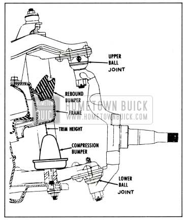
1958 Buick Front Trim Height
- If trim settings are not correct, loosen the two nuts and bolts at the link clamp-bracket on the front stabilizer bar. Rotate the clamp-bracket in the correct direction and tighten both nuts and bolts. Recheck trim height settings once more.
Checking and Setting Supply Line Pressure
- Bring air tank pressure up to 200 psi minimum.
- Disconnect the air return line on the top of the manual override valve and install hose J-7143 in the valve fitting.
- Pull the manual lift knob, which is inside the car at the right dash panel, to put the car into the lift position.
- Press Gauge J-6840 on the end of Hose J-7143 and take a reading. Remove the gauge.
- If pressure is more than 145 psi, remove the boot from the override valve and turn the adjusting screw out (counterclockwise) 1/2 turn at a time.
- Depress the Schrader core in the end of the hose for five seconds and then take another gauge reading.
- If the reading is still too high, repeat the procedure until correct reading is obtained. If valve cannot be adjusted, remove the valve and disassemble.
- If the pressure is less than 135 psi, turn the pressure adjusting screw in (clockwise) 1/2 turn and then take a gauge reading. Repeat the procedure until the correct reading is obtained.
- If the correct reading cannot be obtained, remove the override valve and disassemble.
NOTE: Any time an override valve is to be disassembled, measure the height of the pressure adjusting screw that extends out of the housing. Then after assembling, position the screw at the same height and follow the procedure for checking and setting supply line pressure.
- Push the manual lift knob all the way in to lower the car to normal trim height.
- Depress the Schrader core in the hose to exhaust all air from the hose and then remove the hose.
- Connect the air return line at the override valve using a new sealing ring, and pull the manual lift knob to put the car into the lift position. Use bubble solution at the fitting connection to check for leaks. Push knob in to lower car.
Checking and Adjusting Manual Override Valve Control Cable
If the manual override valve control cable is not in proper adjustment, the override plunger may not seat when the control knob is in the normal ride position and a constant air leak will result. See figure 7-82.
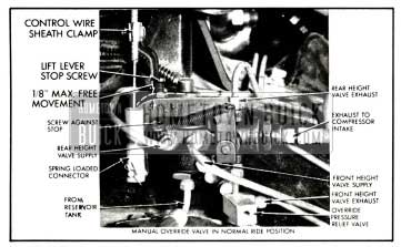
1958 Buick Manual Override Valve
Also, when the control knob is in the override position, incorrect adjustment may prevent the plunger from seating, resulting in an air leak. Check control cable adjustment as follows:
- Make sure override control knob is pushed fully in.
- On manual override valve, grasp control lever stop screw and lift lever lightly. If control cable is properly adjusted, lever should have a slight amount of free motion, but not over 1/8 inch. See Figure 7-82.
- To adjust override valve control cable, loosen conduit clamp screw.
- Slide conduit fully down and then raise it about 1/16 inch.
- Tighten conduit clamp screw and recheck adjustment as described above.
Checking and Adjusting Manual Override Lever Stop Screw
The control lever stop screw setting should never be changed without first checking the control cable adjustment as described in subpar. c above. If stop screw is against its stop and there is still an air leak past override plunger, try adjusting stop screw as follows:
- Note position of screw. Then loosen lock nut and back out screw until air just stops leaking. (If backing screw out does not cause air leak to stop, stop screw was not out of adjustment. Return screw to original setting and look elsewhere for trouble.)
- Now back out screw exactly two turns from this point and tighten lock nut.
7-24 JACK INSTRUCTIONS – 1958 BUICK AIR-POISE CAUTION
On 1958 Buick Air-Poise equipped cars, the manual lift knob must be pulled out so car is in the fully raised position before using bumper jack to raise car. After jacking operation is completed, manual lift knob must be pushed back firmly into the normal operating position before car is driven.
Leave A Comment
You must be logged in to post a comment.