SECTION 10-H 1958 BUICK SIGNAL SYSTEMS
10-52 1958 BUICK HORNS AND CONTROL CIRCUIT
1958 Buick Horns and Relay
Two Delco-Remy electrically operated vibrator type horns are mounted in front of the radiator. Both 1958 Buick horns are operated simultaneously by a horn relay which is controlled by the horn button on steering wheel. The left hand horn is high pitched and the right hand horn is low pitched, so that together they produce a pleasant blended tone.
The 1958 Buick horn relay is an electrical switch which closes the circuit between the battery and the horns when the horn button is pressed, and opens the circuit when the button is released. The relay permits control of the horns with a small amount of current passing through the horn button contacts. The high current required by the horns would cause arcing and burning of these contacts.
When the 1958 Buick horn button contacts are closed, a small amount of current flows through the relay winding to ground at the horn button. This magnetizes the relay core, which attracts the flat steel relay armature. The armature has a contact point which makes contact with a stationary point to close the horn circuit. When horn button is released, current stops flowing through relay winding so that the core loses its magnetism; the armature spring then causes contact points to be separated.
1958 Buick Horn Buttons
The 1958 Buick horn button used with the Series 40 standard steering wheel has a cap with a rubber retainer in its rim which snaps over the rim of a contact cup mounted in the wheel hub. The cap may be pried out with a thin bladed tool and the contact cup and other parts may then be removed by removing the attaching screws and insulating spacer bushings.
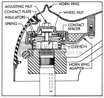
The 1958 Buick horn button used with the DeLuxe steering wheel has a large operating ring mounted over the wheel hub and spokes. To remove the horn operating parts, (1) remove the operating ring by removing three cross-recess screws from underneath, (2) unscrew and remove the adjusting nut, (3) remove the contact plate and spring, with the two insulators, (4) remove steering wheel nut, ( 5) remove contact spacer, cushion, and horn ring adapter. See figure 10-67.
1958 Buick Horn Operating Ring Installation
Install operating ring by reversing the procedure for removal. The steering wheel nut is self-locking and does not require a lockwasher. When the contact adjusting nut is being installed, turn it down until contact is made and horns blow, then back nut off %, turn to provide proper clearance between contact plate and spacer.
Adjustment of 1958 Buick Horns
When 1958 Buick horns fail to blow, first check wiring circuit (par. 10-12, c) and relay (par. 10-53) before attempting to adjust horns. If horns are at fault, or tone is poor, adjust each horn for specified current draw as follows:
- Remove 1958 Buick horn from car.
- Connect an ammeter in series with horn and a fully charged 12 volt battery to measure current draw while horn is blowing. Current draw for each horn (either high or low note) should be between 7 and 12 amperes at 12.0 volts.
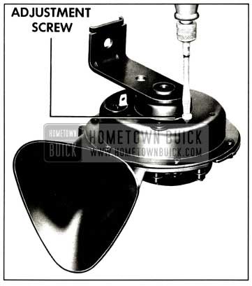
- Adjust to specified current draw if necessary, by turning adjusting screw clockwise to decrease or counterclockwise to increase current draw. See figure 10-68.
1958 Buick Horn Current Draw Adjustment
Increasing the current draw increases the horn volume. Too much current will cause a high cut-in voltage, which will cause a sputtering sound and may cause horn to stick in cold weather.
10-53 TROUBLE-SHOOTING 1958 BUICK HORN RELAY
There are two basic troubles which may be caused by a defective horn relay. If neither 1958 Buick horn will blow at all, this trouble may be caused by the relay points not making contact. Or if horns will not stop blowing, this trouble may be caused by relay points sticking.
To check for a defective horn relay follow the procedure in subparagraph a or b below.
1958 Buick Horns Will Not Blow
- Try eliminating 1958 Buick horn relay as cause of trouble by breaking circuit at connector on steering column jacket under instrument panel and grounding wire. If horns now blow, relay is OK, but horn control circuit in steering column jacket has an open circuit. Reconnect wire on jacket connector and check horn button contacts.
- If horns still do not blow, unplug 3-way connector from horn relay which is mounted on left fender skirt below generator regulator. Then plug a known good relay onto the connector. There is no need to ground new relay-just let it hang from connector. CAUTION: Horn relay is identical with Safety-Minder buzzer unit in appearance except that buzzer unit has a resistor, one end of which is spot-welded to mounting bracket.
- If 1958 Buick horns will now blow, old relay is defective and must be replaced. However, if horns still will not blow with substitute relay, trouble is elsewhere than at horn relay. See paragraph 10-12.
1958 Buick Horns Will Not Stop Blowing
- Pull wire from connector on jacket as in step 1 above. If 1958 Buick horns stop blowing, relay is OK, but horn control circuit in jacket is grounded. See paragraph 10-12 (c).
- If horns still do not stop blowing, unplug 3-way connector from horn relay as in step 2 above. Then plug a known good relay onto the connector.
- If horns now stop blowing, old relay contacts are sticking and relay must be replaced. However, if horns still do not stop blowing, control circuit is grounded between relay and connector on jacket.
10-54 1958 BUICK DIRECTION SIGNAL LAMPS AND SWITCH
1958 Buick Direction Signal Lamps and Indicators
The 1958 Buick front direction signal light is produced by the 32 CP filament in the bulb mounted in the front parking lamp. The rear direction signal light is produced by the 32 CP filament in the bulb in the center section of the rear lamp assembly. This filament also serves as a stoplight.
When the ignition switch is turned on and the 1958 Buick direction signal switch is manually operated to indicate a turn, the front and rear signal lights flash on and off on the side of car for which a turn is indicated. The flashing of 1958 Buick signal lights is caused by a flasher which is connected into the proper signal circuit by contacts made in the direction switch when switch is set for a turn. There are two circuits within the flasher; one supplies impulses for the front and rear signal lights on either side, and the other circuit supplies impulses for either indicator bulb on the instrument panel.
When the 1958 Buick direction signal lights are flashing, a signal indicator bulb on instrument panel also flashes, producing a small arrow of green light to indicate the direction for which the signal has been set.
Direction Signal Switch Operation
The 1958 Buick direction signal switch is mounted on the steering column jacket under the instrument panel. Its actuating mechanism is enclosed in a housing on the steering column just below the steering wheel. Movement of the actuating mechanism is transmitted to the signal switch through a Bowden wire which runs down the outside of the steering column jacket.
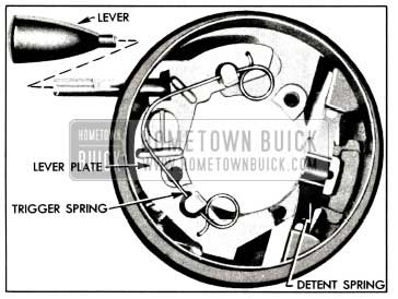
The control lever is threaded to screw into a lever plate. When the lever is moved up or down, it causes the lever plate to rotate around a pivot screw. This motion is transmitted to the Boden wire through a nylon bell crank which changes the rotating motion of the lever plate into lengthwise motion of the wire. A detent spring mounted in the housing bears against a nylon roller mounted on the lever plate to hold the plate in whatever position it may set. Bosses in the housing provide stops for the plate when set for either turn. See figure 10-69.
1958 Buick Direction Signal Actuator
The Boden wire has a loop in its lower end which engages a bakelite pin projecting from the under side of the sliding part of the 1958 Buick direction signal switch. The movement of the Boden wire and switch slide is not adjustable, therefore any adjustment must be made by moving the switch housing up or down the steering column jacket. See subparagraph d for the adjustment procedure.
The trip or cancellation mechanism for returning the switch to the “off” position after a turn is completed consists of a trigger spring on the lever plate and two switch centering pins on the steering wheel hub. The pins extend down through the lever plate, but when the switch is in the “off” position the lever plate is centered so that the pins cannot contact the trigger spring as the steering wheel is turned.
When the control lever is moved clockwise to set the switch for a right turn the lever plate is moved down, thereby moving the switch handle down and also bringing the upper loop of the trigger spring into the path of the centering pins. As the steering wheel is turned right and a centering pin contacts the trigger spring the spring yields to permit the pin to pass without interference. As the wheel is turned left at completion of the right turn, the centering pin pushes the loop of trigger spring against a stop on the lever plate, and this forces the lever plate and switch back to the “off” position.
A similar action but in the opposite direction takes place when the switch is set for a left turn. If the switch is erroneously set to indicate a turn in one direction and the turn is made in the opposite direction, the opposite centering pin will contact the trigger spring and return the switch to the “off” position as the wrong turn is started.
Trouble-Shooting 1958 Buick Direction Signal System
- No Signal Anywhere. If there is no signal at any front, rear, or indicator light, first check fuse on fuse block marked “DIR. SIGNAL”. Since this fuse also protects stop light system, functioning stop lights indicate that fuse is OK.
If fuse checks OK, next eliminate flasher unit by substituting a known good flasher. If new flasher does not cure trouble, check 1958 Buick signal system wiring connections at fuse block and at signal switch.
- Signals One Direction Only. If 1958 Buick signal works properly on one side, but there is no signal at front, rear, or indicator light on either side, adjust direction signal switch. See subparagraph d below. If trouble cannot be corrected by adjustment, replace switch.
- Signal Too Rapid One Direction. If there is an abnormally rapid signal at one light and other light does not light, check for a burnedout light bulb or an open circuit in wire to bulb not lighting.
When a front or rear signal bulb is burned-out, indicator light for that direction will flash once briefly and then remain off. This immediately notifies driver when any signal light quits operating.
1958 Buick Direction Signal Switch Adjustment
Whenever a 1958 Buick direction signal switch is installed, it must be properly adjusted. Incorrect adjustment of the switch is indicated if the direction signal system operates in one direction only.
The 1958 Buick directional signal switch is mounted on the steering column jacket under the instrument panel. It is actuated by a Boden wire from the actuator assembly on the upper end of the steering column. A loop in the lower end of the Boden wire fits over a pin which projects from the switch. The movement of the Boden wire is not adjustable, therefore any adjustment necessary must be made by moving the switch housing up or down the steering column jacket.
Adjust 1958 Buick direction signal switch as follows:
- Place direction signal control lever in center position.
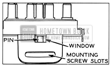
- Loosen two switch mounting screws and move switch up or down steering column jacket until pin projecting from switch is centered in window. See figure 10-70. Pin can be accurately centered by holding a light in back of switch while sighting through window. Tighten switch mounting screws.
1958 Buick Checking Direction Signal Switch Adjustment
1958 Buick Direction Signal Lamp Circuits
Since the 1958 Buick direction signal lights are independent of the headlamp lighting switch and thermo circuit breaker, the wiring circuits are protected by a “DIR. SIGNAL” fuse on the fuse block under the cowl. The flasher is also mounted on the fuse block, which serves as a terminal block between the 1958 Buick signal switch and the chassis wiring.
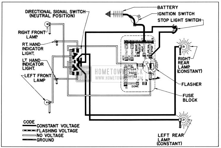
1958 Buick Direction Signal Lamp Circuit Diagram-No Turn Indicated
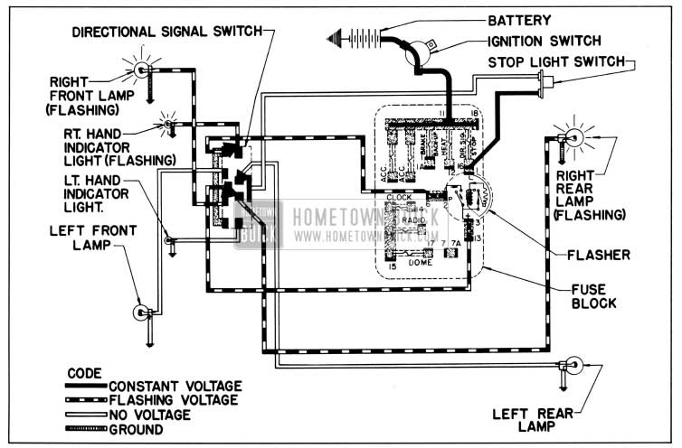
1958 Buick Direction Signal Lamp Circuit Diagram-Right Turn Indicated
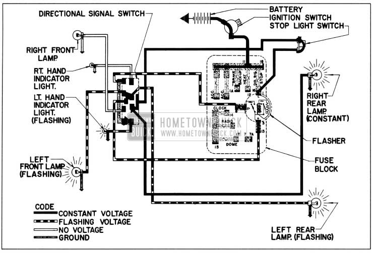
1958 Buick Direction Signal Lamp Circuit Diagram-Left Turn Indicated
Figures 10-71, 10-72, and 10-73 show the 1958 Buick direction signal circuits when signal switch is set for No Turn, Right Turn, and Left Turn. Direction signal switch wiring is also shown in the chassis wiring circuit diagrams in Section 10-J.
Leave A Comment
You must be logged in to post a comment.