SECTION 7-A 1958 BUICK CHASSIS SUSPENSION SPECIFICATIONS AND DESCRIPTION
7-1 1958 BUICK CHASSIS SUSPENSION SPECIFICATIONS
Tightening Specifications
Use a reliable torque wrench to tighten the parts listed, to insure proper tightness without straining or distorting parts. These 1958 Buick chassis suspension specifications are for clean and lightly lubricated threads only; dry or dirty threads produce increased friction which prevents accurate measurement of tightness.
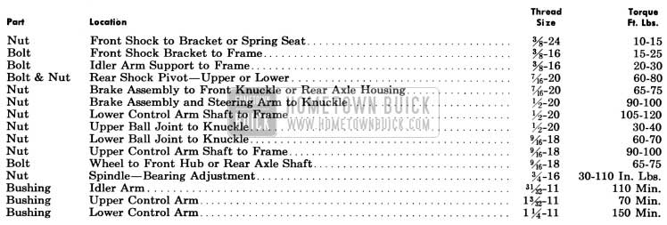
1958 Buick Chassis Tightening Specifications
1958 Buick Wheels and Tires
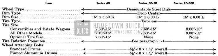
1958 Buick Wheels and Tires Specifications
1958 Buick Shock Absorbers
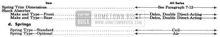
1958 Buick Shock Absorbers Specifications
1958 Buick Springs (see above)
Dimensional Specifications
NOTE: Dimensions and limits given in these specifications apply to new parts only. Where limits are given, “T” means tight and “L” means loose.
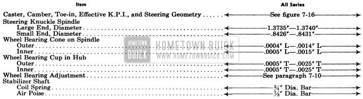
1958 Buick Chassis Dimensional Specifications
7-2 DESCRIPTION OF 1958 BUICK WHEEL SUSPENSION
1958 Buick Front Wheel Suspension
The 1958 Buick front wheel suspension allows each front wheel to rise and fall, due to change in road surface level, without appreciably affecting the opposite wheel.
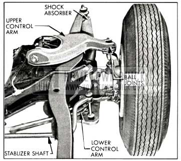
Each 1958 Buick wheel is independently connected to the frame front cross member by a steering knuckle, ball and socket assemblies, and upper and lower control arm assemblies. See figure 7-1.
1958 Buick Front Wheel Suspension
The upper and lower arms are so placed and proportioned in length that they allow each knuckle, and wheel to move through a vertical arc only. The front wheels are held in proper relation to each other for steering by means of two tie rods which connect to steering arms on the steering knuckles and to the intermediate rod.
A coil type chassis spring or an air spring is mounted between the frame front cross member and a spring seat in each lower control arm assembly. A large rubber bumper is mounted on the outer end of each lower control arm to limit travel of the arm during compression of chassis spring. A similar rubber bumper is mounted on the frame under each upper control arm to limit travel of arm during rebound of 1958 Buick chassis spring.
Side roll of the front end of chassis is controlled by a spring steel stabilizer shaft. The shaft is mounted in rubber bushings supported in brackets attached to lower flange of each frame side rail. The ends of stabilizer shaft are connected to the front sides of lower spring seats by links which have rubber grommets at both ends to provide flexibility at the connections and prevent rattle. See figures 7-1 and 7-8.
The lower control arm assembly consists of two drop forged steel arms solidly riveted to a stamped steel spring seat to form a rigid unit. A small plate above the spring seat serves as a mounting for a rubber bumper. Hardened steel threaded bushings are screwed solidly into the inner ends of the forged arms to provide thread-type bearings on the ends of the control arm shaft which is attached to the frame front cross member. The outer end of each arm is riveted to the socket portion of the ball and socket assembly which connects the steering knuckle to the lower control arm. The tapered shanks of the ball studs fit into matching tapered holes in the steering knuckles and are held in place by castellated nuts safe-tied with cotter pins. See Figure 7-2.
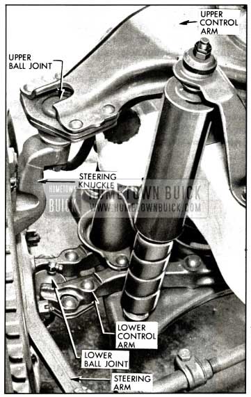
1958 Buick Left Steering Knuckle and Ball Joints
The upper control arm consists of a stamped and welded steel plate formed to provide maximum strength. Two replaceable hardened steel threaded bushings are screwed into the inner end of each assembly. A replaceable ball joint assembly is riveted to the outer end of each arm. The service ball joint is supplied in a kit which contains special bolts, nuts and lockwashers to replace the rivets. A bent or damaged upper control arm must be replaced as straightening is not practical.
Rubber seals are installed on upper and lower arm shafts to exclude dirt and water from the bearing surfaces. Lubrication fittings are provided at all bearing locations.
The ball joints which attach the steering knuckle to the upper and lower control arms also provide the bearing surfaces to withstand the thrust and turning loads. The steering: knuckle spindle supports the wheel hub with two New Departure adjustable cup and cone ball bearings. The outer end of hub is closed by a cap and inner end is sealed with a lip seal to exclude dirt and water from bearings. See figure 7-9.
During brake application two forces act on the front suspension. When the brakes are applied, the torque is transmitted to the backing plate and knuckle assembly through the brake shoes, which tends to rotate the backing plate and knuckle assembly forward. The weight of the car is thrown forward tending to move the front of the car downward. This downward motion is called “front-end dive”. In order to minimize “front-end dive”, the upper control arm shaft is mounted to the frame so that the front end of the shaft is higher than the rear end at an angle of approximately 14° relative to that of the lower control arm shaft. Thus, when the braking force is applied, the tendency of the car’s front end to dive rotates the backing plate and spindle assembly in a rearward direction, while the braking torque tends to rotate the backing plate and spindle assembly in a forward direction. Therefore, the braking torque creates an upward force nearly equal to the downward (diving) force. In this manner, “front-end dive” is held to a predetermined minimum. See Figure 7-1.
1958 Buick Rear Wheel Suspension
Rear wheels are not independently sprung since they are mounted on axle shafts incorporated in the rear axle assembly. The rear wheels are held in proper alignment with each other by the rigid construction of the rear axle housing. They are held in alignment with the rest of the 1958 Buick chassis by the torque tube and radius rod between car frame and the rear axle assembly.
Two coil type chassis springs or air spring assemblies are mounted between the frame cross member at top of kick up, and spring seats (for coil springs) or a special bracket (for air springs) are welded to the axle housing near the end. Ride control is provided by two identical double direct-acting shock absorbers angle mounted between brackets welded to the front of the rear axle housing and brackets bolted to the front of the rear spring cross member. Side sway of the 1958 Buick chassis springs and rear end of frame is prevented by the transverse radius rod. Large rubber bumper and rubber rear axle stops are bolted to lower flange of frame side rails over axle housing to limit travel of axle housing during compression of the 1958 Buick chassis springs. See figure 7-3.
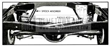
1958 Buick Rear Wheel Suspension
1958 Buick Wheels and Tires
1958 Buick wheels are demountable steel disk type. The wheels have wide drop center type rims designed to give ample support for the tire sizes used as standard equipment. The rims have a tapered tire bead seat on the inboard side and a hump-type bead seat on the outboard side which cause tire beads to wedge tightly in place when tires are inflated.
CAUTION: When mounting a tire on this type of wheel, it is imperative to apply mounting soap around the beads for ease of mounting and to prevent damage to the beads.
1958 Buick tires are tubeless low pressure balloon type, of 4-ply construction. U. S. Royal, Firestone, out optional selection of any specified make.
All 1958 Buick tires used as standard factory equipment have been worked out with the tire manufacturer for stability. This does not imply that other makes and types of tires are not suitable for Buick cars, but owing to the large number of tire makes and designs it is impossible for ride and handling calibrations to be worked out for each one.
Standard production tire sizes are given in paragraph 7-1. Tires other than those used as standard equipment may cause a wander. Larger tires will reduce clearance at fenders and be difficult to mount in spare carriers. Tires with more plys may cause hard riding. Some types of tire and tube combinations are difficult to balance and may cause “tramp.”
7-3 1958 BUICK SHOCK ABSORBERS
1958 Buick Shock Absorber Type and Location
Both 1958 Buick front and rear shock absorbers are Delco double direct-acting (telescoping) hydraulic type. All 1958 Buick shocks are filled with a calibrated amount of fluid and sealed during production; therefore, no refilling or other service is possible other than replacement of deteriorated rubber bushings.
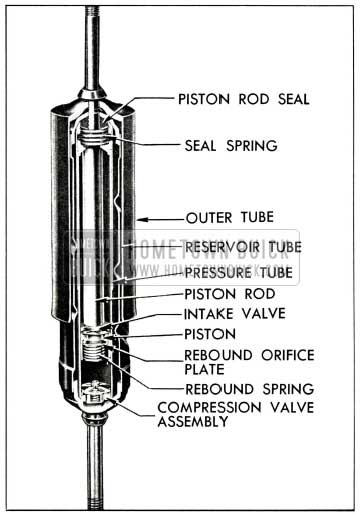
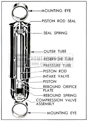
1958 Buick Front Shock Absorber-Sectional View
Each 1958 Buick front shock absorber is vertically mounted just rearward of the front spring. The upper stem is attached to a frame bracket and the lower stem to an extension of the spring seat. Both upper and lower stems are mounted with grommets and grommet retainers held in place by a nut.
Each 1958 Buick rear shock absorber is mounted on an angle with the upper end in toward the center of the car. The upper end is attached to a bracket bolted on the frame through rubber bushings. The lower end is attached to a bracket welded on the rear axle housing through rubber bushings. See figure 7-5.
1958 Buick Rear Shock Absorber-Sectional View
Right and left front shock absorbers are identical and interchangeable. Right and left rear shock absorbers are also identical and interchangeable. Front and rear shock absorbers are of the same general type, but are not interchangeable.
For any particular model, the front shock absorbers are interchangeable between air spring and coil spring equipped cars.
CAUTION: Rear shock absorbers on jobs equipped with Air-Poise Suspension have an extended length which is approximately 1″ shorter than the extended length of standard shock absorbers. Standard rear shock absorbers must not be used on Air-Poise Suspension jobs as serious damage to the air springs may result.
1958 Buick Shock Absorber Construction and Operation
The 1958 Buick shock absorber consists of three concentric tubes, a piston and rod, and valves for controlling hydraulic resistance. The pressure (inner) tube provides a cylinder in which the piston and rod operate. The upper end is sealed by a piston rod seal, and the lower end is closed by the compression valve assembly. This tube is completely filled with fluid at all times. The reservoir (middle) tube provides space for reserve fluid and for overflow from the pressure tube during operation. The outer tube telescopes over the reservoir tube to provide a dust shield.
The piston, piston rod and outer tube are attached to the car frame, while the pressure and reservoir tubes are attached as a unit to the 1958 Buick chassis suspension through the mounting eye. As the wheel moves up and down with respect to the frame the 1958 Buick chassis spring compresses or expands, and the shock absorber is telescoped or extended. This action forces the fluid to move between the pressure and reservoir tubes through small restricting orifices in the valves. The relative slowness of fluid movement imposes restraint on the telescoping or extension of the shock absorber, thus providing the required dampening effect on spring action.
- Compression Stroke Operation. When the 1958 Buick chassis spring is being compressed the shock absorber is telescoped, causing the piston to move down in the pressure tube, forcing fluid through holes in the piston. The pressure lifts the intake valve plate, allowing fluid in lower chamber to pass into the upper chamber. As the piston rod moves downward into the pressure tube it occupies space previously filled with fluid and this displaced fluid is forced out of the lower chamber into the reservoir through the restricting orifice in the compression valve. On fast or extreme movements when the fluid flow exceeds the capacity of the orifice, the spring loaded relief valve in the compression valve assembly is forced open to permit more rapid escape of fluid. The amount of compression control is governed entirely by the volume of fluid displaced by the piston rod, and the resistance to chassis spring travel is governed by the area of the orifice and the strength of the compression relief valve spring.
- Rebound Stroke Operation. When the 1958 Buick chassis spring expands, or rebounds, the shock absorber is extended and its resistance is instantly effective. As the piston is pulled upward the intake valve plate seats and fluid in the upper chamber is forced through slots in the plate and holes in the piston to build up pressure against the rebound orifice plate. As the pressure increases, the rebound spring is compressed and the orifice plate leaves its seat to permit fluid to pass into the lower chamber. As the piston rod moves upward out of the pressure tube the space previously occupied by the rod is filled with fluid drawn into the lower chamber from the reservoir. A separate intake valve in the compression valve assembly opens to permit return of this fluid.
Leave A Comment
You must be logged in to post a comment.