SECTION 3-F 1958 BUICK CARTER 4-BARREL CARBURETOR
3-20 DESCRIPTION AND OPERATION OF 1958 BUICK CARTER 4-BARREL CARBURETOR
General Description
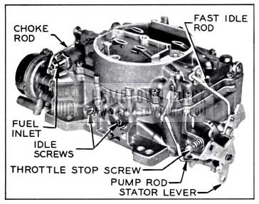
The Carter Model AFB carburetor used on the Series 50-60-70-700 engine is a 4-barrel downdraft type which provides the advantages of a compound installation of two 2-barrel carburetors in one compact unit. See figure 3-40.
1958 Buick Carter AFB Carburetor Assembly
To aid description and the proper identification of parts the 1958 Buick Carter 4-barrel Carburetor is considered to be divided into a primary section and a secondary section.
The primary section covers the 2-barrelled forward half of the 1958 Buick Carter 4-barrel Carburetor assembly. This section is essentially a complete 2-barrel carburetor containing a low speed system, high speed system, power system, and accelerating system. This section also includes a 1958 Buick Carter 4-barrel Carburetor starter switch for starting the engine, and the climatic control (automatic choke) mechanism.
The secondary section covers the 2-barrelled rearward half of the 1958 Buick Carter 4-barrel Carburetor assembly. This section is essentially a supplementary 2-barrel carburetor which cuts in to assist the primary section when a pre-determined car speed or engine load is reached. This section contains its own high speed system. It has a separate set of throttle valves and a set of auxiliary valves which are located in the barrels above the throttle valves.
The primary throttle valves are operated by the accelerator pedal and the connecting throttle linkage. The secondary throttle valves are operated by the primary throttle valve shaft through delayed action linkage which permits a pre-determined opening of the primary valves before the secondary valves start to open. Action of the linkage then causes both sets of throttle valves to reach the wide open position at the same time.
The starter switch, which is operated by the primary throttle valve shaft, is fully described in paragraph 10-30. The other systems of the 1958 Buick Carter 4-barrel Carburetor are described in the following subparagraphs.
Operation of Float Systems
The purpose of the float system is to maintain an adequate supply of fuel at the proper level in the bowl for use by the low-speed, high speed, pump and choke circuits.
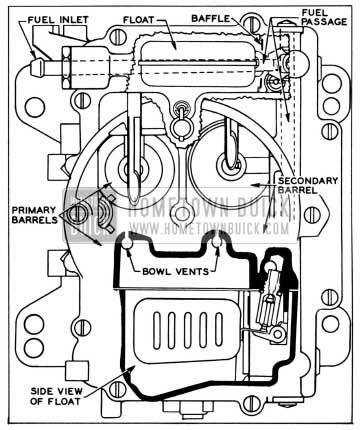
There are two separate float circuits. Each float circuit supplies fuel to a primary low speed circuit and a primary and secondary high-speed circuit. See figure 3-41.
1958 Buick Float Circuit
Setting the floats to specifications assures an adequate supply of fuel in the bowls for all operating conditions. Special consideration should be given to be sure the floats do not bind in their hinge pin brackets or drag against inner walls of bowl.
The intake needle seats are installed at an angle to provide the best possible seating action of the intake needles.
Intake needles and seats are carefully matched during manufacture. Do not use the left needle in the right seat or vice versa. To avoid unnecessary bending, both floats should be reinstalled in their original positions and then adjusted.
The bowls are vented to the inside of the air horn and also to atmosphere. A connecting vent passage in the air horn effects a balance of the air pressure between the two bowls. Bowl vents are calibrated to provide proper air pressure above the fuel at all times.
Operation of Low Speed Systems
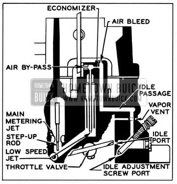
Fuel for idle and early part throttle operation is metered through the low speed system. The low speed system is located on the primary side only. See figure 3-42.
1958 Buick Low Speed Circuit
Gasoline enters the idle wells through the main metering jets. The low speed jets measure the amount of fuel for idle and early part throttle operation. The air by-pass passages, economizers and idle air bleeds are carefully calibrated and serve to break up the liquid fuel and mix it with air as it moves through the passages to the idle ports and idle adjustment screw ports. Turning the idle adjustment screws toward their seats reduces the quantity of fuel mixture supplied by the idle circuit.
The idle ports are slot shaped. As the throttle valves are opened, more of the idle ports are uncovered allowing a greater quantity of the gasoline and air mixture to enter the 1958 Buick Carter 4-barrel Carburetor bores. The secondary throttle valves remain seated at idle.
The low speed jets, air bleed, economizer and by-pass bushings are pressed in place in the venturi assemblies. Do not remove in servicing. If replacement is necessary, use a new venturi assembly. To insure proper alignment of the low speed mixture passage, each primary venturi assembly is designed so it can be installed on one side only.
To assist in quick hot engine starting, fuel vapor accumulated in the primary and secondary bores is vented to atmosphere through vent passages above throttle valves.
To combat engine stalling during warm-up on cool humid days, caused by “carburetor icing”, exhaust gases are directed against a steel baffle plate that contacts the 1958 Buick Carter 4-barrel Carburetor mounting flange. The heat transferred helps eliminate ice formation at the throttle valve edges and idle ports.
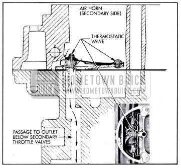
To compensate for loss of engine RPM while idling under very hot operating conditions, a thermostatic valve assembly is installed in the web between the right and left secondary venturi. When the temperature rises beyond a certain point, the calibrated thermostatic spring opens the valve. This allows additional air to flow through a special passage to an outlet below the secondary throttle valves. The thermostatic valve cannot be adjusted or repaired; therefore, a faulty valve must be replaced. See figure 3-43.
1958 Buick Thermostatic Valve Assembly
Operation of High Speed Systems
Fuel for all except early part throttle and for all full throttle operation is supplied through the high speed system. See figure 3-44.
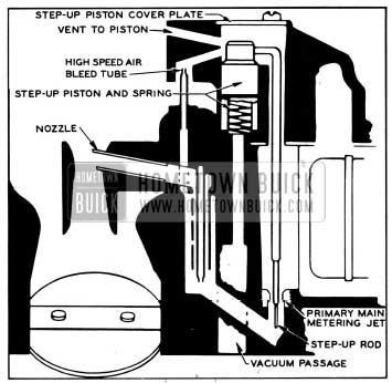
1958 Buick Primary High Speed Circuit
The position of the step-up rod in the primary main metering jet controls the amount of fuel admitted to the nozzles. The position of the step-up rod is controlled by manifold vacuum applied to the vacuum piston.
During normal part throttle operation, manifold vacuum pulls the step-up piston and rod assembly down, holding the larger diameter of the step-up rod in the primary main metering jet. This is true when the vacuum under the piston is strong enough to overcome the tension of the step-up piston spring. Fuel is then metered around the larger diameter of the step-up rod in the jet.
Under any operating condition, when the tension of the spring overcomes the pull of vacuum under the piston, the step-up rod will move up so its smaller diameter or power step is in the jet. This allows additional fuel to be metered through the jet. The step-up rod does not require adjustment.
Fuel for the high-speed circuit of the secondary is metered at the main metering jets (no step-up rods used). See figure 3-45.
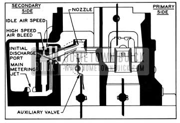
1958 Buick Secondary High Speed Circuit
Initial discharge ports are incorporated to supplement starting of the fuel flow in the secondary high-speed circuit. These ports are located next to the venturi struts. When the auxiliary valves start to open, the vacuum on the initial discharge ports pulls fuel into pickup tubes below the fuel level. Air bleeds serve to break-up the liquid fuel and mix it with air as it moves through the passages to the initial discharge ports where it is discharged into the air stream. As the auxiliary valves continue to open, and the secondary nozzles start delivering fuel, less fuel flows from the initial discharge ports.
The main vent tubes on primary and secondary sides mix air drawn through the high speed air bleed with the fuel before it passes out of the nozzles.
A clogged air bleed or main vent tube may cause excessively rich mixtures. The high speed bleed and main vent tubes are permanently installed. If replacement is necessary, use a new venturi assembly.
The high speed bleeds also act as anti-percolator vents when a hot engine is stopped or at idling speed. This will help vent fuel vapor pressure in the high speed and idle well before it is sufficient to push fuel out of the nozzles and into the intake manifold.
Engines operated at part throttle on level road use a mixture of maximum leanness. The mixture for greatest power and acceleration is somewhat richer, and is furnished by the power and accelerating systems described later.
The high speed systems in the primary section control the flow of fuel during the intermediate or part throttle range of operation and up to approximately 85 MPH. The secondary throttle valves remain closed until the primary valves have opened approximately 40-45 degrees, after which they are opened proportionately so that all valves reach the wide open position at the same time. While the secondary valves are closed, the auxiliary valves located above them are held closed by the weights on the auxiliary valve shaft lever (fig. 3-45); therefore there is not sufficient air flow through the barrels to operate the high speed systems in the secondary section.
When the secondary throttle valves are open and the engine speed is at least 1400-1600 RPM, the •resulting air flow through the secondary barrels starts to open the auxiliary valves because their supporting shaft is located off-center in the barrels. When the auxiliary valves are open the high speed systems in the secondary section also supply fuel to the engine.
Operation of the Power System
For maximum power or high speed operation above approximately 85 MPH, a richer mixture is required than that necessary for normal throttle opening. The richer mixture is supplied through the high speed systems in the primary section through vacuum control of the step-up rods.
Each power circuit consists of a vacuum piston located in a cylinder connected to manifold vacuum and a spring which tends to push the piston upward against manifold vacuum. See figure 3-46.
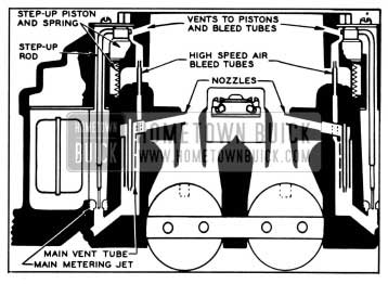
1958 Buick Power Circuit
Under part throttle operation, manifold vacuum is sufficient to hold the piston and rod down against the tension of the spring, so that the large diameter of the rod is in the metering jet for economy. When the throttle valve is opened to a point where additional fuel is required for satisfactory operation, manifold vacuum decreases sufficiently so that the piston spring moves the piston and rod upward to the small rod diameter to give the required richer mixture for power. As soon as the demand is passed, manifold vacuum again moves the piston and rod down.
Operation of Accelerating System
The accelerating pump circuit, located in the primary side, provides a measured amount of fuel necessary to insure smooth engine operation on acceleration at lower car speeds.
When the throttle is closed, the pump plunger moves upward in its cylinder and fuel is drawn into the pump cylinder through the intake check. The discharge check is seated at this time to prevent air being drawn into the cylinder. When the throttle is opened, the pump plunger moves downward forcing fuel out through the discharge passage, past the discharge check, and out of the pump jets. When the plunger moves downward, the intake check is closed, preventing fuel from being forced back into the bowl. See figure 3-47.
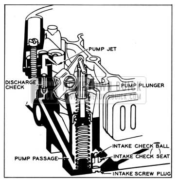
1958 Buick Pump Circuit
At higher car speeds, pump discharge is no longer necessary to insure smooth acceleration. When the throttle valves are opened a predetermined amount, the pump plunger bottoms in the cylinder eliminating further pump discharge.
Be sure the pump plunger leather is in good condition and the intake and discharge checks and pump jet are free of lint, gum or other foreign matter. To facilitate service, the intake check ball and seat may be inspected and replaced by removing the screw-in plug in the face of the flange without complete disassembly of the 1958 Buick Carter 4-barrel Carburetor.
Operation of Climatic Control
The choke circuit, located in the primary side, provides the correct mixture necessary for quick cold engine starting and during engine warm-up.
When the engine is cold, tension of the thermostatic coil holds the choke valve closed. When the engine is started, air velocity against the offset choke valve causes the valve to open slightly against the thermostatic coil tension. Intake manifold vacuum applied to the choke piston also tends to pull the choke valve open. The choke valve assumes a position, where tension of the thermostatic coil is balanced, by the pull of vacuum on the piston, and force of air velocity on the offset valve.
When the engine starts, slots located in the sides of the choke piston cylinder are uncovered, allowing intake manifold vacuum to draw warm air through the climatic control housing. This air is heated in a tube running through the exhaust manifold stove. The flow of warm air heats the thermostatic coil and causes it to lose some of its tension. The thermostatic coil loses its tension gradually, until the choke valve reaches full-open position.
If the engine is accelerated during the warmup period, the corresponding drop in manifold vacuum allows the thermostatic coil to momentarily partially close the choke, providing a richer mixture.
During the warm-up period, it is necessary to provide a fast idle speed to prevent engine stalling. This is accomplished by a fast idle cam connected to the choke linkage. The fast idle adjusting screw on the throttle lever contacts the fast idle cam and prevents the throttle valves from returning to a normal warm engine idle position, while the choke is in operation. See figure 3-48.
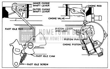
1958 Buick Choke Linkage
If during the starting period the engine becomes flooded, the choke valve may be opened manually to clean out excessive fuel in the intake manifold. This is accomplished by depressing the accelerator pedal to the floor mat. The unloader projection on the throttle lever contacts the fast idle cam which rotates and partially opens the choke valve.
The secondary section does not have a choke valve. In order to prevent air entering the 1958 Buick Carter 4-barrel Carburetor through the secondary side during the engine warm-up period, it is necessary to lock the secondary throttle valves in the closed position. This is accomplished by engagement of a lock-out arm with a locking tang on the valve shaft lever. See figure 3-40.
With the choke valve in wide open position the lock-out arm rests in a lowered position, clear of the secondary valve shaft lever. As the choke valve closes it rotates the fast idle cam trip lever, allowing the lock-out arm to raise. As soon as the choke valve is closed a few degrees from wide open position, the notch in the lock-out arm lies in the line of travel of the locking tang on the valve shaft lever, thereby preventing the shaft and valves from turning.
3-21 DISASSEMBLY, CLEANING, INSPECTION OF 1958 BUICK CARTER 4-BARREL CARBURETOR
Disassembly of 1958 Buick Carter 4-barrel Carburetor
- Remove pin spring from upper end of choke rod and disconnect rod from choke shaft lever. Reinstall pin spring on choke rod for safe keeping.
- Remove retainer and spring from upper end of pump rod and disconnect rod from pump arm. Reinstall spring and retainer on pump rod.
- Remove screws holding two step-up piston cover plates to air horn. Remove cover plates and remove each step-up piston, rod, and rod retainer spring as an assembly. Then remove two step-up piston springs. See figure 3-49.
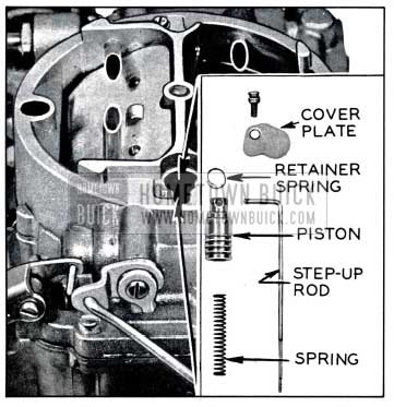
1958 Buick Step-Up Rod and Related Parts
For normal cleaning and inspection, it is not necessary to remove primary or secondary throttle valves and their connecting linkage. However, if throttle linkage is worn or damaged, service replacement parts are available.
3-22 ASSEMBLY AND ADJUSTMENT OF 1958 BUICK CARTER 4-BARREL CARBURETOR
During assembly of 1958 Buick Carter 4-barrel Carburetor, use all new gaskets and any additional new parts found to be necessary during inspection. Calibrated parts must be as specified for carburetor CODE number which is stamped in edge of mounting flange at rear center.
- With 1958 Buick Carter 4-barrel Carburetor main body inverted, install pump intake check ball, ball seat, and screw plug with a new gasket.
- Place main body in upright position on bench or mounting fixture. Install primary and secondary metering jets and tighten securely. NOTE: The primary jets are the two having the larger orifices and are installed in the holes nearest the center of the main body below step up rod holes in air horn.
- Install pump discharge check needle point down. Install pump jet housing and gasket.
- Install auxiliary valve assembly with screw heads down. Then install secondary and primary venturi assemblies, using new gaskets. NOTE: If a primary venturi assembly does not fit in place flush with top of main body, it belongs on other side.
- Install idle mixture adjustment screws. Seat lightly and back out 1% turn, which will provide an average initial adjustment. Install starter switch ball, plunger (with groove up), guide block assembly, return spring, terminal cap and screws in main body. See figure 10-26. Lubricate terminal cap as described in paragraph 10-30 and check switch timing if there is any indication that switch is not functioning properly. Install new starter switch strainer if old strainer was removed.
- Install choke piston housing shaft, lever and rod assembly in piston housing with lever and rod pointing away from heat pipe connector. Install small round rubber gasket in housing recess, then install piston housing on main body using three black screws. Install choke piston, pin link, and lever assembly in piston housing. Install piston lever on flats of shaft in such a way that inner and outer levers are pointing in same general direction. Then install special washer and screw.
- Place pump plunger assembly in position in air horn and install pump link. Install pin spring in upper end of link. Invert air horn and install new air horn gasket.
- Install float needle seats and gaskets. Install float needles, floats, and lever pins, making sure they are installed in original locations.
- Align Float. Sight down side of float to determine if side is parallel with outer edge of air horn. If adjustment is necessary, bend float lever by applying pressure to end of float with fingers while supporting float lever with thumb. See figure 3-50.
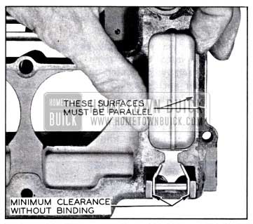
1958 Buick Float Alignment
Remove any excess clearance between arms of float lever and lugs on air horn by bending float lever arms. Arms should also be parallel to inner surfaces of lugs. After aligning, each float must operate freely.
- Adjust Float Level. With air horn inverted and air horn gasket in place, check clearance between each float (at outer end) and air horn gasket using Float Gauge T109-106 (7/32″) or a 7/32″ drill. See figure 3-51. To adjust; bend float lever. After any adjustment, recheck float alignment.
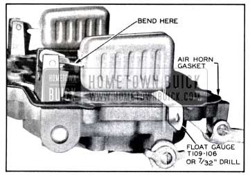
1958 Buick Checking Carburetor Float Level
1958 Buick Checking Float Drop
1958 Buick Choke Piston Adjustment
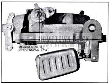
1958 Buick Pump Adjustment
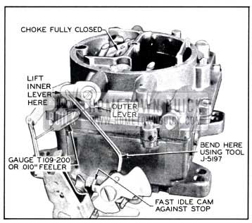
1958 Buick Fast Idle Rod Adjustment
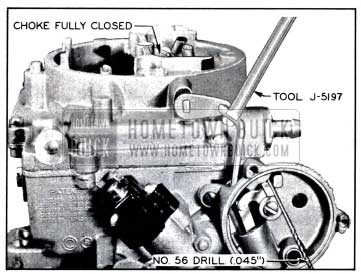
1958 Buick Unloader Adjustment

1958 Buick Closing Shoe Adjustment
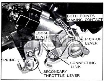
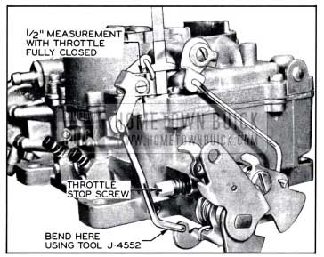
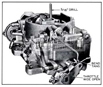
1958 Buick Secondary Throttle Opening Adjustment
The primary and secondary throttle valve must come to the wide open position simultaneously. If the secondary throttle valve opening is not synchronized with that of the primary, bend the connecting link. See figure 3-58.
Adjust Secondary Throttle Lock-Out. Open primary throttle valves slightly and manually open and close choke valve. Tang on secondary throttle lever should freely engage in notch of lock-out dog while barely missing edge of notch. If necessary to adjust, bend tang on secondary throttle lever using Tool J-6058-A. See figure 3-59.
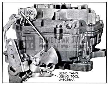
1958 Buick Secondary Throttle Lock-Out Adjustment
- Install 1958 Buick Carter 4-barrel Carburetor on car. Make final idle speed and mixture adjustments on car in normal manner. See paragraph 3-8.
- Adjust Fast Idle. Make adjustment on car with engine at normal operating temperature as follows:
- Push fast idle cam to position where fast idle screw contacts high step of cam.
- Adjust fast idle screw until engine is running 1500 RPM.
Leave A Comment
You must be logged in to post a comment.