SECTION 6-B 1956 BUICK REAR AXLE SERVICE PROCEDURES
6-4 REMOVAL AND INSTALLATION OF 1956 BUICK REAR AXLE ASSEMBLY
It is not necessary to remove the 1956 Buick rear axle assembly for repair or replacement of a strut rod, an axle shaft, a wheel bearing, or a wheel bearing seal; however, the 1956 Buick rear axle assembly should be removed for any other repairs.
Removal of 1956 Buick Rear Axle Assembly
- Place car stands solidly under frame so that rear end of car is high enough to permit working underneath and place a floor jack under center of axle housing so it just supports weight of 1956 Buick rear axle assembly.
- Disconnect radius rod at axle end.
- Disconnect lower ends of rear springs.
- Disconnect lower ends of rear shock absorbers.
- Disconnect parking brake cable at rear cable sheave and at bracket on torque tube. Disconnect brake hose from pipe at frame X member and remove yoke. Cover hose and brake pipe openings to prevent entrance of dirt.
- Loosen torque ball retainer bolts so ball is free. Remove two opposite torque tube flange bolts, replacing them with two 3″ guide pins. Remove other flange bolts. See Figure 6-2.
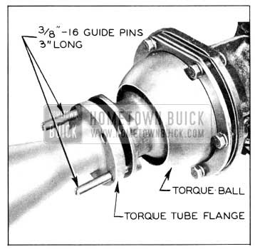
1956 Buick Removing Torque Tube from Torque Ball
- Roll 1956 Buick rear axle assembly out from under car.
Installation of 1956 Buick Rear Axle Assembly
- Check torque ball for evidence of oil leaking and for wear of universal joint bushing. If torque ball needs repair or replacement, see paragraph 4-12.
- Check propeller shaft seal for oil leaks or damage. Install a new seal if necessary. Use a new torque tube front flange gasket.
- Rest car solidly on stands placed under frame, with rear end of car high enough to permit working underneath. Roll 1956 Buick rear axle assembly under car.
- Carefully move axle assembly into place, guiding propeller shaft and torque tube into proper alignment with torque ball using two 3″ guide pins to avoid damage to propeller shaft seal. Rotate rear wheel to line-up propeller shaft and universal joint splines.
- Connect torque tube to torque ball, tightening bolts to 30-35 ft. lbs. Do not tighten torque ball retainer bolt s at this time.
- Connect rear springs to 1956 Buick rear axle assembly. Connect shock absorber lower ends loosely.
- Connect brake hose to brake pipe at frame X member and lock in place with yoke. Connect parking brake cable through bracket on torque tube and to brake cable sheave. Bleed rear wheel cylinders and adjust parking brake as described in paragraphs 9-7 and 9-9.
- Connect radius rod loosely to 1956 Buick rear axle.
- Lower car on wheel stands. Then tighten torque ball retainer bolts, shock absorber lower ends, and radius rod lower end.
NOTE: Normal weight must be on rear wheels when tightening these part s so that rubber bushings will be clamped in neutral position.
- Lower car to floor. Fill axle housing to filler plug hole using approved gear lubricant.
6-5 REPLACEMENT OF 1956 BUICK REAR AXLE STRUT ROD
The rear ends of the strut rods are attached to the axle housing by nuts. The front ends of both strut rods are bolted through rubber compression bushings to a bracket welded on the torque tube. Strut rods may be replaced without removing 1956 Buick rear axle assembly.
CAUTION: When a strut rod is damaged, there is a good possibility that the 1956 Buick rear axle housing is sprung.
6-6 REPLACEMENT OF 1956 BUICK AXLE SHAFT, WHEEL BEARING, OR OIL SEAL
Removal of 1956 Buick Axle Shaft Assembly
- Place car stands solidly under 1956 Buick rear axle housing so that wheels are clear of floor.
- Remove rear wheel and brake drum.
- Remove nuts holding wheel bearing retainer plate to brake backing plate, leaving bolts in place to support backing plate.
- Pull out axle assembly using Puller J-6176 with a slide hammer. Be careful not to disturb brake backing plate. See Figure 6-3.
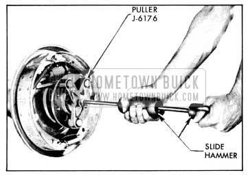
1956 Buick Removing Rear Axle Shaft
- Replace two opposite nuts finger tight to hold brake backing plate in position.
Replacement of 1956 Buick Wheel Bearing or Oil Seal
The oil seal is located on the outer side of the bearing between the inner and outer races of the wheel bearing.
- Nick the wheel bearing retaining ring. NOTE: The ring need not be completely split, but nicked deep enough in 3 or 4 places to spread it. Retaining ring will then slip off with light pressure. See Figure 6-4.
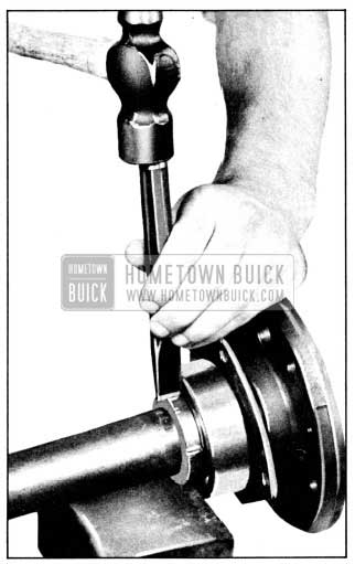
1956 Buick Removing Rear Wheel Bearing Retaining Ring
- Press the wheel bearing off, using Plate J-6191 either in a press or in a set-up using Ram and Yoke Assembly J-6180 and Adapter J-6258 as shown in figure 6-5.
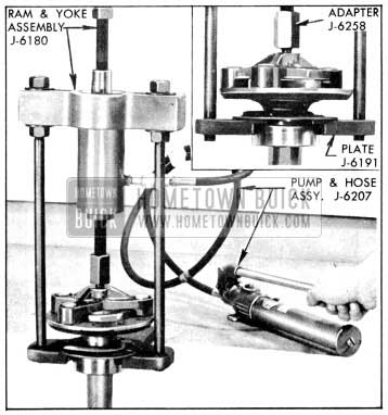
1956 Buick Removing Rear Wheel Bearing
- If seal only is defective, pry old seal from bearing and install new seal using Guide J-6213. Push seal in carefully with fingers until lip is over bearing inner race; then remove installing guide and drive seal in flush with a flat wood block. See figure 6-6.
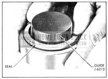
1956 Buick Installing Rear Wheel Bearing Oil Seal
- Press bearing and seal assembly against shoulder on axle shaft using Installer J-6257 either in a press or in a set-up using Ram and Yoke Assembly J-6180 and Holder J-6274 as shown in figure 6-7.
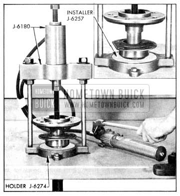
1956 Buick Installing Rear Wheel Bearing or Retaining Ring
NOTE: Bearing retainer plate must be on axle shaft before bearing is installed.
Then press retaining ring against bearing with chamfer toward bearing.
Installation of 1956 Buick Axle Shaft
1956 Buick rear axle shafts are not interchangeable between sides; the right shaft is longer than the left and has an extra set of splines for driving the oil pump.
- Install new gasket at bearing shoulder in housing. See Figure 6-8.
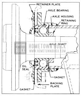
1956 Buick Axle Shaft and Bearing Assembly
- If wheel bearing or seal are only new parts used, replace old wheel bearing retainer gaskets with same number and thickness of new gaskets.
- I f new rear axle housing or new brake backing plate are used, install axle shaft and bearing assembly without retainer gaskets. Using slide hammer and Puller J-6176, drive axle shaft and bearing in place until bearing is fully seated. To hold the retainer plate snug against the face of the bearing, install the four (4) nuts and tighten finger tight.
With the brake backing plate pushed tight against the housing flange, measure clearance between retainer and backing plate with feelers. Use two feeler gauges at the same time at opposite sides of the retainer plate to prevent any error caused by tipping of the backing plate. Average the two readings so obtained and select the number of new gaskets as required to give .005″ to .020″ less thickness than the average of the two feeler measurements. This adjustment must be made carefully to be sure that wheel bearing inner gasket is held tightly against its shoulder by the wheel bearing. A loose fit here will allow gear oil to leak around the bearing outer race.
- Replace nuts holding wheel bearing retainer plate to brake backing plate and tighten to 65-75 ft. lbs. Then check with a .001″ feeler gauge under retainer plate between two lower bolts. If a gap exists between the two lower bolts, remove plate and apply non-hardening Permatex on both sides of gasket to prevent any possible leak from draining into the brake.
- Replace brake drum and rear wheel.
- Remove car from stands; then check to be sure that gear oil level is at filler plug opening.
6-7 REMOVAL OF 1956 BUICK TORQUE TUBE, PROPELLER SHAFT, AND CARRIER ASSEMBLY
Removal of 1956 Buick Torque Tube and Propeller Shaft
- Remove 1956 Buick rear axle assembly from car (par. 6-4) 0
- Place axle assembly on suitable stands. See figure 6-9.
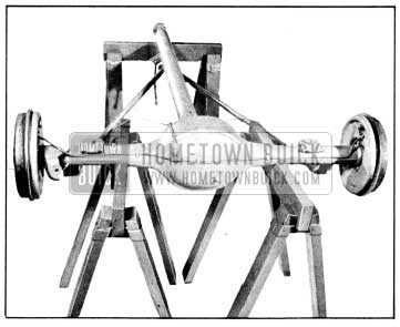
1956 Buick Placing Rear Axle Assembly on Stands
- Disconnect torque tube brake line from tee fitting located on 1956 Buick rear axle housing.
- Disconnect strut rods from torque tube bracket. Fasten the two strut rod ends to each other loosely, keeping all parts in their original positions.
- Remove torque tube to carrier bolts. Slide torque tube and propeller shaft from carrier.
- Move stand so it will support the strut rods midway.
CAUTION: The strut rods are easily bent while disconnected from the torque tube.
Removal of Carrier Assembly
- Remove 1956 Buick rear axle assembly from car (par. 6-4).
- Place axle assembly on suitable stands and remove torque tube and propeller shaft as described in par. 6-7, (a).
- Remove brake line from 1956 Buick rear axle housing to avoid damaging it later.
- Remove both axle shaft assemblies (par. 6-6).
- Rotate axle housing so carrier is upward.
- Remove carrier to axle housing nuts and lift carrier from housing using Sling J-6247 and a chain hoist, if available. See Figure 6-10.
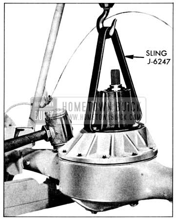
1956 Buick Removing Carrier Assembly from Rear Axle Housing
6-8 CLEANING AND INSPECTION OF 1956 BUICK REAR AXLE PARTS
Cleaning 1956 Buick Rear Axle Parts
Hypoid lubricant combines readily with water and even a small amount of water has a deteriorating effect on the lubricant. For this reason steam or water should not be used for cleaning 1956 Buick rear axle parts.
Gasoline, kerosene, or other solvents are satisfactory for cleaning parts when removed from 1956 Buick rear axle housing, if parts are thoroughly dried before installation. No solvent should be used in an assembled 1956 Buick rear axle, however, because if all traces of the cleaner are not removed, the fresh lubricant will be contaminated. If the 1956 Buick rear axle needs cleaning, it must be removed from the car and disassembled.
Wash all disassembled parts in clean solvent and wipe with clean, dry cloths. Vapor degreasers must not be used on painted parts, seals or bearings. Finish drying with clean dry air blast. Do not spin bearings.
Inspection of 1956 Buick Rear Axle Parts
- Thoroughly inspect rear wheel bearing for rust, binding, or excessive looseness as shown under Bearing Service (par. 1-10).
- 1956 Buick Propeller Shaft. Check for wear of splines. Splines must be a snug slip fit when assembled. These splines are designed to give slight angular freedom but must not have excessive backlash.
- 1956 Buick Rear Axle Housing and Torque Tube. A sprung housing or torque tube should be replaced; straightening is not recommended. These parts must never be heated with a torch for straightening as this may produce distortion of machined bores or soft spots in the metal in which fatigue and breakage may develop in service. Inspect carefully for cracks, especially at welds.
6-9 INSTALLATION OF 1956 BUICK CARRIER ASSEMBLY, PROPELLER SHAFT AND TORQUE TUBE
Installation of 1956 Buick Carrier Assembly
Before installing the carrier assembly, the carrier and axle housing mounting surfaces must be clean and free of any old gasket material. Also, make sure these surfaces are free of any burrs or nicks.
- Rotate axle housing so that carrier mounting surface is upward and install a new carrier gasket.
- Install carrier assembly in axle housing using Sling J-6247 as shown in figure 6-10. Install nuts and tighten them evenly and alternately to 50-60 ft. lbs.
- Install brake line on 1956 Buick rear axle housing.
- Install both axle shaft assemblies (par. 6-6).
Checking 1956 Buick Propeller Shaft
The 1956 Buick propeller shaft now used is free to float on the pinion splines. If the 1956 Buick propeller shaft is handled carefully during removal and installation, it will not normally be necessary to perform a dial indicator check for straightness.
However, if there is a noise or vibration at high speeds which might be caused by a bent shaft (par. 6-3, C), or if there is any possibility that the shaft has been damaged due to rough handling or collision, the propeller shaft should be checked for straightness as follows:
- Support propeller shaft on V-blocks placed under the seal sleeve at “A” and under the coupling at “B.” See figure 6-11.
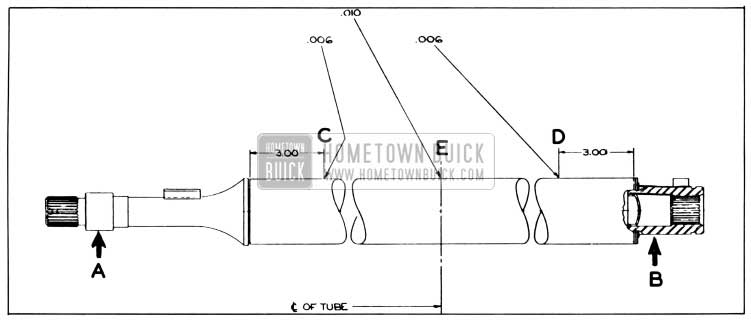
1956 Buick Propeller Shaft Run-Out Specifications
- Mount a dial indicator on a suitable base and check run-out at “C” and “D” located 3″ from each end of tube. Then check run-out at “E” located near center of tube.
- Run-out at “C” and “D” must not exceed .006″; run-out at “E” must not exceed .010″.
However, care must be taken not to include indicator variation due to the shape of the tube in run-out readings. Indicator fluctuation due to ridges, flat spots, or an oval tube must be ignored.
NOTE: If the 1956 Buick propeller shaft is turned rapidly, it is easier to ignore any surface imperfections and to properly locate the high center of a bent propeller shaft.
- If run-out exceeds specifications due to a bent propeller shaft, it is probably more economical to replace the shaft than to attempt straightening it. However, if it is decided to straighten the shaft, mark points of greatest run-out along the length of the tube. By studying these high center marks, the general type and extent of the bend may be readily seen and the straightening procedure planned accordingly.
Straightening 1956 Buick Propeller Shaft
In order to straighten a 1956 Buick propeller shaft, the following tools are necessary: an arbor press, a bending block and two support blocks which are shaped to conform to the tube, and a support which conforms to the seal sleeve shape. This straightening set-up should be near the checking set-up because the shaft must be rechecked after every bend.
The method used in straightening depends on the type of bend. In general, pressure should be applied at the high center of the bend with the shaft supported at both ends of the bend. Then by checking and bending repeatedly, the high center can be brought down until the indicator reading at this point is approximately the same as that at a point 180 degrees opposite. When bending the shaft, use steady pressure and not shock blows to spring the shaft.
Installation of 1956 Buick Propeller Shaft
- Check propeller shaft and pinion splines for excessive wear. Remove any nicks or burrs. Replace propeller shaft seal sleeve if scored or grooved. Inspect propeller shaft rear packing and retainer and replace if worn or damaged.
- Pack rear propeller shaft coupling with heavy wheel bearing grease (Buick Spec. #555) bringing level to inner end of the splines.
- Slide propeller shaft on splines of pinion.
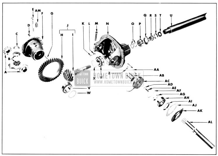
1956 Buick Carrier Assembly Exploded
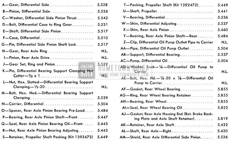
1956 Buick Carrier Assembly Legend
Installation of 1956 Buick Torque Tube
Before installing the 1956 Buick torque tube, flanges on both ends must be free of burrs or nicks. Also, check the torque tube mounting surface on the carrier.
- Slide torque tube over propeller shaft being careful to keep torque tube centered on propeller shaft to avoid side thrust.
CAUTION: Propeller shaft will bend easily if side pressure is put on it.
- Position 1956 Buick torque tube with strut rod bracket downward, being careful not to damage brake line. Install torque tube to carrier bolts and tighten alternately to 50-60 ft. lbs.
NOTE: No gasket is used between the torque tube and carrier.
- Connect brake line at tee on 1956 Buick rear axle housing. Connect strut rods and tighten bolt to 85-100 ft. lbs.
- Install 1956 Buick rear axle assembly in car. (par 6-4).
6-10 DISASSEMBLY OF 1956 BUICK CARRIER ASSEMBLY
Removal and Disassembly of 1956 Buick Ring Gear and Case Assembly
- Place carrier assembly in suitable mounting fixture such as Fixture J-6177. See Figure 6-13.
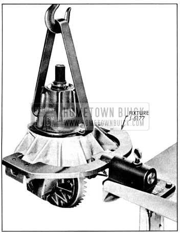
1956 Buick Placing Carrier in Holding Fixture
- It is advisable to check the existing gear lash with a dial indicator as described in paragraph 6-11, f. This will indicate gear or bearing wear or an error in backlash or preload setting. It will also enable used gears to be reinstalled at original lash setting to avoid changing gear tooth contact.
- On 70 Series only, remove oil line and pump.
- Remove differential bearing pedestal clamp bolts and open pedestals by tapping a wedge in each pedestal slot.
CAUTION: Do not use excessive force on wedges as pedestal bores may be permanently distorted.
- Pull differential bearing supports using Puller J-6199 and a slide hammer puller. See Figure 6-14.
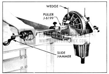
1956 Buick Removing Differential Bearing Supports
- Install Spreader J-6185 shown in figure 6-34. Tighten spreader bolt just enough to free case assembly.
CAUTION: Do not spread pedestals any farther than necessary or they may be permanently sprung.
Lift case straight out until side bearings are half-way clear of pedestals. Then take hold at bearings with both hands to keep them from dropping and lift case assembly out. Keep right and left bearings, shims, and supports in sets so that they may be reinstalled in the same order. Remove spreader tool.
- Mark ring gear and case, so they may be reassembled in same relative position. Remove ring gear.
- Drive differential pinion axle spring pin, pinion axle and pinion shield from case. Mark side gears, pinions, and washers so they may be reinstalled in same sides. Remove side gears, pinions, and spherical washers.
- If a differential bearing is to be replaced, pull bearing outer race from case using Remover J-6269. See figure 6-15.
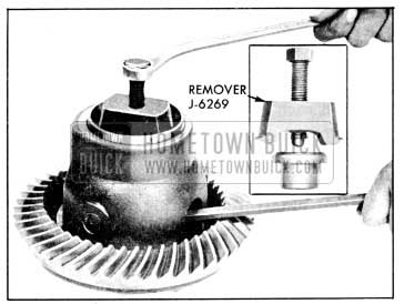
1956 Buick Removing Differential Bearing Outer Race
Removal of 1956 Buick Pinion and Bearings
- Check pinion pre-load as described in paragraph 6-11. This will indicate excessive bearing wear or an error in pre-load setting.
- It is advisable to check the pinion depth setting as described in paragraph 6-11. This will indicate any error in the existing setting and will also enable used parts to be reinstalled at original setting to avoid changing gear tooth contact.
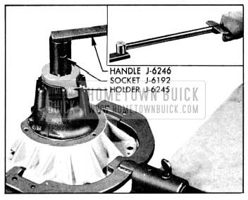
- Cut out and drive up staked section of pinion bearing lock nut with cape chisel, being careful not to damage threads on pinion. Hold pinion nut to carrier with Holder J-6245 and turn pinion clockwise through nut using socket J-6192 and Handle J-6246. See figure 6-16.
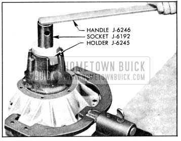
1956 Buick Removing Pinion Nut
- As pinion nut is removed, hold hand under pinion to catch it, as it may fall through. If necessary, tap pinion out with a soft hammer, being careful to guide pinion with hand to avoid damage to bearing outer races.
- If rear pinion bearing is to be replaced or pinion depth setting is to be changed, remove rear bearing from pinion shaft using Remover J-6184 and Holder J-6274 in a press or in a set-up using Ram and Yoke Assembly J-6180 as shown in figure 6-17.
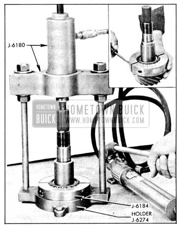
1956 Buick Removing Rear Pinion Bearing
- Pry pinion oil seal from carrier, being careful not to damage front pinion bearing. If front pinion bearing is to be replaced, drive outer race from carrier using Remover J-6198 with Handle J-872-5. See figure 6-18.
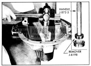
1956 Buick Removing Front Pinion Bearing Outer Race
- If rear pinion bearing is to be replaced, drive outer race from carrier using Remover J-6256 with Handle J-872-5.
NOTE: The remover must be inserted in carrier before the driver handle is screwed into it. See figure 6-19.
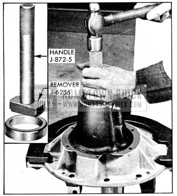
1956 Buick Removing Rear Pinion Bearing Outer Race
6-11 ASSEMBLY OF 1956 BUICK CARRIER ASSEMBLY
Installation of Pinion and Bearings
Before installation of pinion and bearings make certain that interior of carrier housing is absolutely clean and dry. Also make certain that parts to be assembled are clean and that pinion bearing shims are not burred. Bearings and oil seals should be lightly lubricated with rear axle lubricant just before assembly.
- Drive front pinion bearing outer race against shoulder in carrier using Replacer J-6197 with driver handle. See figure 6-20.
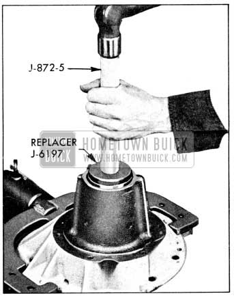
1956 Buick Installing Front Pinion Bearing Outer Race
- Drive rear pinion bearing outer race against shoulder in carrier using Replacer J-6255 with driver handle. See figure 6-21.
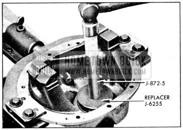
1956 Buick Installing Rear Pinion Bearing Outer Race
- Whenever a new carrier, a new pinion, or a new pinion bearing is to be used, a trial assembly must be made in order to determine correct pinion depth setting and correct pinion bearing pre-load. For a starting pinion depth setting, use a shim with a nominal thickness of .048″. Place this shim against head of pinion and install rear pinion bearing using Replacer J-6377 and older J-6274 in a press or as shown in figure 6-22.

1956 Buick Installing Rear Pinion Bearing
- For a starting pinion bearing pre-load adjustment, use a pair of spacers with a nominal thickness of .435″. Place these spacers on pinion and hold pinion assembly in position in carrier. Install front pinion bearing and pinion nut. Hold nut to carrier with Holder J-6245 and turn pinion counterclockwise into nut, using Socket J-6192 and Handle J-6246. Do not install pinion seal at this time. Torque pinion nut to 80 foot pounds using Torque Wrench J-1313B on outer end of Handle J-6246. See figure 6-23.
1956 Buick Tightening Pinion Nut
- Rotate pinion three or f our times to seat bearings. Turn pinion slowly with an inch pound torque wrench; bearing pre-load should be 10 to 30 inch pounds. See Figure 6-24.

1956 Buick Checking Pinion Bearing Pre-Load
If pre-load is under 10 inch pounds, replace spacer with a thinner one ; if pre-load is over 30 inch pounds, remove pinion nut and front bearing and replace pre-load spacer with a thicker one. These spacers are furnished to be used in pairs so that possible thicknesses range from .400″ to .470″ by thousandths. Service spacers are marked with their thickness in thousandths.
If pre-load is over 30 inch pounds, the approximate number of thousandths to be added to spacer thickness may be determined from the chart in Figure 6-25.
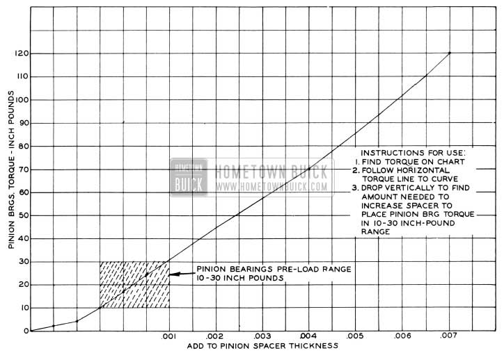
1956 Buick Chart for Correcting Excess Pinion Pre-Load
Pinion Setting Marks and Setting Gauges
All Buick ring and pinion gear sets are selectively matched for best operating position and proper tooth contact. After matching, a serial number is etched on one tooth of pinion and on rear face of gear to aid in keeping matched parts together. See Figure 6-26. Parts having different serial numbers must never be used together.
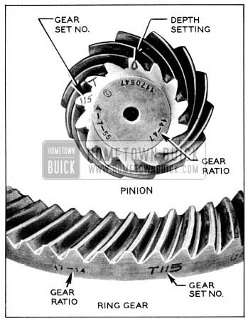
1956 Buick Ring and Pinion Gear Set Markings
Ring and pinion gear sets are matched in a special test machine which permits adjustment of pinion depth in ring gear until a point is reached where best operation and proper tooth contact under load is obtained. At this point, the setting of the pinion with reference to the centerline of the ring gear is indicated by the machine. This setting may vary slightly from the design or “nominal” setting du e to allowable variation in machining the parts.
This variation in thousandths of an inch over or under the “nominal” setting is etched on the small end of a pinion tooth. See figure 6-26.
When a pinion is marked “+” (plus) it means that the rear face of the pinion when pressed in the carrier must be at the “nominal” distance from the centerline of the side bearing pedestals plus the amount indicated on the pinion tooth. When a pinion is marked “-” (minus) it means that it must be located at the “nominal” distance minus the amount indicated on the pinion tooth.
The dial indicator type Pinion Setting Gauge J-5647 is used with adapters to provide a fast and accurate method of checking pinion location; it gives a direct reading on a dial indicator that does not require computation or reference tables. See figure 6-27.
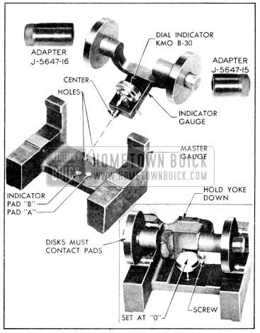
1956 Buick Pinion Setting Gauge J-5647 and Adapters
Before checking the pinion setting, pinion bearing pre-load must be right because incorrect pre-load will cause a false pinion depth reading.
Checking Pinion Setting
Pinion Setting Gauge J-5647 consists of a “master gauge” and an “indicator gauge” upon which Dial Indicator KM0-30-B is mounted. Adapters J-5647-17 are not used when “zeroing the gauge,” but are used in place of the discs when checking the pinion setting. See figure 6-27.
- Make certain that the gauge parts are clean, particularly the center and discs of indicator gauge, the centering holes, indicator pads, disc pads on the master gauge, and the adapter holes and outer surfaces.
- Install the discs on the “indicator gauge” and install the small contact button on the stem of Dial Indicator KM0-30-B. Mount the dial indicator on the indicator gauge. See figure 6-27.
- Place indicator gauge on the master gauge so that the spring loaded center is engaged in the centering hole corresponding to the indicator pad “B,” which is used for any of the following gear ratios stamped on pinion: 43-11 (3.9 to 1), 43-12 ( 3.6 to 1), 47-14 (3.36 to 1), 42-13 (3.2 to 1).
NOTE: Pad “A” is used for certain prior model gear ratios.
- Center the indicator contact button on the specified indicator pad and lock the indicator by tightening the thumb screw.
- Hold yoke down firmly, with both discs contacting the horizontal and vertical pads on master gauge, and set the dial indicator at zero (“0”).
- Make sure that differential bearing support bores are free of burrs and that the center of the pinion is clean.
- Rotate the pinion until the blank tooth between the matching number and the pinion setting mark is slightly counterclockwise of top center (at about 11 o’clock). This tooth is called the gauging tooth (Fig. 6-26) because it is used for locating and gauging during production and should therefore be used for gauging in service.
- Drive a wedge into each pedestal split and spread them just enough so that an Adapter J-5647-17 will slip in. Then place the indicator gauge in the carrier as follows: (see figure 6-28).
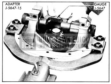
1956 Buick Checking Pinion Setting
- Remove discs from indicator gauge and hold it in position in the carrier with pins centered in the pedestal bores.
- Slide long adapter through pedestal bore farthest from pinion and over gauge pin. Then slide short adapter in place on other side.
- Be sure that gauge center is engaged in pinion center and that adapters are against shoulders of gauge. Then remove pedestal wedges.
- Turn pinion if necessary so that indicator contact button has a good contact with gauging tooth of pinion.
- Press gauge yoke firmly downward toward pinion and read dial indicator noting whether it is plus (+) or minus (-) as indicated by arrows on surface of yoke.
CAUTION: This reading does not indicate the thickness of the shim to be used, but only indicates the variation from the “nominal” setting of the gauging face of this pinion.
- Recheck indicator “zero setting” on master gauge with discs to make sure it was not changed in handling.
- If the old ring and pinion gear set is being reinstalled and it has been in use long enough to establish a wear pattern on teeth, the original pinion setting found before removal should be maintained to avoid changing tooth contact.
- If the ring and pinion set is new, or has not been in use long enough to establish a wear pattern on teeth, the dial indicator reading should be within .001″ of the pinion setting marked on pinion.
- If pinion setting is not as specified, adjust as follows:
Adjustment of Pinion Position
The pinion setting is adjusted by changing the thickness of the shim which is located between the rear pinion bearing inner race and the head of the pinion. These shims are furnished in thicknesses ranging from .040″ to .070″ by thousandths.
- Remove pinion assembly and press off rear pinion bearing using Remover J-6184 and Holder J-6274. (Par. 6-10, b).
- Remove shim from pinion, wipe dry and measure its thickness with a micrometer. Service shims are marked with their thickness in thousandths. Measure shim anyway, however, as any slight error here will necessitate pulling pinion and bearing again.
- Increase or decrease thickness of shim as required to obtain proper pinion setting.
If pinion is marked “+ 8”, but gauge reads “+ 6″, decrease thickness of shim by .002”. If gauge reads “+10″, increase thickness of shim by .002”.
If pinion is marked “-8”, but gauge reads “-6″, increase the thickness of shim by .002”. If gauge reads “-10″, decrease thickness of shim by .002”.
CAUTION: Whenever a new pinion is to be installed, its depth setting must be gauged.
Even though the new pinion has the same depth marking, it may require a different thickness shim because the dimension from the gauging face to the bearing shoulder varies in different pinions.
- Change pre-load spacers by same amount that shim thickness was changed. If thickness of shim was decreased .002″, use spacers with .002″ less thickness. If thickness of shim was increased .002″, u se spacers measuring .002″ thicker.
- Reinstall rear pinion bearing on pinion with new thickness shim. (Par. 6-11, a.)
- Lubricate new pinion seal with axle lubricant and install with lip toward bearing, using Installer J-6200. See Figure 6-29.
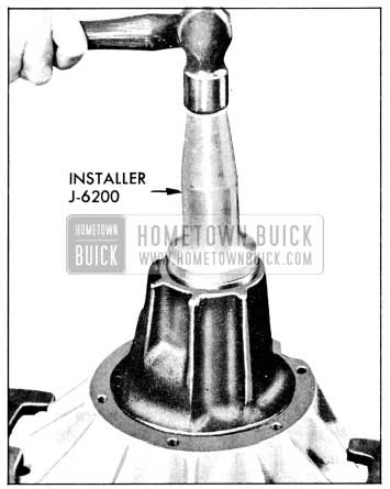
1956 Buick Installing Pinion Seal
Reinstall pinion and bearings carefully in carrier with new thickness pre-load spacers. Install pinion nut and tighten to 80 foot pounds using Torque Wrench J-1313B in outer end of Handle J-6246 as shown in figure 6-23.
- Recheck pinion setting with gauge. Setting for new pinion must be within .001″ of setting marked on pinion. Setting for used pinion should be within .001″ of original setting (as checked before disassembly).
- Recheck pinion bearing pre-load with torque wrench. Pre-load must not exceed 40 inch pounds including drag of lubricated new seal. When pinion pre-load and depth settings are correct, stake pinion nut securely.
- Install oil pump clip on jobs having oil pumps. (70 Series)
Assembly of 1956 Buick Differential Case, Gears and Bearings
Drive differential bearing outer races into case, using Replacer J-6263. See figure 6-30.
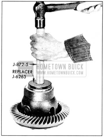
1956 Buick Installing Differential Bearing Outer Race
- Install side gears, pinions, and spherical washers in case. There are no fiat washers behind side gears. If same parts are used, replace in original sides. Install pinion shield and pinion axle. Drive spring pin through hole in pinion axle until flush with case.
- Check matching numbers on ring gear and pinion to make sure the two parts have not been mixed with another gear set. See figure 6-26.
- After making sure that mating surfaces of case and ring gear are clean and free of burrs, bolt ring gear to case using three Studs J-6251 to align parts. See figure 6-31. If same ring gear and case are used, line up marks so they are assembled in same relative positions.
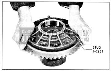
1956 Buick Installing Ring Gear on Differential Case
Do not use lock washers or any substitute bolts.
- First tighten bolts alternately on opposite sides of the case to 25-30 foot pounds torque, then tighten in the same manner to 65-75 foot pounds.
Installation and Adjustment of 1956 Buick Ring Gear and Case Assembly
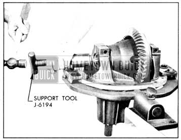
- Before installation of ring gear and case assembly make sure that differential bearing and bearing support surfaces in carrier pedestals are clean and free of burrs. Remove any burrs which might prevent bearings or bearing supports from seating properly.
- Place case assembly and differential bearings in position in carrier. If same bearings are used, replace in original positions. Insert Support Tools J-6194 through the pedestal bores into the bearing inner races. Press tools toward each other to seat them, using hand pressure. If support tools are loose, install pedestal clamp bolts and nuts and tighten lightly until support tools can just be moved by twisting them. If support tools are too tight, loosen them as necessary by slightly wedging pedestals open with chisels. See figure 6-32.
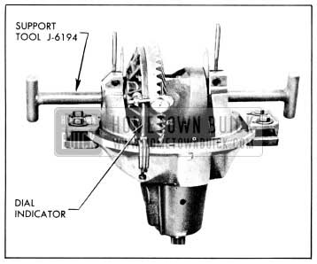
1956 Buick Positioning Differential for Correct Backlash
- Rotate the differential assembly three or four times to seat bearing rollers, then manually adjust the whole assembly sideways to get .008″ gear backlash. The assembly tools may be tapped lightly with a hammer to seat them. Check backlash as follows:
- Mount dial indicator as shown in figure 6-33. Use a small button on indicator stem so that contact can be made near heel end of tooth. Set dial indicator so that indicator stem is as nearly as possible in line with gear rotation and perpendicular to the tooth surface.
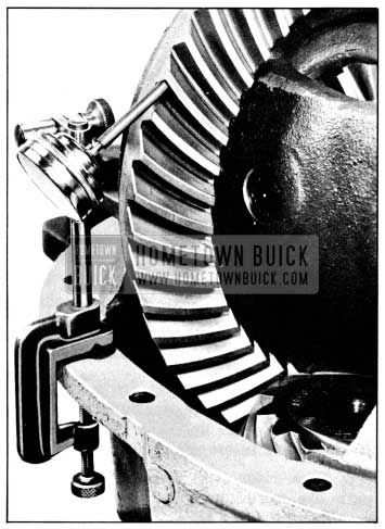
1956 Buick Checking Backlash with Dial Indicator
If stem bears against edge of tooth, or stem is at considerable angle to the line of gear rotation, or at a considerable angle to face of the tooth, a false indication of backlash will be obtained.
- Check gear lash at three or four points around ring gear. Lash must not vary more than .003″ around ring gear. If lash varies over .003″ check for burrs, uneven bolting conditions, or distorted case flange, and make necessary corrections.
CAUTION: Any gear lash check must be mad e with pinion locked to carrier to be sure it cannot turn.- Adjust gear lash at the point of minimum lash to .008″ for all new gears. If original gear set is being reinstalled, the original lash should be maintained.
- Measure with a shim between each bearing and its pedestal. Do not remove support tools for measuring. Select shim that measures .002″ thicker than largest shim that can be inserted for each side; this should pre-load each differential bearing .002″. These shims are furnished to be used singly in thicknesses ranging from .040″ to .082″ by two thousandths. Service shims are marked with their thickness in thousandths.
- Remove support tool farthest from ring gear, insert shim for that side, and replace support tool.
- Place other shim in position for insertion. While keeping a heavy hand pressure on shim, spread carrier pedestals just enough to start shim, using Spreader J-6185.
CAUTION: Do not spread pedestals any farther apart than is absolutely necessary to push differential shim into position. If pedestals are sprung too far, they may take a permanent set. See figure 6-34. Leave support tool in position until after shim is started to keep case assembly from dropping out of line.
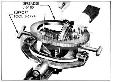
1956 Buick Installing Differential Bearing Shims
- Remove left assembly tool and push shim into final position. Center it first with fingers through pedestal bore, then with a support tool. Remove spreader tool and pedestal wedges.
- Drive each differential bearing support into its pedestal until seated solidly in the bearing, using Support Tool J-6194. See figure 6-35. Tighten pedestal clamp bolts and nuts to 30-40 foot pounds. Secure nuts with cotter pins.
1956 Buick Installing Differential Bearing Supports
- Recheck backlash as in step 3. Final backlash must be .007″-.009″ at point of minimum lash, with not more than .003″ variation around gear.
Disassembly and Inspection of 1956 Buick Differential Pump
- Remove cover plate. Then remove rotor, vanes, priming ring and centering ring. See figure 6-36.
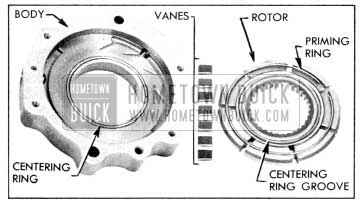
1956 Buick Differential Pump Parts
- If pump is defective, it must be replaced as a unit as no service parts are available for repair.
- Clean all parts in solvent and dry thoroughly. Inspect parts for excessive wear. Check rotor for cracks at the base of vane slots. Check for scoring in the pump body.
Assembly and Installation of 1956 Buick Differential Pump
- Place centering ring in groove in pump body. Place priming ring in body 5o that it is roughly concentric with centering ring.
- Place rotor in pump body so that centering ring groove in rotor engages centering ring.
- Place vanes in pump rotor in the general area between the pump inlet and outlet ports. As each vane is inserted, turn rotor slightly so that another empty slot is in position between the two ports. Be sure that inner corner of vanes engage the priming ring, forcing it inward. See figure 6-37.
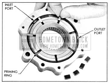
1956 Buick Assembling Differential Pump
- After all seven vanes are assembled in pump, place cover plate over pump face so that all screw holes line up. Then push cover plate on spring pin. Insert screws and tighten evenly.
- Turn rotor with fingers to be sure all parts are operating freely. Then bolt pump to 1956 Buick rear axle carrier.
- Slip outlet pipe under clip and tighten pipe fitting into pump.
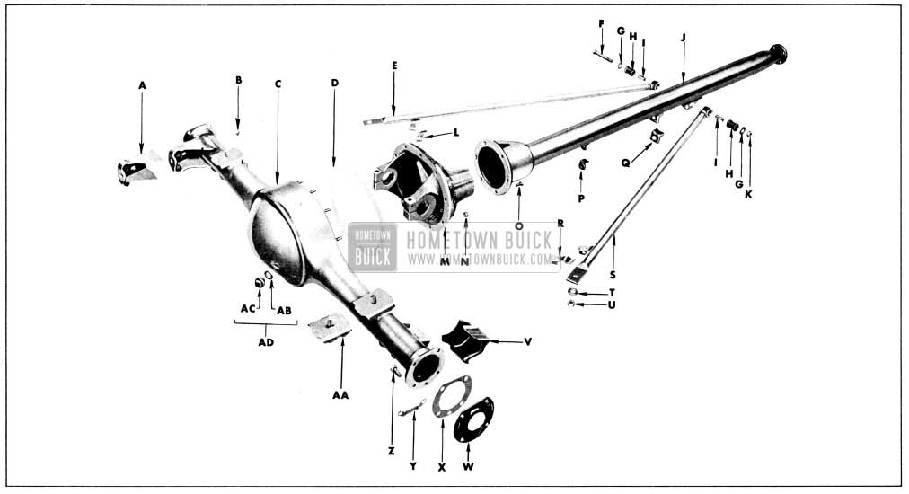
1956 Buick Rear Axle Assembly External Parts
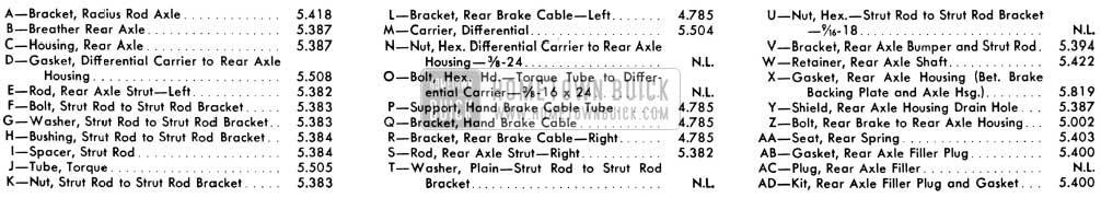
1956 Buick Rear Axle Assembly Legend
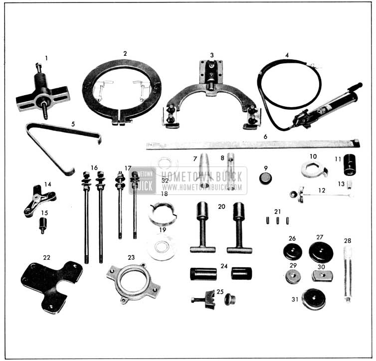
1956 Buick New Tools for Rear Axle
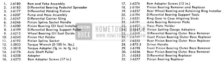
1956 Buick New Tools for Rear Axle Legend
Leave A Comment
You must be logged in to post a comment.