SECTION 13-D 1956 BUICK CONVERTIBLE TOP POWER SYSTEM
13-12 OPERATION OF 1956 BUICK FOLDING TOP
When the control knob is pushed forward, the feed wire is connected to the red motor lead and the motor and pump assembly operate to force the hydraulic fluid through the hoses to the lower ends of the double-acting cylinders. The fluid forces the piston rods out of the cylinders, thus raising the top. The fluid in the top of the cylinders returns to the pump for recirculation to the bottom of the cylinders. When the control knob is pulled rearward, the feed wire is connected to the dark green motor lead and the motor and pump assembly operate in a reversed direction to force the hydraulic fluid through the hoses to the top of the cylinders. The fluid forces the piston rods into the cylinders, thus lowering the top. The fluid in the bottom of the cylinders returns to the pump for recirculation to the top of the cylinders.
13-13 CHECKING PROCEDURES
Mechanical Checking Procedure
If there is a failure in the 1956 Buick Hydro-Lectric system and the cause is not evident, the mechanical operation of the top should first be checked. If the folding top assembly appears to have a binding action, disconnect the lift cylinder piston rods from the top linkage and then manually lower and raise the top. The top should travel through its down and up cycle without any evidence of a binding action. If a binding action is noted when the top is being locked at the header, check the alignment of the door windows, ventilators, and rear quarter windows with relation to the side roof rail weatherstrips. Make all necessary adjustments for correct top alignment. If the top does not operate hydraulically after all mechanical problems have been corrected, the Hydro-Lectric system should then be checked for electrical or hydraulic failure.
Checking Operation of 1956 Buick Convertible Top Lift Cylinder
- Remove the rear seat cushion and folding top compartment side panel assembly.
- Operate the folding top control switch and observe the lift cylinders during the “up” and “down” cycles for these conditions:
- If the movement of the cylinder rods is not coordinated or sluggish when the motor is actuated, check the hydraulic hoses from the motor and pump to the cylinders for kinks.
- If one cylinder rod moves slower than the other, the cylinder with the slow moving rod is defective and should be replaced.
- If both cylinder rods move slowly, or do not move at all, check the pressure of the pump. See subparagraph d below.
Checking Fluid Level in Reservoir
- Operate top to raised position.
- Remove motor and pump shield from rear compartment.
- With a straight-bladed screw driver remove filler plug indicated at “C” in figure 13-17.
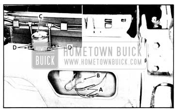
1956 Buick Pump and Motor Connections
- Insert dip stick into reservoir. Fluid level should be two (2) inches from top of reservoir. If fluid is low, add hydraulic fluid Delco #11 (G. M. Hydraulic Brake Fluid Super #11).
- Reinstall filler plug and pump and motor shield.
Checking Pump Pressure
- Remove the motor and pump assembly from the rear compartment as described in par. 13-14 (a).
- Install plug in one port and pressure gauge in port to be checked as indicated in figure 13-18.
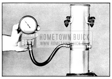
1956 Buick Checking Pump Pressure
- Actuate motor with an applied terminal voltage within the range of 9.5 volts to 11.0 volts. Pressure gauge should show a pressure between 240 psi. and 280 psi.
- Check pressure in other port. NOTE: A difference in pressure readings may exist between the pressure port for the top of the cylinders, and the pressure port for the bottom of the cylinders. This condition is acceptable if both readings are within the limit of 240 psi. and 280 psi.
- If the pressure is not within the specified limits, the unit is defective and should be repaired or replaced, as required.
13-14 ROTOR-TYPE PUMP AND MOTOR ASSEMBLY
Removing Pump and Motor Assembly
- Operate the 1956 Buick convertible top to the full “up” position.
- Disconnect the negative battery cable.
- Remove the rear seat cushion and back.
- From inside the body, disconnect motor wires at “A” and ground wire at “B” in figure 13-17.
- Working in the rear compartment, remove the screws securing motor and pump shield and remove shield. Disengage hydraulic hoses from retaining tabs on rear seat back panel.
- Remove filler plug indicated at “C” in inset of figure 13-17 to vent reservoir, then reinstall plug.
NOTE: Venting of the reservoir is necessary in this sealed -in unit to equalize air pressure in the reservoir to that of the atmosphere. This operation prevents the possibility of the hydraulic fluid being forced under pressure from disconnected lines and causing damage to trim or body finish.
- To facilitate removal, apply rubber lubricant to motor and pump assembly attaching grommets “D,” then disengage grommets from floor pan.
- Disconnect hydraulic lines from the pump and plug open fittings to prevent leakage of fluid. Use a cloth to absorb any fluid dripping from the lines.
Removing Reservoir Tube
- Scribe a line across the pump end plate, reservoir tube, and reservoir tube end plate to ensure correct assembly of parts.
- With a straight-bladed screw driver, remove filler plug indicated at “A” in figure 13-19. Note the sealing ring around plug.
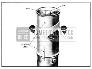
1956 Buick Removing Reservoir Tube
- Drain fluid from reservoir into a clean container.
- With suitable tool, remove bolt indicated at “B” in figure 13-19. Note the sealing rings around bolt, reservoir end plate, and between end of reservoir tube and pump assembly.
Installing Reservoir Tube
- Position sealing ring on pump and assemble reservoir tube to pump according to scribe marks.
- Position sealing ring on tube end plate and place end plate on reservoir tube, lining up the scribe marks. Install and tighten attaching bolt.
- Fill reservoir tube with hydraulic fluid Delco #11 (G. M. Hydraulic Brake Fluid Super #11). See paragraph 13-13 (c).
- Reinstall filler plug.
Installing Pump and Motor Assembly
- If a replacement unit is being installed, fill reservoir with specified hydraulic fluid Delco #11 (G. M. Hydraulic Brake Fluid Super #11).
- Connect hydraulic hoses to pump unit.
- Connect battery and electrical leads to motor. Operate top through its up and down cycle.
- Check connections for leaks and check fluid level in reservoir. See paragraph 13-13 (c) for proper level.
- Engage attaching grommets in panel.
- Reinstall previously removed parts.
I have a 1956 buick super convertible that has latch problems! Top works loose when driving and I have to tighten handle frequently! Anyone there have any ideas how to correct! No one locally has helped! 303-472-1914 georgechekay@q.com thx local shop says problem in roof rail adjustment, but assembly is rivited together and they don’t want to mess with it!