SECTION 3-H 1956 BUICK ROCHESTER 4-BARREL CARBURETOR
3-27 DESCRIPTION AND OPERATION OF 1956 BUICK ROCHESTER 4-BARREL CARBURETOR
General Description
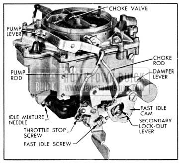
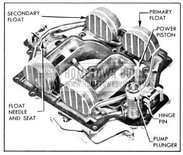
The Rochester Model 4GC used on the Series 50-60-70 engine is a 4-barrel downdraft type which provides the advantages of a compound installation of two 2-barrel carburetors in one compact unit. See figure 3-75.
1956 Buick Rochester 4-Barrel Carburetor
To aid description and the proper identification of parts the 1956 Buick Rochester 4-barrel Carburetor is considered to be divided into a primary section and a secondary section.
The primary section covers the 2-barrelled forward half of the 1956 Buick Rochester 4-barrel Carburetor assembly. This section is essentially a complete 2-barrel carburetor containing a float system, idle system with adjustable needle valves, main metering system, power system, and accelerating system. This section also includes an accelerator vacuum switch for starting the engine, and the automatic choke mechanism.
The secondary section covers the 2-barrelled rearward half of the 1956 Buick Rochester 4-barrel Carburetor assembly. This section is essentially a supplementary 2-barrel carburetor which cuts in to assist the primary section when a pre-determined throttle opening and engine RPM are reached. This section contains a float system, a non-adjustable idle system, and a main metering system. It has a separate set of throttle valves and a set of auxiliary valves, which are located in the barrels above the throttle valves.
The primary throttle valves are operated by the accelerator pedal and the connecting throttle linkage. The secondary throttle valves are operated by the primary throttle valve shaft through delayed action linkage which permits a predetermined opening of the primary valves before the secondary valves start to open. Action of the linkage then causes both sets of throttle valves to reach the wide open position at the same time.
The starter switch, which is operated by a lever on the primary throttle valve shaft, is fully described in paragraph 10-30. The other systems of the 1956 Buick Rochester 4-barrel Carburetor are described in the following subparagraphs.
Operation of Float Systems
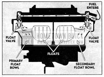
Each section of the 1956 Buick Rochester 4-barrel Carburetor has a separate and independent float system, consisting of a float chamber formed by a partition in the main body, a 2-pontoon float, a needle valve seat and valve. Fuel enters the 1956 Buick Rochester 4-barrel Carburetor through a strainer in the inlet port in the secondary side of the air horn. From this point fuel flows to the separate float chambers through a horizontal passage in the air horn. See figure 3-76.
1956 Buick Primary and Secondary Float Systems
When the fuel reaches the prescribed level in each float chamber the float moves the needle valve against its seat to shut off the flow of fuel. The needle valves are connected to the float levers by clips.
The joint between the air horn and the main body is sealed by a gasket, and the float chambers are vented by passages which are calibrated to provide proper air pressure above the fuel under all operating conditions. These passages in the air horn lead into the throat of the air horn, and to outside atmosphere. The external vents permit fumes to escape from the float chambers when the engine is stopped after extremely hot operation.
Operation of Idle (Low Speed) Systems
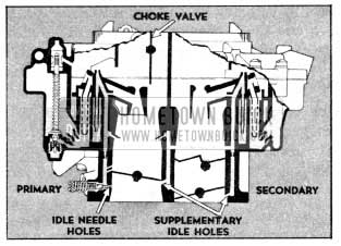
Each barrel of the 1956 Buick Rochester 4-barrel Carburetor has a separate idle system but the general operation is identical in all barrels. The idle system in each barrel supplies fuel to the engine whenever the position of the throttle valve is such that suction is created at the idle discharge holes in the throttle body.
Suction on an idle discharge hole causes fuel in the float chamber to flow through the main metering jet and upward into the idle tube which meters the fuel. Bleed holes permit air to enter at the top and side of the idle passage in the cluster so that a mixture of fuel and air passes down the idle channel to the idle discharge holes. Additional air is drawn into the fuel-air mixture in the idle channel through an auxiliary air bleed which is in the main body. See figure 3-77.
1956 Buick Primary and Secondary Idle Systems
When the throttle valve is closed, the fuel air mixture is supplied through the lower idle discharge holes only, since the upper holes are above the valve and are not affected by suction. As the throttle valve is opened, suction is also placed on the upper idle discharge holes which then feed additional fuel-air mixture into the engine. With continued opening of the throttle valve the suction on the idle discharge holes tapers off until a point is reached where the idle system no longer supplies fuel-air mixture. Before this point is reached however, the main metering system has begun to supply fuel, as described later.
The auxiliary air bleeds discharge fuel after the idle systems cease to operate, thereby keeping fuel immediately available in the idle channels at a point very near the idle discharge holes and also enriching the mixture being delivered by the main metering system.
In the primary section, the quantity of fuel air mixture supplied through the lower idle discharge holes is controlled by the idle needles, which may be adjusted to provide smooth engine idle operation. In the secondary section, the quantity of idle fuel-air mixture is controlled by the fixed size of discharge holes located in the rear of both the primary and secondary throttle bores.
Operation of Main Metering Systems
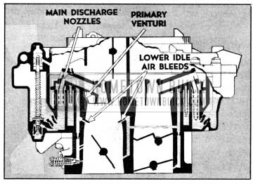
Each barrel of the 1956 Buick Rochester 4-barrel Carburetor has a separate main metering system; however, the operation of all systems is identical. The main metering system in each barrel supplies fuel to the engine whenever the position of the throttle valve is such that the incoming air stream creates suction on the main discharge nozzle.
Air entering the barrel through the air horn passes through the venturi tubes which increase the velocity of the air and create a suction on the main discharge nozzle. This causes fuel to flow from the float chamber through the main metering jet into the main discharge nozzle. Air is drawn in through the high speed bleeder so that a mixture of fuel and air is discharged from the main discharge nozzle into the air stream passing through the small venturi in the barrel of the 1956 Buick Rochester 4-barrel Carburetor. See figure 3-78.
1956 Buick Primary Main Metering System
The main discharge nozzle is designed so that if any vapor bubbles are formed in the hot gasoline the vapors will follow the outside channel around the main discharge nozzle and escape through the high speed bleeder instead of passing through the main discharge jet.
The main metering systems in the primary section control the flow of fuel during the intermediate or part throttle range of operation and up to approximately 85 MPH when the car is accelerated gradually. The secondary throttle valves remain closed until the primary valves have opened approximately 40-44 degrees, after which they are opened proportionately so that all valves reach the wide open position at the same time. While the secondary throttle valves are closed, the auxiliary valves located above them are held closed by the counterweight on the auxiliary valve shaft lever (fig. 3-78); therefore, there is not sufficient air flow through the barrels to operate the main metering systems in the secondary section.
When the secondary throttle valves are open and engine speed is about 2000 RPM, the resulting air flow through the secondary barrels forces the auxiliary valves open because their supporting shaft is located off-center in the barrels. When the auxiliary valves are open the main metering systems in the secondary section also supply fuel to the engine. See figure 3-79.
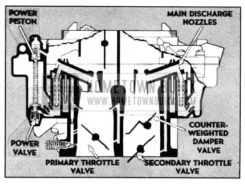
1956 Buick Main Metering and Power Systems
Operation of the Power System
For maximum power under load or for all speeds above approximately 90 MPH, a richer mixture is required than that necessary for normal throttle opening. This additional fuel is provided by one power system connected to the main metering systems in the primary section of the 1956 Buick Rochester 4-barrel Carburetor. See figure 3-79.
The power piston cylinder in the air horn of the 1956 Buick Rochester 4-barrel Carburetor is connected by a channel to the face of the mounting flange so it is subject to intake manifold vacuum. At part throttle position the vacuum is sufficient to hold the power piston in its “up” position against the tension of the piston spring. When the throttle valves are opened to a point where manifold vacuum drops to approximately 9 to 7 inches of mercury and additional fuel is required for satisfactory operation, the piston spring moves the power piston down to open the power valve. This allows additional fuel to enter the main discharge nozzles in the primary section through calibrated restrictions located below the main metering jets. See figure 3-79.
Operation of the Accelerating System
For smooth and rapid acceleration it is necessary to supply an extra quantity of fuel momentarily when the throttle is opened suddenly. This is accomplished by one accelerating pump piston which is directly connected to the primary throttle shaft lever by means of a rod and pump lever.
When the throttle is closed, the pump piston moves up and draws a supply of fuel from the float chamber through the inlet strainer, past the inlet ball check valve and into the pump cylinder. When the throttle is opened, the piston on its downward stroke exerts pressure on the fuel which closes the inlet check ball and opens the outlet check ball. A metered quantity of fuel is then discharged through the pump discharge nozzles into each barrel in the primary section of the 1956 Buick Rochester 4-barrel Carburetor. This occurs only momentarily during the accelerating period. The pump duration spring which is compressed by the downward movement of the pump linkage against the resistance of the fuel provides a follow-up action so that the discharge carries out over a brief period of time. A ball check in the accelerator pump plunger acts as a vapor vent to prevent vapor pressure from forcing fuel from the pump discharge holes during extreme heat periods. Downward movement of the plunger, however, seats the ball and allows normal operation of the accelerating system. See figure 3-80.
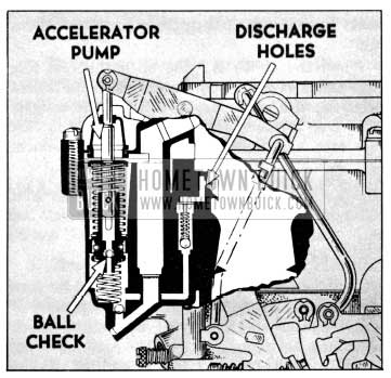
1956 Buick Rochester Accelerating System
When the desired speed is reached and the throttle is held in a fixed position, the pressure on the fuel decreases sufficiently so that the outlet check ball closes and fuel ceases to discharge from pump nozzles. Thus a quantity of fuel is maintained in the channel adjacent to the outlet check ball where it is immediately available for future requirements.
3-28 DESCRIPTION AND OPERATION OF ROCHESTER AUTOMATIC CHOKE
General Description
The automatic choke mechanism is contained in the primary section of the 1956 Buick Rochester 4-barrel Carburetor. It consists of a choke valve mounted on a shaft in the 1956 Buick Rochester 4-barrel Carburetor air horn connected through linkage to a thermostat mounted on the 1956 Buick Rochester 4-barrel Carburetor main body. The thermostat contains a bi-metal spring and a vacuum actuated piston. A fast idle rod connects the choke valve to a fast idle cam on the throttle body. A heat pipe connects the choke housing to a heat stove in the right exhaust manifold.
The choke valve is mounted off-center in the choke stem so that the force of the air stream passing through the air horn tends to move the valve to the open position. A short lever mounted on the choke stem in the choke housing is engaged by the free outer end of the thermostat which, when cold, tends to close the choke valve. The piston, which is actuated by intake manifold vacuum, is connected by a link to the short lever on the choke stem and tends to open the choke valve when the engine fires.
The heat stove in the exhaust manifold heats the air which is drawn through it and the heat pipe into the choke housing. Restrictions in the choke housing permit manifold vacuum to draw the air into the choke housing to heat the thermostat.
The fast idle cam is connected by the fast idle rod to a lever on the outer end of the choke stem so that it is rotated as the choke valve moves. In closed throttle position, the fast idle screw bears against one edge of the fast idle cam which has a number of steps of different heights to give different amounts of throttle opening, depending on positions of the cam and choke valve.
Choke Operation-Cold Engine
When the engine becomes cold the choke thermostat also becomes cold and increases its spring tension sufficiently to close the choke valve. It is prevented from closing the valve, however, because the fast idle screw holds the fast idle cam in the slow idle position; consequently, the choke valve is held partially open.
When the accelerator pedal is depressed to start the engine, the throttle stop screw is lifted clear of the fast idle cam and the thermostat then closes the choke valve. When the engine starts, intake manifold vacuum causes the piston to partially open the choke valve against the spring tension of the thermostat, thereby admitting sufficient air to give a satisfactory running mixture.
When the accelerator pedal is released after starting the engine, the fast idle screw comes to rest against a step of fast idle cam which was rotated to the fast idle position by the closing of choke. This provides proper throttle opening to prevent stalling of the cold engine.
If the throttle is partially opened while the running engine is cold, the increased force of air flow against the off-set choke valve will open the valve against the spring tension of the thermostat. These opposing forces balance the choke valve at a position which provides the required choke action without causing loading or an excessively rich mixture.
Choke Operation-Warm-Up Period
As the engine and exhaust manifold warm up, warm air is drawn through the h eat pipe into the choke housing by manifold vacuum. This warms the thermostat, causing it to reduce its spring tension on the choke valve in proportion to the increase in temperature. This, in turn, allows the choke valve to be opened by the combined forces of air velocity on the valve and vacuum on the choke piston.
When the throttle is opened and the fast idle screw is lifted from the fast idle cam, the fast idle rod and cam drop by their own weight to bring a lower step into position for the throttle stop screw. The engine will then run at a lower speed at closed throttle.
Choke Operation-Hot Engine
When the engine reached normal operating temperature, the choke thermostat is heated to the point where it no longer exerts any spring tension on the choke valve. The choke valve is in the wide open position and the fast idle cam is in the slow idle position so that the fast idle screw misses the cam completely. The throttle stop screw now takes over in determining curb idle speed.
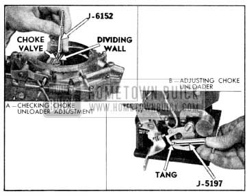
Choke Unloader Operation
If the engine becomes flooded for any reason, the choke valve can be partially opened by depressing the accelerator pedal to the full extent of its travel. This causes a tongue or arm on the throttle lever to contact and rotate the fast idle cam, which forces the choke valve open.
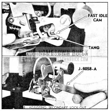
Secondary Lock-out Operation
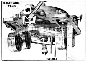
The secondary section does not have a choke valve in the air horn. In order to prevent air entering the 1956 Buick Rochester 4-barrel Carburetor through the secondary side during the engine warm-up period it is necessary to block the movement of the secondary throttle valves by means of the lock-out slot in the fast idle cam.
When the choke valve is in any position except wide open, it holds the fast idle cam up from its lowest position. This causes a lock-out slot in the fast idle cam to engage a tang on the secondary throttle shaft lever which prevents the secondary throttle valves from opening.
When the choke is wide open the fast idle cam and lock-out slot plate drops to its lowest position; the secondary throttle shaft tang is then free to move along a contour in the fast idle cam and the secondary valves can open.
3-29 ADJUSTMENT OF FAST IDLE CAM, CHOKE UNLOADER, AND SECONDARY THROTTLE LOCK-OUT
- Close throttle so that fast idle screw contacts second step of fast idle cam with side of screw against high step of cam, then check clearance between choke valve and air horn dividing wall using (.140″) end of Gauge J-6152. See figure 3-81.
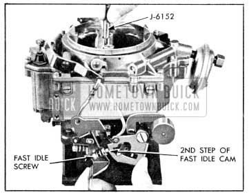
1956 Buick Checking Rochester Fast Idle Cam Adjustment
1956 Buick Adjusting Rochester Fast Idle Cam
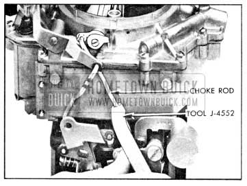
1956 Buick Rochester Choke Unloader Adjustment
1956 Buick Secondary Lock-Out Adjustment
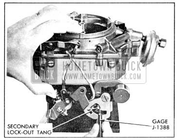
1956 Buick Secondary Contour Adjustment
3-30 DISASSEMBLY, CLEANING, AND INSPECTION OF 1956 BUICK ROCHESTER 4-BARREL CARBURETOR
Disassembly of 1956 Buick Rochester 4-barrel Carburetor
- Remove fuel filter.
- Remove spring clip from upper end of intermediate choke rod. Then remove intermediate choke rod. See figure 3-86.
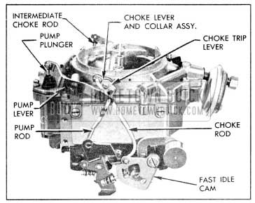
1956 Buick Exterior Linkage
1956 Buick Rochester Air Horn Parts
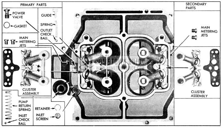
1956 Buick Main Rochester Carburetor Body Parts
Cleaning 1956 Buick Rochester 4-barrel Carburetor Parts
Regardless of the number of new parts that are used in rebuilding a 1956 Buick Rochester 4-barrel Carburetor, the job in the end will not be satisfactory unless all metal parts are thoroughly cleaned. Because of the nature of 1956 Buick Rochester 4-barrel Carburetor parts, with numerous small passages subject to fouling due to tenacious carbon and gum deposits, ordinary cleaning processes are entirely inadequate. The correct procedure is to use a cleaning bath in which metal parts can be immersed and “soaked” for sufficient time after disassembly to thoroughly clean all surfaces and channels.
Bendix Metalclene has been developed especially for cleaning carburetors, and is recommended for this purpose. Regardless of the cleaning material used, however, be sure to thoroughly rinse the parts in kerosene, distillate, or white gasoline to remove all gummy deposits that have been softened by the cleaner.
Inspection of 1956 Buick Rochester 4-barrel Carburetor Parts
After cleaning, all parts should be carefully inspected for wear or damage as follows:
- Choke Parts. It is very necessary for the vacuum piston and cylinder to be clean and free of burrs or scores. Do not use any abrasive material for cleaning these parts.
Check clearance of choke stem in bearings of air horn. If stem or bearings are worn so that excessive clearance exists, replace the worn parts. Make sure that bearings are free of gum.
If thermostat is distorted or damaged it must be replaced with a new thermostat cover with thermostat assembly. The thermostat is not furnished separately because the index mark is stamped on cover after installation of thermostat, to insure proper calibration.
- Float Needle Valve and Seat. Because of the wear that normally occurs in these parts and the necessity of having a tight seating valve, it is advisable to replace these parts if the 1956 Buick Rochester 4-barrel Carburetor has been used for considerable mileage. Even if mileage is low, replace these parts if needle is grooved or seat is damaged.
- Vacuum Power Piston and Power Valve. Make certain that the surface of the piston is thoroughly clean. Do not use any abrasive material for polishing the piston surface. Inspect for wear or damage. Replace if necessary. Test power valve for tight seating by sucking on the upper end. Replace if doubtful.
- Main Body. Make certain the main body is thoroughly clean and that all passages are free of foreign material.
- Cluster Assemblies. Inspect each main discharge nozzle and venturi for damage. Check idle jet tubes and upper idle air bleeds by looking through tubes toward a light. NOTE: If any part of a cluster assembly is damaged, the whole cluster assembly must be replaced as a unit.
- Pump Piston and Check Valve Balls. Inspect pump piston leather for cracks, creases, turned edges, or other damage. Test relief valve in piston for tight seating by blowing on lower end of piston; if valve is seating tightly it will not be possible to blow through it.
It is advisable to replace pump inlet and discharge channel check valve balls since these parts are small and difficult to inspect.
Inspect check valve ball seats in main body with a good light. If a seat appears rough, place ball in seat and tap lightly to swage a good seat, then discard the ball.
- Idle Discharge Holes and Idle Needle Valves. Be sure that the idle discharge holes, the air bleeders, and the barrels of the throttle valve body are clean of all carbon deposits. A comparatively small amount of carbon in barrel may have the effect of decreasing the bore sufficiently to prevent the throttle valves from resting at the correct angle when closed. This can have serious effects on performance because the distance from the throttle valve, when closed, to the edge of the idle discharge hole must be kept within close limits to the established dimension.
Make sure that the holes drilled through each barrel of the throttle body are clear. These holes permit vapors to escape rather than rising into the air cleaner when engine is stopped.
Inspect seats for idle needle valves for scoring or other damage. If ends of needle valves are grooved or bent, replace the valves.
- Throttle Valves, Throttle Levers and Shafts. See that throttle valves are not bent and do not have burrs or sharp edges.
Inspect throttle lever and shaft assemblies for wear on bearing surfaces. Check pump rod hole for wear and also see that levers are not loose on shafts.
Check action of throttle valves and shafts for free movement. Check for correct wide open position and for correct alignment in throttle bore when closed.
NOTE: If throttle valves or shafts are damaged or worn excessively, the throttle body and valve assembly must be replaced as a unit.
- Accelerator Vacuum Switch. Disassemble, clean, inspect, and re-assemble vacuum switch as described in paragraph 10-30.
3-31 ASSEMBLY AND ADJUSTMENT OF 1956 BUICK ROCHESTER 4-BARREL CARBURETOR
Assembly of 1956 Buick Rochester 4-barrel Carburetor
When assembling the 1956 Buick Rochester 4-barrel Carburetor use all new gaskets and any additional new parts found to be necessary during inspection. Calibrated parts must be as specified for carburetor CODE number.
- Install auxiliary throttle shaft. Install fast idle cam attaching screw without fast idle cam, then check vertical measurement from shoulder of screw to top edge of counterweight lever using number one (51/64) end of Gauge J-6153. See figure 3-89, (View B).
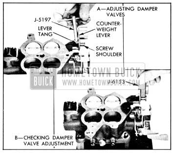
1956 Buick Damper Valve Adjustment
- With air horn inverted and gasket in position, place Float Gauge J-6151 (1 35/64″ over highest part of each float. See figure 3-90.
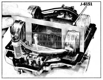
1956 Buick Rochester Float Adjustment
1956 Buick Float Drop Adjustment
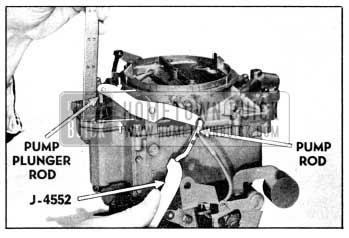
1956 Buick Pump Rod Adjustment
- Push fast idle cam to full up position so that fast idle screw contacts high step of cam. See figure 3-93.
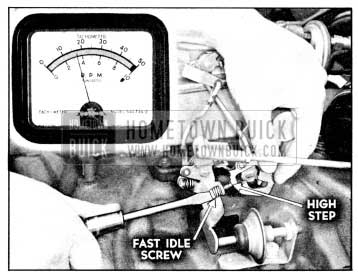
1956 Buick Adjusting Fast Idle
Leave A Comment
You must be logged in to post a comment.