SECTION 13-E 1956 BUICK POWER FRONT SEAT ASSEMBLY
13-15 GENERAL DESCRIPTION OF 1956 BUICK FRONT SEAT ASSEMBLIES
Three types of 1956 Buick seat adjusters are available for the front seat assembly. On all 1956 Buick models except 66C, 56C, 73, 76C, 76R, the manual seat adjuster is installed as standard equipment and the six-way electric seat adjuster is available as an option. On models 66C, 56C, 73, 76C, 76R, the electric horizontal seat adjuster is installed as standard equipment and the six-way electric seat adjuster is available as an option. The removal and installation of a seat equipped with the manual seat adjuster or electric horizontal seat adjuster is similar to the procedure outlined for these seats on the past sedan styles. The removal and installation of a seat equipped with the six-way seat adjuster is outlined in this section.
13-16 SIX-WAY TILT-TYPE POWER OPERATED SEAT ADJUSTERS
The new 1956 Buick seat adjusters provide three (3) basic seat movements: 1. Horizontal, 2. Vertical, and 3. Forward and rearward tilt. The adjusters are operated by an actuator assembly consisting of a twelve (12) volt reversible motor and relay, and a gear box and jack screw. The regulator motor is controlled by a three (3) button switch located on the front seat left side panel. Three spinning nut and solenoid assemblies located on the regulator jack screw transmit movement to the seat adjusters by means of a torque tube assembly and links. In each of the spinning nut assemblies is a free-wheeling spinning nut which is mounted in ball bearings and free-wheels (rotates) with the jack screw unless locked out of free-wheeling by the solenoid located on top of the spinning nut. When the spinning nut is locked out of free-wheeling the spinning nut assembly moves forward or rearward on the jack screw; thereby, transmitting movement to the seat adjusters by means of the connecting links and torque tube assembly. The seat assembly may be removed from the adjusters as described in paragraph 13-18, to perform trim operations on the seat or to replace a seat or to replace a seat adjuster actuator solenoid. When an adjuster, torque tube, actuator or spinning nut assembly is to be removed, the seat assembly (including seat adjusters and actuator) should be removed from the body, as described in paragraph 13-17.
NOTE: When checking or testing the six way tilt-type power operated seat adjuster, it is imperative that current does not pass through the motor or spinning nut assembly solenoid coils for more than sixty (60) seconds at any one time. Failure to adhere to this note will result in possible short circuits or burned-out motors.
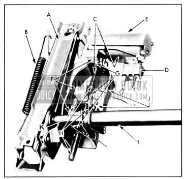
1956 Buick Six-Way Power Seat Adjuster
- Seat Adjuster Assembly-Right
- Seat Adjuster Counter Balance Spring
- Seat Adjuster Actuator Assembly
- Seat Adjuster Actuator Motor Relay
- Seat Adjuster Actuator Motor Cover
- Seat Adjuster Actuator Spinning Nut Solenoids
- Seat Adjuster Actuator Spinning Nut Assemblies.
- Seat Adjuster Actuator Roll Pins (on jack screw)
- Seat Adjuster Torque Tube Assembly
- Seat Adjuster Spinning Nut Mounting Supports
- Center Spinning Nut Anti-Creep Spring
13-17 REMOVAL AND INSTALLATION OF 1956 BUICK SEAT ASSEMBLY INCLUDING SEAT ADJUSTERS
- Operate 1956 Buick seat to raised position.
- Under front of seat disconnect adjuster control wire harness from adjuster feed wire harness and detach control harness from clip on floor pan. Disconnect lighter feed wire and detach wire from clips on floor pan.
- Remove 1956 Buick seat adjuster to floor pan bolts, then with aid of helper lift seat assembly, with adjusters and actuator assembly attached, from body.
- To install, reverse removal procedure. Make sure ground wire is secured under seat adjuster floor pan bolt. IMPORTANT: When installing seat assembly to body, carefully align seat adjuster attaching holes with attaching holes in floor pan to prevent possible binding of seat adjuster linkages. Seat adjusters should be parallel when properly aligned.
After installation of 1956 Buick seat assembly check all six (6) operations of seat to extreme limit of each position.
13-18 REMOVAL AND INSTALLATION OF 1956 BUICK SEAT ASSEMBLY LESS SEAT ADJUSTERS
- Operate seat to fully raised position and midway between full forward and rearward horizontal positions. Remove both right and left seat side panels.
- Under front of seat disconnect control wire harness from adjuster feed wire harness. Disconnect lighter feed wire and detach wire from clip on floor pan: remove ground wire from under seat adjuster bolt.
- At both adjusters remove front and rear seat adjuster-to-seat frame attaching bolts at locations “A” and “B” as shown in figure 13-21.
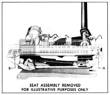
1956 Buick Seat to Adjuster Bolt Points
Make sure ground wire is secured under seat adjuster floor pan bolt. After installation of seat assembly check all six (6) operations of seat to extreme limit of each position.
13-19 REMOVAL AND INSTALLATION OF 1956 BUICK SEAT ADJUSTER
- Remove 1956 Buick seat assembly (including seat adjusters and actuator unit) as previously described. Place seat assembly upside down on a covered bench.
- Remove seat side panel and counterbalance spring from adjuster being removed. Support torque tube assembly, as shown in figure 13-22, on side of seat from which adjuster is being removed.
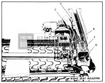
1956 Buick Removing Seat Adjuster Linkage
1956 Buick Removing Seat Adjuster
13-20 REMOVAL AND INSTALLATION OF ADJUSTER ACTUATOR ASSEMBLY
- Operate seat midway between forward and rearward horizontal positions. Operate front of sot to “up” position and rear of seat midway between “up” and “down” position. Remove both seat side panels.
- Remove seat assembly (including seat adjusters and actuator assembly) as previously described. Place assembly upside down on a covered bench. Remove both right and left seat adjuster counterbalance springs.
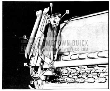
- Check that all spinning nut attaching screws, indicated at “A,” “B” and “C” are accessible for removal. If screws are not accessible, hook up control harness feed wire to power and ground seat frame; hook up control switch, then operate actuator to position spinning nuts so that all screws are accessible. Note position of spinning nuts so they can be reinstalled in same position. See figure 13-24.
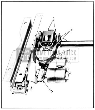
1956 Buick Removing Actuator Assembly
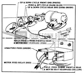
1956 Buick Actuator Wiring Hook-Up
1956 BUICK SEAT WIRING DIAGRAMS
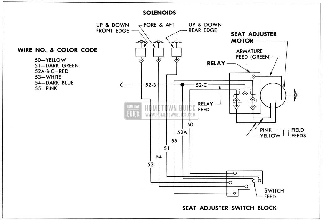
1956 Buick Six-Way Seat Electrical System
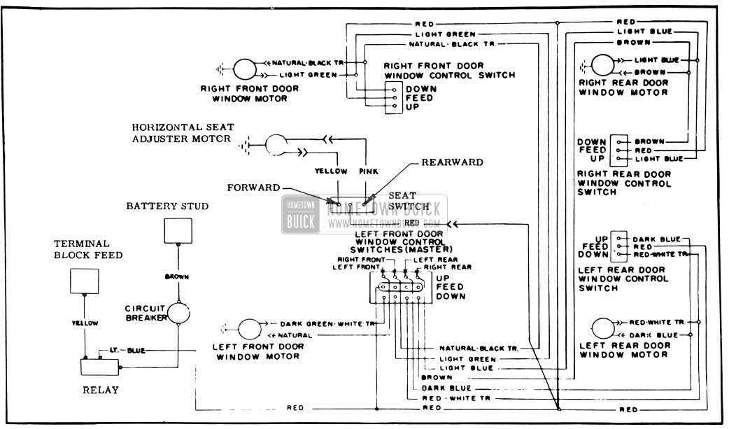
1956 Buick Power Window and Horizontal Power Seal Electrical System
Leave A Comment
You must be logged in to post a comment.