SECTION 3-G 1956 BUICK STROMBERG 2-BARREL CARBURETOR AND AUTOMATIC CHOKE
3-23 DESCRIPTION AND OPERATION OF 1956 BUICK STROMBERG 2-BARREL CARBURETOR
General Description
The WW Stromberg carburetor used on Series 40 engines is a 2-barrel down draft, offset bowl type. See figure 3-56.
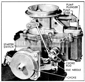
1956 Buick Stromberg WW Carburetor Assembly
It contains a float system, idle (low speed) system, main metering (high speed) system, power system, accelerating system, and automatic choke. An accelerator vacuum switch, which is part of the cranking motor control circuit, is incorporated in the 1956 Buick Stromberg 2-barrel Carburetor assembly.
Air is supplied to both barrels of 1956 Buick Stromberg 2-barrel Carburetor through the air horn which has one inlet and contains the choke valve. Fuel is supplied to both barrels from one float chamber. The float bowl is on the forward side of both barrels and contains a single float and lever assembly which actuates a float needle valve. The accelerating pump discharge nozzle in each barrel is supplied with fuel from one pump located in the float chamber. The power system for both barrels is controlled by one vacuum power piston.
Except as noted above, each barrel forms a complete 1956 Buick Stromberg 2-barrel Carburetor system. Each barrel contains an idle system with adjustable needle valve, a main metering system, accelerating pump discharge nozzle, primary and auxiliary venturi, and a throttle valve. The throttle valves of both barrels are mounted in line on one stem. The dual construction provides the advantages of two carburetors in one compact unit. The dual carburetor and dual intake manifold provides more uniform distribution of fuel to all cylinders than would be possible with one single barrel carburetor.
The throttle body has a small vent in each barrel just above the throttle valve to permit the escape of any excess fuel or vapor which might accumulate due to percolation while idling or after shutting off an engine during very hot weather.
Operation of each system of the WW Stromberg carburetor is described in the following subparagraphs. The starter switch is described in paragraph 10-30.
Operation of Stromberg Float System
Fuel enters the 1956 Buick Stromberg 2-barrel Carburetor at the gasoline connection and flows through the needle valve seat into the float chamber. When the fuel reaches the prescribed level in float chamber, the float presses the needle valve against its seat to shut off the flow of fuel. Thereafter, the fuel is maintained at the prescribed level by opening and closing of the needle valve as required. The float lever is hinged on a fulcrum pin which is retained in the float bowl by a clip. See figure 3-57.
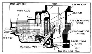
1956 Buick Float and Idle Systems
The float chamber is vented externally through a port in air horn to allow fuel to be smoothly withdrawn through the various systems.
Operation of Stromberg Idle (Low Speed) System
Fuel is delivered to the engine through the idle system at closed throttle and light load speeds up to approximately 20 MPH. The idle system also partially controls fuel supply for light load speeds up to approximately 30 MPH.
The operation of the idle system in each barrel of the 1956 Buick Stromberg 2-barrel Carburetor in identical. Fuel flows from the float chamber through main metering jet and upward through the idle tube which meters the fuel. From the idle tube it flows through a connecting channel where air from the idle air bleeder is mixed with it so that a mixture of air and fuel passes down the idle channel to the idle discharge holes. Additional air is drawn into the fuel air mixture in the idle channel through the secondary air bleeder. See figure 3-57.
On idle or closed throttle operation, the fuel air mixture is drawn only from the lower or primary idle discharge hole due to high suction at this point. As throttle valve is opened, suction is also placed on the upper or secondary idle discharge holes to feed additional fuel. Fuel supplied through the idle discharge holes begins to diminish when the throttle valve is opened to the point where the main metering system begins to supply fuel, as described below, until a throttle position is reached where the idle system ceases to function.
The idle needle valve controls the quantity of fuel that is supplied through the primary idle discharge hole, thereby affecting the final fuel air ratio supplied to the engine while the idle system is in operation.
Operation of Stromberg Main Metering System
The main metering system controls the flow of fuel during intermediate or part-throttle operation starting at approximately 20 MPH.
The operation of the main metering system in each barrel of the 1956 Buick Stromberg 2-barrel Carburetor is identical. Air entering the barrel through the air horn passes through the primary and auxiliary venturi which increase the velocity of the air and create a suction on the main discharge nozzle. This causes fuel to flow from the float chamber through the main metering jet into the main discharge nozzle. Air is drawn in through the high speed bleeder so that a mixture of fuel and air is discharged from the main discharge nozzle into the air stream passing through the auxiliary venturi in the barrel of the 1956 Buick Stromberg 2-barrel Carburetor. See figure 3-58.
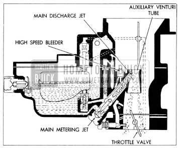
1956 Buick Main Metering System
The main discharge nozzle is designed so that if any vapor bubbles are formed in the hot gasoline, the vapors will follow the outside channel around the main discharge nozzle instead of passing through the jet tube. These vapor bubbles escape through the dome-shaped high speed bleeder and thereby reduce percolating troubles.
Operation of Stromberg Power System
For maximum power at any speed or for all operation above approximately 75 MPH a richer mixture is required than that necessary for normal throttle opening. The richer mixture is supplied through the main metering systems of both barrels of 1956 Buick Stromberg 2-barrel Carburetor by means of the power system.
The power piston cylinder is connected by a channel to the intake manifold. At part throttle position the manifold vacuum is sufficient to hold the power piston in its “up” position against the tension of the piston spring. When the throttle valve is opened to a point where additional fuel is required for satisfactory operation and the manifold vacuum drops to approximately 4 to 6 inches, the piston spring moves the power piston down to open the power by-pass jet. Opening of the by-pass jet allows additional metered fuel to enter the main discharge jets through a by-pass channel without passing through the restricted main metering jet. See figure 3-59.
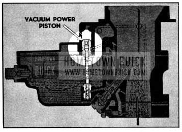
1956 Buick Carburetor Power System
Operation of Stromberg Accelerating System
For smooth and rapid acceleration it is necessary to supply an extra quantity of fuel momentarily when the throttle is suddenly opened. This is accomplished by operation of the accelerating pump piston which is directly connected to the throttle valve lever by means of a rod and pump lever. See figure 3-60.
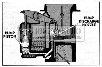
1956 Buick Carburetor Accelerating System
When the throttle is closed, the pump piston moves up and draws a supply of fuel from the float chamber through the inlet ball check into the pump cylinder. When the throttle valve is opened, the piston on its downward stroke exerts pressure on the fuel which closes the inlet ball check, opens the outlet ball check, and discharges a metered quantity of fuel through the pump discharge nozzles in each barrel of 1956 Buick Stromberg 2-barrel Carburetor. This occurs only momentarily during the accelerating period. The pump duration spring provides a follow-up action so that the fuel discharge carries out over a brief period of time.
When the throttle is held in fixed position, the pressure on the fuel in the pump cylinder decreases sufficiently so that the outlet check valve closes and fuel ceases to discharge from the pump nozzles. With the throttle held in a fixed position the fuel flows only through the idle or main metering systems as previously described.
Operation of Stromberg Automatic Choke
The automatic choke housing in the Series WW carburetor is built into the throttle body. The choke control is of the mechanical type having no vacuum piston.
The choke consists of an offset choke valve mounted on a shaft in the air horn connected through a link to a start-aid and choke unloader plate on one side of the 1956 Buick Stromberg 2-barrel Carburetor. On the other side, the choke valve is connected through a rod to a shaft in the choke housing. The choke valve has a slight bend forward at the upper edge to eliminate the tendency of choke valve to partially close at high speeds. See figure 3-61.
1956 Buick Automatic Choke Housing Parts
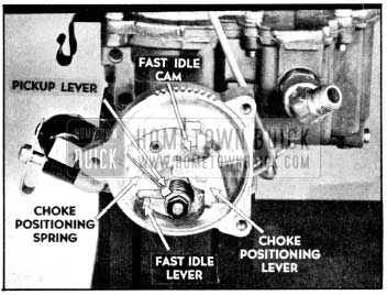
In the choke housing there is a fast idle cam, a thermostat spring, and a choke positioning spring. The fast idle cam operates in conjunction with the choke to provide enough throttle opening to prevent stalling during the warm-up period. The thermostat spring determines the position of the choke valve and the fast idle cam during the warm-up period for most throttle positions. However, when the throttle is near its closed position, the choke positioning spring overcomes any thermostat spring tension and causes the choke valve to partially open. See figure 3-61.
When the throttle is opened far enough to engage the starter switch, the choke positioning_ spring has no effect on choke valve position. During engine starting, then, choke position is determined entirely by the thermostat spring.
Operation of Stromberg Choke Unloader
If the engine becomes flooded for any reason, the choke valve can be partially opened by depressing the accelerator to the full extent of its travel. This causes an arm on the throttle lever to contact and rotate the choke unloader plate. This pulls down on a link and forces the choke valve partially open. See figure 3-69.
Because the choke will partially open or “unload” when the accelerator pedal is fully depressed, the pedal should only be depressed when making a cold start just far enough to engage the starter switch. However, the 1956 Buick Stromberg 2-barrel Carburetor does have a start-aid to help prevent unintentional choke unloading; it consists of a torsion spring which winds up when it contacts the unloader plate and provides resistance to further throttle opening, when the choke is closed. Additional throttle opening causes a “snap-through” of the spring which notifies the driver that the choke is unloaded.
3-24 ADJUSTMENT OF FAST IDLE, LOW SPEED CHOKE POSITIONING, AND CHOKE UNLOADER.
If cold engine idles too fast or too slow, runs too rich or too lean at idle and low speeds, or if choke unloader does not operate properly, check all of the following adjustments in order:
- Remove air cleaner. Remove thermostat cover. Remove throttle stop screw and spring; replace screw without spring.
- Hold throttle valves fully closed and turn throttle stop screw in just to point of contact with throttle lever. Then turn stop screw in 5 turns.
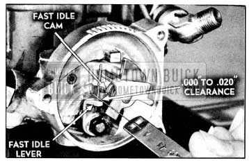
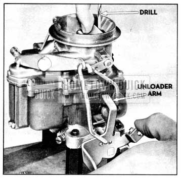
- With choke valve closed and throttle lever held against stop screw, measure clearance between fast idle lever and high step of fast idle cam using a No. 55 drill. See figure 3-62, (View A).
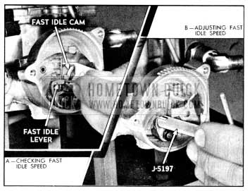
1956 Buick Fast Idle Speed Adjustment
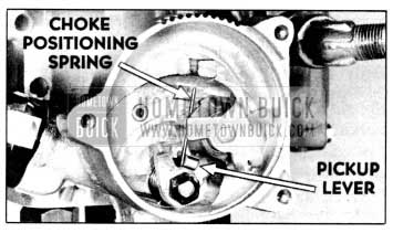
1956 Buick Choke Spring Pick-Up Lever Adjustment
1956 Buick Checking Fast Idle Cam Adjustment
If clearance is not correct, bend choke rod as required to obtain correct clearance using Tool J-5197. See figure 3-65.
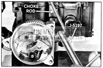
1956 Buick Adjusting Fast Idle Cam
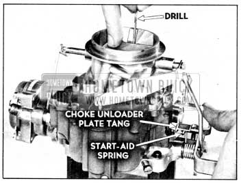
1956 Buick Checking Start Aid Adjustment
Bend unloader link to obtain proper setting using Tool J-5197. See figure 3-67.
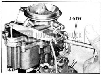
1956 Buick Adjusting Start Aid
1956 Buick Checking Carburetor Choke Unloader Adjustment
If clearance is not as specified, correct by bending unloader arm on throttle lever. See figure 3-69.
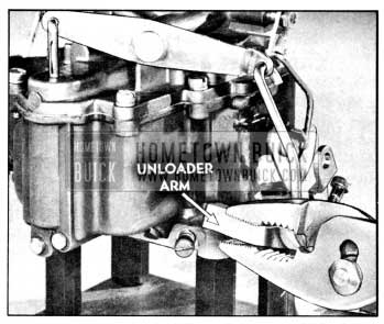
1956 Buick Adjusting Choke Unloader
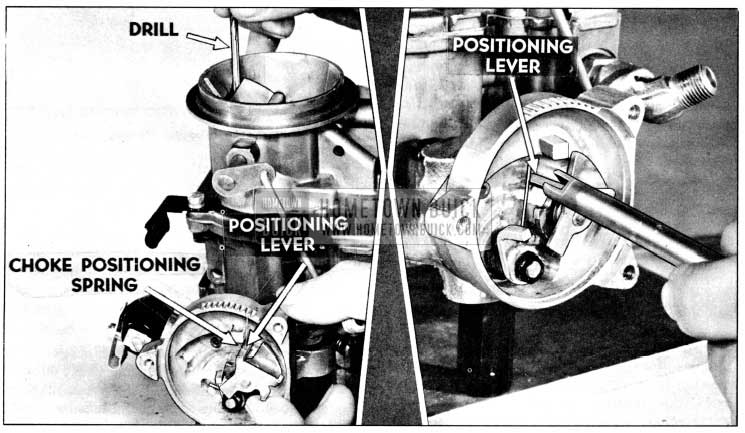
1956 Buick Choke Positioning Lever Adjustment
3-25 DISASSEMBLY, CLEANING, INSPECTION OF 1956 BUICK STROMBERG 2-BARREL CARBURETOR
Disassembly of 1956 Buick Stromberg 2-barrel Carburetor
- Place 1956 Buick Stromberg 2-barrel Carburetor on a suitable mounting fixture such as J-5923. Remove choke rod cotter pin and choke rod.
- Remove choke unloader link hair-pin clip, washer, and unloader link. Remove unloader arm nut using Wrench T-25047 (5/16 hex.); then remove lock washer and unloader arm.
- File off staked ends of choke valve screws. Then remove screws, choke valve, and shaft. Note: Choke valve is manufactured with a slight bend; do not straighten valve.
- Remove pump rod cotter pin and pump rod. Remove pump plunger cotter pin.
- Remove air horn screws, air horn, and gasket. Remove pump plunger assembly and washer from air horn.
- Remove power piston assembly from air horn by pushing spring down and applying pliers to outer end of piston stem. Then, using a 1″ wood block as a fulcrum for pliers, pull piston straight up to avoid bending stem.
- Remove pump nozzle with screw, washer, and gasket. Remove idle jet tubes.
- Remove float needle seat and elbow fitting together with gasket and float needle. Remove float retainer, float, and hinge pin. See figure 3-71.
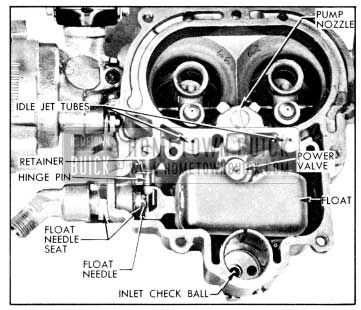
1956 Buick Main Stromberg Carburetor Body Parts
1956 Buick Removing Main Metering Well Parts
Cleaning 1956 Buick Stromberg 2-barrel Carburetor Parts
Regardless of the number of new parts that are used in rebuilding a 1956 Buick Stromberg 2-barrel Carburetor, the job in the end will not be satisfactory unless all metal parts are thoroughly cleaned. Because of the nature of 1956 Buick Stromberg 2-barrel Carburetor parts, with numerous small passages subject to fouling with tenacious carbon and gum deposits, ordinary cleaning processes are entirely inadequate. The correct procedure is to use a cleaning bath in which metal parts can be immersed and “soaked” for sufficient time after disassembly to thoroughly clean all surfaces and channels.
Bendix Metalclene has been developed especially for cleaning carburetors, and is recommended for this purpose. Regardless of the cleaning material used, however, be sure to thoroughly rinse the parts in kerosene, distillate, or white gasoline to remove all gummy deposits that have been softened by the cleaner.
If the passages in main body appear to be heavily fouled with carbon or gum it is advisable to remove the lead ball plugs so that the cleaning solvent can penetrate and wash through the channels. Lead ball plugs may be removed with Plug Remover T-25052, using care not to damage the plug seats in body. Install new ball plugs after cleaning is completed, using Plug Set T-25054 to swage plug into its seat.
Inspection of 1956 Buick Stromberg 2-barrel Carburetor Parts
After cleaning, all parts should be carefully inspected for wear or damage as follows:
- Air Horn and Choke Parts. Check clearance of choke stem in bearings of air horn. If stem or bearings are worn so that excessive clearance exists, replace the worn parts. Make sure that bearings are free of gum.
If thermostat is distorted or damaged it must be replaced with a new thermostat cover with thermostat assembly. The thermostat is not furnished separately because the index mark is stamped on cover after installation of thermostat, to insure proper calibration.
- Float Needle Valve and Seat. Because of the wear that normally occurs in these parts and the necessity of having a tight seating valve, it is advisable to replace these parts if the 1956 Buick Stromberg 2-barrel Carburetor has been used for considerable mileage. Even if mileage is low, replace these parts if needle is grooved or seat is damaged.
- Vacuum Power Piston and By-Pass Jet. Make certain that the surface of the piston is thoroughly clean. Do not use any abrasive material for polishing the piston surface. Inspect for wear or damage. Replace if necessary. Test by-pass jet for tight seating by sucking on the upper end. Replace jet if doubtful.
- Main Body. Make certain the main body is thoroughly clean and that all passages are free of foreign material. Check high speed and idle air bleeders for correct sizes, using a drill shank as a gauge. For drill sizes see Stromberg Carburetor Calibrations, Paragraph 3-1.
- Main Discharge Jets and Idle Tubes. Inspect tips of main discharge jets to make certain that they are not damaged, and that walls are not distorted so as to deform the holes. Test idle tubes by blowing or sucking to make sure that metering holes are clear. Inspect small ends to make sure that they are not damaged so as to deform the metering holes.
Replace any parts whose condition appears doubtful.
- Pump Piston, Discharge Nozzle and Related Parts. Inspect pump piston leather washer for cracks, creases, turned edges, or other damage.
Test discharge nozzle by sucking or blowing to make sure that all holes are clear. It is advisable to replace pump inlet and discharge channel check valve balls since these parts are small and difficult to inspect.
Inspect check valve ball seats in main body with a good light. If a seat appears rough, place ball in seat and tap lightly to swage a good seat, then discard the ball.
- Throttle Valve Body and Idle Needle Valves. Be sure that the idle discharge holes, the air bleeders, and the barrels of the throttle valve body are clean of all carbon deposits. A comparatively small amount of carbon in barrel may have the effect of decreasing the bore sufficiently to prevent the throttle valves resting at the correct angle when closed. This can have serious effects on performance because the distance from the throttle valve, when closed, to the edge of the idle discharge hole must be kept within close limits to the established dimension.
Check the size of the upper idle discharge hole by inserting the shank of the correct size drill. This has the further advantage of removing any foreign matter that may be obstructing the hole. The lower discharge hole for the idle needle valve should be checked in the same manner. For drill sizes see Stromberg Carburetor Calibrations (par. 3-1).
Make sure that the No. 36 drill holes in the rear side of throttle body are clear. These holes permit vapors to escape rather than rising into the air cleaner when the engine is stopped.
Inspect idle need les for scoring or other damage. If ends of idle needles are grooved or bent, replace the valves.
Check wear of throttle stem bearing. There should not be more than about .006″ play, otherwise air leaks will interfere with performance.
- Throttle Valve s, Throttle Lever and Stem Assembly. See that throttle valves are not bent and do not have burrs or sharp edges. Replace if damaged.
Inspect throttle lever and stem assembly for wear on bearing surfaces. Check pump’ rod holes for wear and also see that lever is not loose on stem. Replace if necessary.
- Accelerator Vacuum Switch. Clean and inspect parts of accelerator vacuum switch as specified in paragraph 10-30.
3-26 ASSEMBLY AND ADJUSTMENT OF 1956 BUICK STROMBERG 2-BARREL CARBURETOR
When assembling the 1956 Buick Stromberg 2-barrel Carburetor use all new gaskets and any additional new parts found to be necessary during inspection. Calibrated parts must be as specified for carburetor CODE numbers which is stamped on the air horn near the fuel inlet.
- Place throttle body assembly on mounting fixture. Install throttle stop screw and spring. Hold throttle valves fully closed and turn throttle stop screw in just to the point of contact with throttle lever. Then turn screw in one turn for an initial idle speed setting. Install idle needles and springs. Seat idle needles lightly, then back each needle out 1 3/4 turns from seat for initial mixture setting. Do not force need le against its seat as this will score it and ruin it for service.
- Install fast idle cam, spacer washer, choke housing shaft and lever assembly arm, lock washer, and nut.
- Install starter switch ball, plunger, guide block assembly, return spring, terminal cap, clip, and screw as specified in paragraph 10-30.
- Place new gasket on inverted main body and install throttle body with two large diameter screws to the center and two longest small diameter screws to the outside.
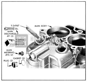
- Install main discharge nozzles using Remover T-24967. Be careful to position nozzles so that fiat surface is parallel with direction of air flow.
- Install main metering jets using Wrench T-24924. Install main metering well plugs using new copper gaskets if available; otherwise, make sure that plugs and seats are clean to insure tight joint. Tighten plugs with Tool T-19099. See figure 3-72.
- Place 1956 Buick Stromberg 2-barrel Carburetor on mounting fixture. Install power valve with new gasket.
- Install float and hinge pin. Install float retainer clip using needle-nose pliers. Install float needle seat and elbow fitting together with ga8ket and float needle.
- Hold float arm tang against float needle; then check float level using Gauge J-5475. See figure 3-73. If top of float is not specified distance (5/16″) below top edge of float bowl, adjust by bending float arm tang. Be sure float is centered so it does not rub walls of bowl.
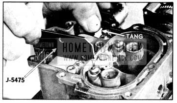
1956 Buick Float Level Adjustment

1956 Buick Accelerator Pump Adjustment
Leave A Comment
You must be logged in to post a comment.