SECTION 13-C 1956 BUICK WINDSHIELD WIPERS, AND UPPER INSTRUMENT PANEL
13-10 1956 BUICK WINDSHIELD WIPERS
Description of 1956 Buick Windshield Wipers
All series windshield wiper motors are mounted on an auxiliary drive which is attached to the front face of the cowl panel under the hood. The motor drives a short shaft in the auxiliary drive which extends through the cowl panel. Pulleys on the rear end of the auxiliary shaft actuate the wiper transmissions through cables attached to the pulleys. Each wiper transmission is equipped with spring loaded pulleys which act as a cable tensioning device. The end of the transmission shaft, when depressed, releases the spring tensioning device, allowing the pulleys to rotate and tension the cables. When the shaft is released, the pulleys are locked in relation to each other.
Removal and Replacement – 1956 Buick Windshield Wiper Motor
- Remove two screws attaching wiper motor to auxiliary drive.
- Disconnect hoses and wiper control cable.
- To install reverse procedure.
Removal and Replacement – 1956 Buick Windshield Wiper Auxiliary Drive
- Remove instrument panel upper section. (See par. 13-11.)
- Adjust wiper cables to slack position. (See step 3 under supbar. d below.)
- Observe attachment of transmission cables at auxiliary drive pulleys to insure proper installation. Then disconnect cables from auxiliary drive pulleys.
- Remove two screws attaching auxiliary drive to shroud panel.
- To install, check gasket around opening in shroud panel and install auxiliary drive assembly to cowl panel.
- Install transmission cables to auxiliary drive assembly.
- Tension cables by depressing end of transmission shaft.
- Operate motor and check operation of entire wiper mechanism.
- Install upper section of instrument panel.
Removal and Replacement – 1956 Buick Windshield Wiper Transmission
NOTE: Some jobs are equipped with a Cam-O-Matic windshield wiper transmission which has a windshield wiper arm cam on the transmission shaft.
A follower on the wiper arm engages with the cam maintaining blade to glass contact. The wiper cam is secured to the transmission shaft by the transmission spanner nut.
- Remove wiper blade and arm assembly. NOTE: On Cam-0-Matic transmission, remove wiper arm assembly by raising the upper section of the wiper arm to disengage the cam follower from the cam. With wiper arm in raised position, carefully pull or pry arm from transmission shaft.
- Remove upper section of instrument panel. (See par. 13-11.)
- Adjust cables to slack position by depressing transmission shaft to unlock pulleys while helper pulls cable to obtain slack. When sufficient slack is obtained, release transmission shaft to lock pulleys in slack position.
- Observe attachment of transmission cables at auxiliary drive pulleys to assure proper installation. Then disconnect cables from auxiliary drive pulleys. See figure 13-16.
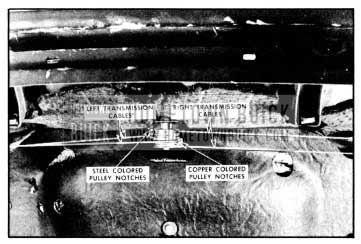
1956 Buick Cable Attachment to Auxiliary Drive
- Remove transmission spanner nut, transmission escutcheon, cam and reveal moulding clip.
- Loosen defroster horns and move back far enough to allow access to transmission support.
- Remove transmission support which is retained by two bolts.
- Remove rubber gasket and gasket retainer plate nuts; disconnect windshield washer hose and carefully pull transmission down through cowl panel and remove from body.
- To install, reverse the procedure.
- To restore tension in cables after installation, push in on end of transmission shaft.
13-11 1956 BUICK INSTRUMENT PANEL UPPER SECTION
Removal of Instrument Panel Upper Section
- Remove side and lower windshield garnish mouldings.
- Remove upper instrument panel bolts and washers around the base of the 1956 Buick windshield.
- Remove flat-head finishing screws at lower flange of upper section of the instrument panel.
- Remove screw and finishing cap at each end of instrument panel.
- Carefully remove upper section of instrument panel.
Removal of 1956 Buick Instrument Panel Cover
- If necessary to remove instrument panel cover, after the upper section is removed: Remove finishing moulding lower front edge of upper section by straightening moulding attaching tabs located along inner side panel.
- Detach cemented sections of front and rear edges of cover and remove cover from panel. Unless required, do not remove white wadding or rubber pad from panel.
Replacement of 1956 Buick Instrument Panel Cover
- To replace 1956 Buick instrument panel cover, clean and dry cover cementing surfaces on panel.
- Position cover trim material on panel, aligning seams at outer ends of cover with the contour of panel.
- Apply trim cement to front and rear edges of cover and to cementing surfaces on panel. Allow cement to become “tacky.”
- Remove “fullness” and “draws” from cover material and press cemented surfaces of cover to panel firmly to obtain a good bond.
- Carefully slit openings at lower edge of cover for insertion of finishing moulding attaching tabs.
- Insert finishing moulding tabs into slots in instrument panel and twist tabs at inner side of upper instrument panel to secure mouldings.
- Clean off excess cement and install instrument panel upper section to lower section, and all parts previously removed.
Leave A Comment
You must be logged in to post a comment.