SECTION 2-D 1956 BUICK CYLINDER HEAD AND VALVE MECHANISM SERVICE
2-14 1956 BUICK CYLINDER HEAD AND VALVE SERVICE
Removal of 1956 Buick Cylinder Head
- Drain the radiator and cylinder block.
- Remove air cleaner and silencer, then disconnect all pipes from carburetor and intake manifold.
- Disconnect wires from accelerator vacuum switch, remove coil, remove throttle return spring, disconnect equalizer shaft bracket from engine.
- Remove intake manifold and carburetor as an assembly. Remove manifold gaskets.
- When removing RIGHT cylinder head; (1) remove oil gauge rod, (2) disconnect Dynaflow filler pipe bracket from head, (3) remove generator mounting bracket, (4) remove air conditioning compressor, if present.
When removing LEFT cylinder head; (1) disconnect temperature gauge tube, (2) remove power steering gear pump with mounting bracket, if present, and move it out of the way with hoses attached.
- Remove spark plug cover and disconnect wires from spark plugs.
- Disconnect water manifold from both 1956 Buick cylinder heads and disconnect exhaust manifold from head to be removed.
- With air hose and cloths, clean dirt off 1956 Buick cylinder head and adjacent area to avoid getting dirt into engine. It is extremely important to avoid getting dirt into the hydraulic valve lifters.
- Remove rocker arm cover and remove rocker arm and shaft assembly from 1956 Buick cylinder head. Lift out push rods.
- Slightly loosen all cylinder head bolts then remove bolts and lift off the cylinder head. Remove gasket.
- With 1956 Buick cylinder head on bench, remove all spark plugs for cleaning and to avoid damage during work on the head.
Reconditioning Valves and Guides
- Place 1956 Buick cylinder head on Holding Fixture J 5251 with valve springs straight up. Compress valve springs with fixture lever and remove the spring cap keys, then remove the springs and caps. See figure 2-15.
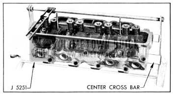
1956 Buick Removing Valve in Holding Fixtures J 5251
- Carefully roll 1956 Buick cylinder head away from holding fixture until one edge rests on bench, then remove valves. Place valves in a stick with numbered holes to keep them in order for reinstallation in original positions.
- Scrape all carbon from combustion chambers, piston heads, and valves. Clean all carbon and gum deposits from valve guide bores. When using scrapers or wire brushes for removing carbon, avoid scratching valve seats and valve faces.
- Inspect valve faces and seats for pits, burned spots or other evidences of poor seating. If a valve head must be ground until the outer edge is sharp in order to true up the face, discard the valve because the sharp edge will run too hot.
- Check fit of valve stems in guides. If clearance is excessive replace the guides, as follows:
- Remove center cross bar from Holding Fixture J 5251, place 1956 Buick cylinder head in fixture so that inlet port side rests against the fixture lower bar, then drive guides out from combustion chamber side using Driver J 269. See figure 2-16.
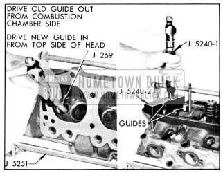
1956 Buick Removing and Installing Valve Guide
Replacement of 1956 Buick Rocker Arms
- Remove cotter pin, flat washer and spring washer from each end of the rocker arm shaft and remove bolts from brackets. Remove rocker arms, brackets and springs from shaft.
- Clean and inspect all parts and replace those that are excessively worn.
- Assemble springs, rocker arms and brackets on shaft as shown in figure 2-17.
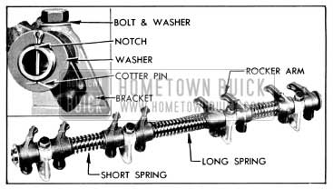
1956 Buick Rocker Arm and Shaft Assembly
Note that the long spring is at middle of shaft, the valve ends of all rocker arms slant toward middle of shaft, and a bracket is located between each pair of rocker arms.
Installation of 1956 Buick Cylinder Head
Make certain that gasket surfaces and all parts are absolutely clean, then install 1956 Buick cylinder head by reversing the procedure for removal, paying particular attention to the following points.
- When handling thin crimped steel gaskets use care to prevent damage to the lacquered surface coat and to prevent kinking at sealing rings stamped in gasket. The lacquered gasket should not be coated with any type of sealing material when installed. Always use a new steel gasket because the stamped sealing rings are flattened in a used gasket.
- Right and left cylinder heads are identical except that the water inlet port is open at front end and is plugged at rear end as installed on engine.
- After installation of 1956 Buick cylinder head, tighten all bolts a little at a time about three times around in sequence shown in figure 2-18, then finally tighten in same sequence to 63-73 ft. lbs. torque.
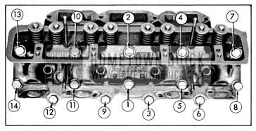
1956 Buick Cylinder Head Bolt Tightening Sequence
Always use an accurate torque wrench when tightening 1956 Buick cylinder head bolts, to insure uniform and proper torque on all bolts. Uneven or excessively tightened bolts may distort cylinder bores, causing compression loss and excessive oil consumption.
2-15 1956 BUICK HYDRAULIC VALVE LIFTER SERVICE
Removal of 1956 Buick Valve Lifters
- Remove 1956 Buick air cleaner and silencer, then disconnect all pipes from carburetor and intake manifold.
- Disconnect wires from the accelerator vacuum switch and remove the throttle return spring. Remove ignition coil and equalizer shaft bracket from intake manifold and move these parts out of the way.
- Remove intake manifold and carburetor as an assembly. Remove manifold gaskets.
- With air hose and cloths, clean dirt from 1956 Buick cylinder heads, valve lifter cover and adjacent area to avoid getting dirt into engine. It is extremely important to avoid getting dirt into the hydraulic valve lifters.
- Remove rocker arm cover, rocker arm and shaft assembly, and push rods from bank where valve lifters are to be removed.
- Remove 1956 Buick valve lifter cover and remove the valve lifters that require service. Place lifters in a wooden block having numbered holes or use other suitable method of identifying them according to original position in engine.
If less than a full set of lifters is being removed, immediately disassemble and inspect one or two for presence of dirt or varnish (subpar. c). If lifters contain dirt or varnish it is advisable to remove all lifters for cleaning and inspection; otherwise it will be satisfactory to service only those lifters that are not operating properly.
- Examine the cam contact surface at lower end of each lifter body. If this surface is excessively worn, galled, or otherwise damaged discard the lifter assembly. In this case also examine the mating camshaft lobe for excessive wear or damage.
Cleaning Tank J 5093 and Cleaning Fluids
Cleaning Tank J 5093 is designed to permit a systematic and thorough cleaning of hydraulic valve lifter parts. It provides three compartments for cleaning fluids, two 16-compartment cleaning trays, one small tray for special tools and a removable cover. The two cleaning trays allow one set of lifters to be soaking while another set is being worked on. The cover, placed on bench in front of tank, provides an easily cleaned working surface. See figure 2-19.
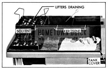
1956 Buick Tank J 5093 Set Up for Cleaning Lifter Parts
The left hand compartment of tank is for cleaning sol vent in which parts are soaked after disassembly. The solvent required should either dissolve the varnish deposit on lifter parts or soften the varnish so that it can be removed by wiping, after soaking for not longer than one hour. Gulf Motor Flush, or an equivalent solvent, will effectively clean lifter parts.
When selecting a cleaning solvent, careful consideration should be given to its effect upon the hands. The directions and safety precautions of the manufacturer should be understood and observed to avoid personal injury. A wise safety rule is to wear rubber gloves when handling parts that are wet with cleaning solvent.
The middle compartment of tank is for clean kerosene to be used for cleaning parts after removal from the cleaning solvent. The right hand compartment is for clean kerosene to be used exclusively for final rinsing of parts just before assembly.
When the cleaning tank is not being used the cover should be installed to exclude dirt from the cleaning fluids. As a further precaution, do not use the tank for any parts except hydraulic valve lifters.
To avoid early contamination and deterioration of the cleaning solvent a separate pan of suitable size should be provided so that a tray of lifter parts can be flushed in kerosene before it is placed in the solvent.
Disassembly and Cleaning of Lifters
- Disassemble each valve lifter by using a push rod to hold down the push rod seat while removing the plunger retainer from the lifter body, using Retainer Remover J 5238. See figure 2-20, View A. Remove push rod seat and plunger from lifter body.
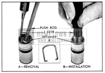
1956 Buick Removing and Installing Plunger Retainer
If a plunger sticks in lifter body place lifter in large end of Plunger Remover J 4160-A, with plunger inward. While holding lifter with thumb, rap the open end of remover against a block of wood with just enough force to jar the plunger from body. See figure 2-21.
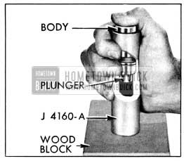
1956 Buick Removing Stuck Plunger with J 4160-A
- Drain oil out of body into a waste can and then remove the ball, retainer and spring. A strainer placed over waste can will prevent dropping these parts into can.
- Place all parts of each lifter in a separate compartment of a tray from Cleaning Tank J 5093. The body and plunger are selectively fitted to each other and must not be interchanged with parts of other lifters. Keeping all parts of the lifter together until cleaned and inspected will aid in diagnosing cause of improper operation.
- Rinse the tray full of lifter parts in a pan of kerosene to remove as much oil as possible. This will reduce contamination of the cleaning solvent and extend its effective life.
- Submerge the tray and parts in the cleaning solvent in left hand compartment of Cleaning Tank J 5093 and leave to soak for approximately one hour. The time required will depend on the varnish on lifter parts and the effectiveness of the solvent.
- After the varnish has dissolved or has softened sufficiently to permit removal by wiping, raise the tray and suspend it above the solvent by means of the hooks on tray handles. Allow tray and parts to drain so that solvent will be saved.
- Rinse the tray of parts in the pan of kerosene to cut the solvent and avoid injury to hands, then place tray on the tank cover located on bench in front of cleaning tank.
- Working on one lifter at a time and using CLEAN lint-free cloths, thoroughly wipe off all parts. Clean the plunger and the external and internal surfaces of the body with a hard wiping action to remove any varnish deposits. Rinse the parts in the kerosene contained in the middle compartment of cleaning tank, using Cleaning Brush J 5099 in the bore of lifter body.
NOTE: To insure absolute cleanliness of a reconditioned lifter assembly, it is advisable to inspect and assemble each (lifter subpar. d, e, f) before cleaning the next lifter.
Inspection of 1956 Buick Hydraulic Lifter Parts
- Lifter Body. Inspect inner and outer surfaces of body for blow holes and scoring. Replace lifter assembly if body is roughly scored or grooved, or has a blow hole extending through the wall in position to permit oil leakage from lower chamber. The prominent wear pattern just above lower end of body should not be considered a defect unless it is definitely grooved or scored; it is caused by side thrust of cam against body while the lifter is moving vertically in its guide.
Inspect the cam contact surface on lower end of lifter body. Replace the lifter assembly if this surface is excessively worn, galled, or otherwise damaged. A lifter body that has been rotating will have a round wear pattern and a non-rotating lifter body will have a square wear pattern with a very slight depression near the center. Either condition is normal and such bodies may be continued in use if the surface is free of defects. See figure 2-22.
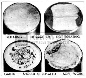
1956 Buick Lifter Body Wear Patterns
A blackened appearance is not a defective condition. Sometimes the discoloration serves to highlight slight grinder chatter marks and give the outer surface of plunger a ridged or fluted appearance. This condition will not cause improper operation, therefore it may be disregarded.
Check Ball Travel
Correct check ball travel is very important. Too much ball travel would allow excessive flow of oil from the lifter lower chamber before the ball could seat, resulting in excessive lash in the valve linkage. Insufficient ball travel would cause the volume of oil in the lower chamber to increase, resulting in “pump-up” which would prevent the engine valve from seating.
However, tests show that any ball retainer now used will hold ball travel within satisfactory limits unless the retainer is badly worn or damaged. Therefore, it is not necessary to measure travel of the check ball.
Assembly of 1956 Buick Hydraulic Lifters
All parts must be absolutely clean when a hydraulic lifter is assembled. Lint and dust may adhere to the parts if they are blown off or wiped with cloths; therefore they should be rinsed in CLEAN kerosene and assembled without drying.
- Rinse lifter plunger in the kerosene in middle compartment of cleaning tank and then give it a thorough final rinsing in the kerosene in right compartment.
- Hold plunger in vertical position with feed hole up, then rinse and install the check ball, ball retainer, spring, and body over the plunger. See parts in figure 2-23.
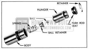
1956 Buick Hydraulic Valve Lifter Parts
Testing Lifter Leakdown Rate
After a hydraulic lifter has been cleaned, inspected, checked for ball travel, and assembled it must be tested before it is installed in an engine. Lifter Test Fixture J 5095 has been designed to test the leakdown rate of a lifter to determine whether it is within limits which assure satisfactory lifter operation.
The following procedure must be carefully followed to obtain an accurate test.
- Thoroughly clean the cup of test fixture, install cup on fixture, and fill it to within 1/2″ of the top with “Hydraulic Lifter Test Fluid,” which is available through Kent-Moore Organization, Inc., under KM number J 5268.
- Remove rubber washer (used for larger lifters) and install Gauge Sleeve J 5180-5 in the cup; also install Buick V-8 Gauge Rod Nose J 5181-2 in the ram.
- Swing the weight arm up out of the way, raise the ram and place the valve lifter (top side up) in sleeve J 5180-5. The lifter must be completely covered by the fluid during test.
- Lower the ram to rest in the lifter push rod seat, then lower the weight arm to rest on the roller of ram as shown in figure 2-24.
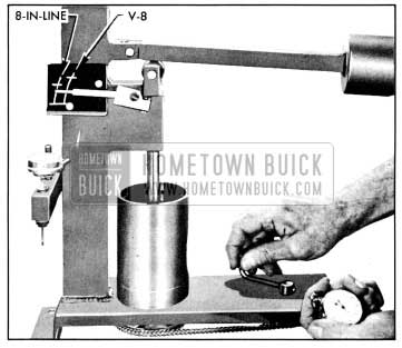
1956 Buick Checking Leakdown Rate
Finally, pump vigorously for approximately 10 additional strokes to make sure all air is removed from the lifter. NOTE: If one stroke offers noticeable weak resistance during the last 10 pumping strokes replace the check ball in lifter and repeat the leak down test to this point.
- Raise weight arm to allow the lifter plunger to come up to its retainer, then lower the arm to rest on the ram roller. As the pointer starts moving upward start rotating the fluid cup by turning the handle one revolution every two seconds. See figure 2-24.
- Use a stop watch to check the time required for the pointer to move from the lower to the upper mark on scale where marked “BUICK V-8.” The cup must be rotated during this test. See figure 2-24.
- The leakdown rate (time between marks) must be between 12 and 40 seconds to assure satisfactory lifter performance. A doubtful lifter should be tested three or four times. Replace any lifter which does not test within the specified limits.
- After all lifters have been tested, place the cover over the test fixture to keep dirt out of the cup and fluid. The fluid should be discarded and the cup should be thoroughly cleaned after a few sets of lifters have been tested.
Installation of Valve Lifters
Make certain that valve lifter guide holes and adjacent area of cylinder block are clean, then oil and install valve lifters. Each lifter must slide freely in its guide hole; if a lifter is tight in one guide hole fit it to another hole.
Complete the installation of all parts by reversing the procedure for removal. An initial adjustment for clearance is not required, therefore, the valve train does not have any provision for adjustment after assembly.
2-16 1956 BUICK TIMING CHAIN, COVER, AND CAMSHAFT SERVICE
Remove and Install 1956 Buick Timing Chain
- Drain engine cooling system, then remove radiator core, shroud, fan belt, fan and pulley, and crankshaft balancer.
- Remove all bolts that attach the timing chain cover and the water manifold to the upper and lower crankcase and the 1956 Buick cylinder heads. Do not remove five small bolts attaching water pump to chain cover. Remove cover and manifold, using care to avoid damaging lower crankcase (oil pan) gasket.
- Remove oil slinger from crankshaft and remove the bolt, lockwasher and plain washer that attaches the fuel pump operating eccentric and the camshaft sprocket to front end of camshaft.
- If there has been doubt about the valve timing, turn crankshaft until the camshaft sprocket keyway is straight down toward the crankshaft and the “0” timing marks on both sprockets are toward left side of engine. If timing chain is installed to provide correct valve timing, there will be 12 teeth between the “0” timing marks, including teeth aligned with the marks. See figure 2-25.
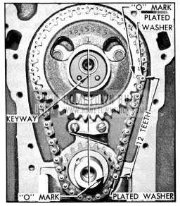
1956 Buick Timing Chain and Sprockets Properly Installed
Replacement of 1956 Buick Crankshaft Oil Seal in Timing Chain Cover
- With timing chain cover on bench, remove the braided fabric packing with a screwdriver and then tap the pressed steel shedder out of the cover.
- Work new packing into the shedder, then drive shedder into recess in timing chain cover, using Installer J 5250-1. See figure 2-26, view A.
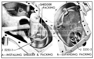
1956 Buick Installing Crankshaft Oil Seal
1956 Buick Camshaft Bearings and End Play
The five steel-backed babbitt-lined camshaft bearings are pressed into the crankcase. Going from front to rear, each bearing is bored .030″ smaller than the preceding bearing, and each camshaft journal is correspondingly reduced in diameter.
The 1956 Buick camshaft bearings must be line reamed to size after being pressed into the crankcase. Since this operation requires special reaming equipment the original bearings should be retained unless severely damaged. Slightly scored camshaft bearings will be satisfactory if the surface of camshaft journals are polished and bearings are cleaned up to remove burrs, and the fit of shaft in bearings is free and within the clearance limits of .0015″ to .004″.
Camshaft end play is controlled by a spacing ring located between the camshaft front bearing journal and a thrust plate attached to crankcase behind the camshaft sprocket. The spacing ring provides clearance or end play of .004″ to .008″ when the camshaft sprocket is tightened against it by the sprocket bolt.
IMPORTANT: All 1956 Dynaflow camshafts may be identified by two grooves cut into the land just forward of the number three bearing journal. The se camshafts are not interchangeable with those in synchromesh equipped cars which have no grooves.
SECTION 2-E REPLACEMENT OF 1956 BUICK CRANKSHAFT AND CONNECTING ROD BEARINGS, PISTONS AND RINGS
2-17 REPLACEMENT OF CONNECTING ROD BEARINGS
A connecting rod bearing consists of two halves or shells which are alike and interchangeable in rod and cap. When the shells are placed in rod and cap the ends extend slightly beyond the parting surfaces so that when rod bolts are tightened the shells will be clamped tightly in place to insure positive seating and to prevent turning. The ends of shells must never be filed flush with parting surface of rod or cap.
If a precision type connecting rod bearing becomes noisy or is worn so that clearance on crankpin is excessive, a new bearing of proper size must be selected and installed since no provision is made for adjustment. Under no circumstances should the connecting rod or cap be filed to adjust the bearing clearance.
Inspection of 1956 Buick Connecting Rod Bearings and Crankpin Journals
After removal of lower crankcase, disconnect two connecting rods at a time from crankshaft and inspect the bearings and crankpin journals. While turning crankshaft it is necessary to temporarily re-connect the rods to crankshaft to avoid possibility of damaging the journals through contact with loose rods.
If 1956 Buick connecting rod bearings are chipped or scored they should be replaced. If bearings are in good physical condition check for proper clearance on crankpins as described in subparagraph b, below.
If crankpin journals are scored or ridged the crankshaft must be replaced, or reground for undersize bearings, to insure satisfactory life of connecting rod bearings. Slight roughness may be polished out with fine grit polishing cloth thoroughly wetted with engine oil. Burrs may be honed off with a fine oil stone.
Use an outside micrometer to check crankpins for out-of-round. If crankpins are more than .0015″ out-of-round, satisfactory life of new bearings cannot be expected.
Checking Clearance and Selecting Replacement Bearings
Service bearings are furnished in standard size and several undersizes (including undersizes for reground crankpins).
The clearance of connecting rod (and crankshaft) bearings may be checked by use of Plastigage, Type PG-1 (green), which has a range of .001″ to .003″. Plastigage is manufactured by Perfect Circle Corporation, Hagerstown, Indiana, and is available through Buick parts warehouses under Group 0.093.
- Remove connecting rod cap with bearing shell. Wipe oil from bearing and crankpin journal, also blow oil out of hole in crankshaft. NOTE: Plastigage is soluble in oil.
- Place a piece of Plastigage lengthwise along the bottom center of the lower bearing shell (fig. 2-27, view A), then install cap with shell and tighten bolt nuts to 40-45 ft. lbs. torque. NOTE: The rib on edge of cap and the conical boss on web of rod must be toward rear of engine on all rods in right bank or toward front of engine in left bank.
- DO NOT TURN CRANKSHAFT with Plastigage in bearing.
- Remove bearing cap with bearing shell, the t1attened Plastigage will be found adhering to either the bearing shell or the crankpin. Do nor; remove it.
- Using the scale printed on the Plastigage envelope, measure the flattened Plastigage at its widest point. The number within the graduation which most closely corresponds to the width of Plastigage indicates the bearing clearance in thousandths of an inch. See figure 2-27, view B.
- The desired clearance with a new bearing is .0002″ to .0023″. If bearing has been in service it is advisable to install a new bearing if the clearance exceeds .003″; however, if bearing is in good condition and is not being checked because of bearing noise, it is not necessary to replace the bearing.
- If a new bearing is being selected, try a standard size, then each undersize bearing in turn until one is found that is within the specified limits when checked for clearance with Plastigage. NOTE: Each undersize bearing shell has a number stamped on outer surface on or near the tang to indicate amount of undersize.
- After the proper size bearing has been selected, clean off the Plastigage, oil the bearing thoroughly, reinstall cap with bearing shell and tighten bolt nuts to 40-45 ft. lbs. torque. See NOTE in step 2.
- With selected bearing installed and bolts tightened, it should be possible to move connecting rod freely back and forth on crankpin as allowed by end clearance. If rod cannot be moved, either the bearing is too much undersize or a misaligned rod is indicated.
2-18 REPLACEMENT OF 1956 BUICK CRANKSHAFT BEARINGS
A 1956 Buick crankshaft bearing consists of two halves or shells which are alike and interchangeable in cap and crankcase. The first four bearings are identical, but the rear bearing is longer and flanged to take crankshaft end thrust. When the shells are placed in crankcase and bearing cap the ends extend slightly beyond the parting surfaces so that when cap bolts are tightened the shells will be clamped tightly in place to insure positive seating, and to prevent turning. The ends of shells must never be filed flush with parting surface of crankcase or bearing cap.
Crankshaft bearings are the precision type which do not require reaming to size or other fitting. Shims are not provided for adjustment since worn bearings are readily replaced with new bearings of proper size. Bearings for service replacement are furnished in standard size and several undersizes. Under no circumstances should crankshaft bearing caps be filed to adjust for wear in old bearings.
Inspection of 1956 Buick Crankshaft Bearings and Crankshaft
After removal of lower crankcase, oil pump and flywheel lower housing (synchromesh) or bell housing cover (Dynaflow) perform the following removal, inspection and installation operations on each crankshaft bearing in turn so that the crankshaft will be well supported by the other bearings.
- Since any service condition which affects the crankshaft bearings may also affect the connecting rod bearings, it is advisable to inspect connecting rod bearings first (par. 2-17). If crankpins are worn to the extent that crankshaft should be replaced or reground, replacement of crankshaft bearings only will not be satisfactory.
- Remove one bearing cap, then clean and inspect lower bearing shell and the crankshaft journal. If journal surface is scored or ridged, the crankshaft must be replaced or reground to insure satisfactory operation with new bearings. Slight roughness may be polished out with fine grit polishing cloth thoroughly wetted with engine oil, and burrs may be honed off with a fine stone.
- If condition of lower bearing shell and crankshaft journal is satisfactory, check the bearing clearance with Plastigage as described for connecting rod bearings in paragraph 2-17.
- When checking a crankshaft bearing with Plastigage, turn crankshaft so that oil hole is up to avoid dripping of oil on Plastigage. Place paper shims in lower halves of adjacent bearings and tighten cap bolts to take the weight of crankshaft off the lower shell of bearing being checked. NOTE: Arrow on cap must point to front of engine.
- If bearing clearance exceeds .0036″, it is advisable to install a new bearing; however, if bearing is in good condition and is not being checked because of bearing noise, it is not necessary to replace the bearing.
Selection and Installation of a New Crankshaft Bearing
- Loosen all crankshaft bearing cap bolts 1/2 turn, and remove cap of bearing to be replaced.
- Remove upper bearing shell by inserting Bearing Shell Remover and Installer KM0-734 in oil hole in crankshaft, then slowly turning crankshaft so that the tool rotates the shell out of place by pushing against the end without the tang. See figure 2-28. CAUTION: When turning crankshaft with rear b earing cap removed hold oil seal to prevent it from rotating out of position in crankcase.
- The crankshaft journal cannot be measured with an outside micrometer when shaft is in place; however, when upper bearing shell is removed the journal may be checked for out-of-round by using a special crankshaft caliper and inside micrometer. The caliper should not be applied to journal in line with the oil hole.
If crankshaft journal is more than .0015″ out-of-round, the crankshaft should be replaced since the full mileage cannot be expected from bearings used with an excessively out-of-round crankshaft.
- Before installation of bearing shells make sure that crankshaft journal and the bearing seats in crankcase and cap are thoroughly cleaned.
- Coat inside surface of upper bearing shell with engine oil and place shell against crankshaft journal so that tang on shell will engage notch in crankcase when shell is rotated into place.
- Rotate bearing shell into place as far as possible by hand, then insert Installer KM0-734 in crankshaft oil hole and rotate crankshaft to push shell into place. CAUTION: Bearing shell should move into place with very little pressure. If heavy pressure is required, shell was not started squarely and will be distorted if forced into place.
- Place lower bearing shell in bearing cap, then check clearance with Plastigage as previously described.
- The desired clearance with a new bearing is .0005″ to .0025″. If this clearance cannot be obtained with a standard size bearing, insert an undersize bearing and check again with Plastigage. NOTE: Each undersize shell has a number stamped on outer surface on or near the tang to indicate amount of undersize.
- When the proper size bearing has been selected, clean out all Plastigage, oil the lower shell and reinstall bearing cap. Tighten cap bolts to 100-110 ft. lbs. The crankshaft should turn freely at flywheel rim; however, a very slight drag is permissible if an undersize bearing is used.
- After bearing is installed and tested, loosen all bearing cap bolts lf2 turn and continue with other bearings. When bearings have been installed and tested, tighten all bearing cap bolts to 100-110 ft. lbs. torque.
Installation of Rear Bearing Oil Seals
Braided fabric seals are pressed into grooves formed in crankcase and rear bearing cap to rear of the oil collecting groove, to seal against leakage of oil around the crankshaft. Cork seals are cemented into grooves in the sides of bearing cap to seal against leakage in the joints between cap and crankcase. See figure 2-29.
The braided fabric seal can be installed in crankcase only when crankshaft is removed; however, the seal can be replaced in cap whenever cap is removed. Remove old seal and place new seal in groove with both ends projecting above parting surface of cap. Force seal into groove by rubbing down with hammer handle or smooth stick until seal projects above the groove not more than 1/16″. Cut ends of flush with surface of cap, using sharp knife or razor blade. See figure 2-29. CAUTION: The engine must be operated at slow speed when first started after new braided seal is installed.
The cork seals are slightly longer than grooves in bearing cap. Coat grooves with gasket cement and when this is tacky carefully work seals into grooves with a putty knife. Lightly compress seals into grooves by placing cap in a vise for a few minutes. Cut ends of seals square and flush with machined surfaces of bearing cap and coat outer surfaces with vaseline before installing cap in crankcase.
Installation of Oil Pump and Lower Crankcase
- Install oil pump, following procedure given in paragraph 2-24 to avoid .binding.
- Thoroughly clean lower crankcase and flywheel lower housing or bell housing cover before installation. Use new gaskets when installing lower crankcase and flywheel lower housing.
- When connecting steering tie rod to pitman arm be careful to properly seat the bearings around ball stud. Make sure that the pressed steel dust cover properly covers opening around ball stud. Turn tie rod plug up solid then back off two turns and install cotter pin.
2-19 REPLACEMENT OF 1956 BUICK PISTONS, RINGS, AND CONNECTING RODS
Removal and Disassembly of 1956 Buick Piston and Rod Assemblies
- Remove 1956 Buick cylinder heads (par. 2-14, a), lower crankcase and oil pump.
- Examine the cylinder bores above the ring travel. If bores are worn so that a shoulder or ridge exists at this point, remove ridges with a ridge reamer to avoid damaging rings or cracking ring lands in pistons during removal. Chamfering at 15 degrees angle will prevent ring damage when pistons are reinstalled.
- Use a silver pencil or quick drying paint to mark the cylinder number on all pistons, connecting rods and caps. Starting at front end of crankcase, the cylinders in right hand bank are numbered 1, 3, 5, 7 and in left bank are numbered 2, 4, 6, 8.
- With No. 1 crankpin straight down, remove the cap with bearing shell from No. 1 connecting rod, then install the short Connecting Rod Bolt Guide J 5239-1 on the lower connecting rod bolt, and install the long Guide J 5239-2 on the opposite bolt, above crankpin.
- Turn guides down to hold the bearing upper shell in place. See figure 2-30.
- Use the long guide to push the piston and rod assembly out of the cylinder, then remove guides and reinstall cap with bearing shell on rod.
- Remove all other piston and rod assemblies in the same manner.
- Remove compression rings using Ring Expander KM0-232. Then remove oil ring by removing the two rails, spacer, and expander which are separate pieces in each piston third groove. See Figure 2-35.
- Place piston and rod assembly in press, see Figure 2-31. Using Piston Support J-6047-5 (with full radial face up) under the piston, place Drive Pin J-6047-4 in upper end of piston pin and press pin from rod and piston. Guide Pin J-6047-2 is not used during pin removal. See Figure 2-31.
Inspection of 1956 Buick Cylinder Bores
Inspect 1956 Buick cylinder walls for scoring, roughness, or ridges which indicate excessive wear. Check cylinder bores for taper and out-of-round with an accurate cylinder gauge at top, middle, and bottom of bore, both parallel and at right angles to center line of engine. The diameter of cylinder bore at any point may be measured with an inside micrometer, or by setting the cylinder gauge dial at “0” and measuring across the gauge contact points with outside micrometer while gauge is at the same “0” setting.
If a 1956 Buick cylinder bore is moderately rough or slightly scored but is not out-of-round or tapered, it usually is possible to remedy the condition by honing the bore to fit a standard service piston, since standard service pistons are of high limit diameters. If cylinder bore is very rough or deeply scored, however, it may be necessary to rebore the cylinder and fit an oversize piston in order to insure satisfactory results.
If cylinder bore is tapered .005″ or more, or is out-of-round .003″ or more, it is advisable to rebore for the smallest possible oversize pistons and rings. With this amount of bore wear, some piston wear has usually taken place so that the total clearance in the ring travel will be sufficient to produce noisy piston operation.
Inspection of 1956 Buick Pistons, Rings and Pins
Clean carbon from piston surfaces and under side of 1956 Buick piston heads. Clean carbon from ring grooves with suitable tool and remove any gum or varnish from piston skirts with suitable solvent.
Carefully examine pistons for rough or scored bearing surfaces, cracks in skirt or head, cracked or broken ring lands, chipping or uneven wear which would cause rings to seat improperly or have excessive clearance in ring grooves. Damaged or faulty pistons should be replaced.
The 1956 Buick pistons are cam ground, which means that the diameter at a right angle to piston pin is greater than the diameter parallel to piston pin. When a piston is checked for size it must be measured with a micrometer applied to skirt at points exactly 90 degrees to piston pin. See figure 2-32. Measurements should be made at top and bottom ends of skirt; the diameter at top end will normally be very slightly less than at bottom end after a piston has been in service in an engine.
Inspect bearing surfaces of piston pins and check for wear by measuring worn and unworn surfaces with micrometers. Rough or worn pins should be replaced. Test fit of piston pins in piston bosses. Sometimes pins will be found tight due to gum or varnish deposits. This may be corrected by removing the deposit with a suitable solvent.
If piston bosses are worn out of round or oversize, the piston and pin assembly must be replaced. Oversize pins are not practical with the pressed pin and rod assemblys. Piston pins must fit pistons with an easy finger push fit at 70° F. (.0003″-.0005″).
Examine all piston rings for scores, chips, or cracks, and for tension as compared with new rings. Place all compression rings in cylinder bores at lower end of ring travel and check gaps, which are normally .010″ to .020″. If gaps are excessive it indicates that rings have worn considerably and should be replaced.
Reboring 1956 Buick Cylinders and Fitting New Pistons
If one or more cylinder bores are rough, scored, or worn beyond limits prescribed under Inspection of Cylinder Bores (subpar. b), it will be necessary to smooth or true up such bores to fit new pistons.
If relatively few bores require correction it will not be necessary to rebore all cylinders to the same oversize in order to maintain engine balance, since all over-size service pistons are held to the same weights as standard size pistons. If conditions justify replacement of all pistons, however, all new pistons should be the same nominal size.
Standard size service pistons are high limit or maximum diameter; therefore, they can usually be used with a slight amount of honing to correct slight scoring or excessive clearances in engines having relatively low mileage. Service pistons are also furnished in .005″, .010″, .020″ and .030″ oversizes. All service pistons are diamond bored and selectively fitted with piston pins; pistons are not furnished without pins.
No attempt should be made to cut down oversize pistons to fit cylinder bores as this will destroy the surface treatment and affect the weight. The smallest possible oversize service pistons should be used and the cylinder bores should be honed to size for proper clearances.
Before the honing or reboring operation is started, measure all new pistons with micrometer contacting at points exactly 90 degrees to piston pin (fig. 2-32) then select the smallest piston for the first fitting. The slight variation usually found between pistons in a set may provide for correction in case the first piston is fitted too free.
If wear at top of cylinder does not exceed .005″ on the diameter or exceed .003″ out of round, honing is recommended for truing the bore. If wear or out of round exceeds these limits, the bore should be trued up with a boring bar of the fly cutter type, then finish honed.
When reboring cylinders, all crankshaft bearing caps must be in place and tightened to proper torque to avoid distortion of bores in final assembly. Always be sure the crankshaft is out of the way of the boring cutter when boring each cylinder. When taking the final cut with boring bar leave .001″ on the diameter for finish honing to give the required clearance specified below.
When honing cylinders use clean sharp stones of proper grade for the amount of metal to be removed, in accordance with instructions of the hone manufacturer. Dull or dirty stones cut unevenly and generate excessive heat. When using coarse or medium grade stones use care to l eave sufficient metal so that all stone marks may be removed with the fine stones used for finishing to provide proper clearance.
When finish honing, pass the hone through the entire length of cylinder at the rate of approximately 60 cycles per minute. This should produce the desired 45 degree cross hatch pat tern on cylinder walls which will insure maximum ring life and minimum oil consumption.
It is of the greatest importance that refinished cylinder bores are trued up to have not over .0005″ out-of-round or taper. Each bore must be final honed to remove all stone or cutter marks and provide a smooth surface. During final honing, each piston must be fitted individually to the bore in which it will be installed and should be marked to insure correct installation.
After final honing and before the piston is checked for fit, each cylinder bore must be thoroughly washed to remove all traces of abrasive and then dried thoroughly. The dry bore should then be brushed clean with a power-driven fibre brush. If all traces of abrasive are not removed, rapid wear of new pistons and rings will result.
Both the piston and the cylinder block must be at the same temperature of approximately 70° F. when the piston is checked for fit in cylinder bore; therefore, the cylinder should be allowed to cool after boring or honing and before the piston fit is checked. This is important because a difference of 10° F. between parts is sufficient to produce a variation of .0005″.
Wipe piston and cylinder bore clean and dry. Make sure that the ribbon (1/2″ x 12″ x .003″) of Feeler and Scale J 5540 is free of dents or burrs, then place it on the lower side of bore, at a point 90 degrees to the normal piston pin location. Install piston in bore with head downward and piston pin in its normal position parallel to the crankshaft. See figure 2-33.
Hold the piston and slowly pull the scale in a straight line with the ribbon, noting the pull required to move the feeler ribbon at a steady speed. The pull will be between 7 and 13 pounds if the piston has the required clearance of .0014″ to .0020″.
Fitting New Piston Rings
When new piston rings are installed without reboring cylinders, the glazed cylinder walls should be slightly dulled, but without increasing the bore diameter, by means of the finest grade of stones in a cylinder hone.
New piston rings must be checked for clearance in piston grooves and for gap in cylinder bores; however, the flexible oil rings are not checked for gap. The cylinder bores and piston grooves must be clean, dry and free of carbon and burrs.
With rings installed, check clearance in grooves by inserting feeler gauges between each ring and its lower land because any wear that occurs forms a step at inner portion of the lower land. If the piston grooves have worn to the extent that relatively high steps exist on the lower lands, the piston should be replaced because the steps will interfere with the operation of new rings and the ring clearances will be excessive. Piston rings are not furnished in oversize widths to compensate for ring groove wear.
When fitting new rings to new pistons the side clearance of the compression rings should be .002″ to .004″ and side clearance of the oil ring should be .0035″ to .0095″.
To check the gap of compression rings, place the ring in the cylinder in which it will be used, square it in the bore by tapping with the lower end of a piston, then measure the gap with feeler gauges. Piston rings should not have less than .010″ gap when placed in cylinder bores. If gap is less than .010″, file the ends of rings carefully with a smooth file to obtain proper gap.
Assembly and Installation of 1956 Buick Piston and Connecting Rod Assemblies
NOTE: Connecting rods may be sprung out of alignment in shipping or handling; therefore, they must be checked before pistons and pins are installed.
Check bend and twist on an accurate rod aligning fixture using Guide Pin J-6047-2 (from wrist pin press) in place of wrist pin. Press V-block firmly and evenly against guide pin to prevent cocking pin in eye of rod which may be up to .002″ larger diameter than pin.
- To assemble 1956 Buick piston, pin, and rod, first place Piston Support J-6047-5, Return Spring J-6047-3, and Guide Pin J-6047-2 in base plate of press. Use the piston support with the full radial face upward. See Figure 2-34.
- Place rod in piston, with oil spurt notch on same side as valve depressions in piston dome, lubricate piston pin and inside diameter of pin holes with Lubriplate. Insert pin into piston boss, pushing pin through to move rod over against opposite pin boss.
- Place small end of Drive Pin J-6047-4 in hold in upper (protruding) end of piston pin and position the assembly in the press. See Figure 2-34.
- Make certain that all units are in alignment, then apply pressure and force pin through rod and piston until Guide Pin J-6047-2 stops downward travel.
- Release pressure and remove piston and rod assembly from press. Rotate piston on pin to check on fit between piston and pin.
- Install oil ring expander in third groove of each piston, placing ends in area above either end of piston pin where groove is not slotted. Install oil ring over expander with gap on same side as valve depressions in piston head.
NOTE: The rails and spacer of a new oil ring are lightly held together with an oil soluble cement. If parts have separated they may be installed as individual pieces.
- Install compression rings in second and first grooves of each piston, using Ring Expander KM0-232. Be sure to place the grooved or beveled side of each ring toward top of piston. See figure 2-35.
- Make sure that 1956 Buick cylinder bores, pistons, connecting rod bearings and crankshaft journals are absolutely clean, then coat all bearing surfaces with engine oil.
- Before installation of a piston and rod assembly in its cylinder bore, turn crankshaft to place the crankpin straight down.
- Remove cap, and with bearing upper shell seated in connecting rod, install the long Guide J 5239-2 on bolt which is on same side of rod as the oil spurt notch in the bearing parting surface. Install short Guide J 5239-1 on the other connecting rod bolt.
These guides hold the upper bearing shell in place and protect the crankpin journal from damage during installation of connecting rod and piston assembly.
- Make sure that gap in oil rails are on same side as valve depressions in piston head so that gap will be on high side of cylinder bore, turn compression rings so that gaps are not in line, then compress all rings with Ring Compressor. See figure 2-36.
- Insert piston and rod assembly into its cylinder bore with the long guide pin placed above the crankpin. Push the assembly down until the rod bearing seats on crankpin. See figure 2-31.
- Select new connecting rod bearing, if necessary, as described in paragraph 2-17. Otherwise, install cap with bearing lower shell on rod and tighten bolt nuts to 40-45 ft. lbs. torque.
- Install all other piston and rod assemblies in the same manner.
When parts are properly installed, the valve clearance depressions in all piston heads and the oil spurt notches in all connecting rods will be toward the camshaft. The rib on edge of rod cap will be on same side as the conical boss on web of rod, and these marks will be toward the other connecting rod on the same crankpin.
- Check end clearance between connecting rods on each crankpin using feeler gauges. Clearance should be .005″-.012″.
- Install 1956 Buick cylinder heads (par. 2-14, d) oil pump (par. 2-24) and lower crankcase.
IMPORTANT: After installation of new pistons and rings, care should be used in starting the engine and in running it for the first hour. Avoid high speeds until the parts have had a reasonable amount of break-in so that scuffing will not occur.
Leave A Comment
You must be logged in to post a comment.