SECTION 6-A 1956 BUICK REAR AXLE SPECIFICATIONS, DESCRIPTION, TROUBLE DIAGNOSIS
6-1 1956 BUICK REAR AXLE SPECIFICATIONS
Tightening Specifications
Use a reliable torque wrench to tighten the parts listed, to insure proper tightening without straining or distorting parts. These 1956 Buick rear axle specifications are for clean and lightly lubricated threads only; dry or dirty threads produce increased friction which prevents accurate measurement of tightness.
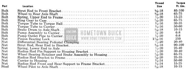
1956 Buick Rear Axle Tightening Specifications
General Specifications
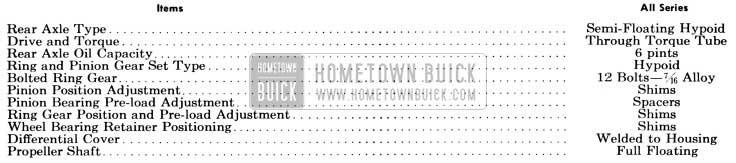
1956 Buick Rear Axle Specifications
1956 Buick Rear Axle Gear Ratios
The following gear ratios are standard; optional gear ratios are not available.
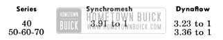
1956 Buick Rear Axle Gear Ratios
The gear ratio is indicated by numbers stamped on bottom of axle housing as follows:
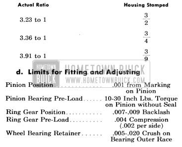
1956 Buick Rear Axle Limits for Fitting and Adjusting
Limits for Fitting and Adjusting (see above)
6-2 DESCRIPTION OF 1956 BUICK REAR AXLE
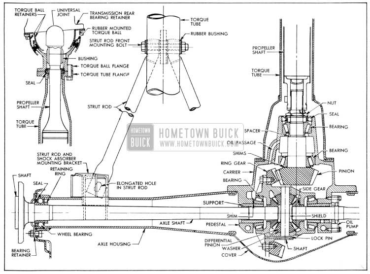
The 1956 Buick rear axle assembly is of the semi-floating type in which the car weight is carried on the axle shafts through ball bearings enclosed in the outer axle housing. It has a full torque tube drive and coil springing. Its final drive is a hypoid type ring gear and pinion with the centerline of the pinion below the centerline of the ring gear. See figure 6-1.
1956 Buick Rear Axle Assembly
The drive pinion is mounted in two tapered roller bearings which are pre-loaded by two selected spacers at assembly. The pinion is positioned by shims located between a shoulder on the drive pinion and the rear bearing. The front bearing is held in place by a staked lock nut. The differential carrier casting has an oil feed passage to the pinion bearings and an oil return hole so that the oil will circulate and cool.
The differential is supported in the carrier by two tapered roller side bearings. These are pre-loaded by inserting shims between the bearings and the pedestals. The differential assembly is positioned for proper gear and pinion back-lash by varying these shims. The bearings are centered on the cross axis by lock taper cones secured in the pedestal bores by clamp bolts. The ring gear is bolted to the case. The case houses two side gears in mesh with two pinions mounted on a pinion axle which is anchored in the case by a spring pin. The pinions are backed by bronze spherical thrust washers.
The axle shaft inner splines engage the differential side gears with a floating fit. The outer ends are supported in the axle housing by thrust type ball bearings which also contain oil seals. The bearings are secured against a shoulder on the shaft by a press fit retainer ring. A retainer plate holds the bearings against shoulders in the housing. Wheel side thrust is taken at the wheel bearings, so an axle shaft may be removed simply by removing the bolts holding the retainer to the brake backing plate and axle housing flange.
The torque tube has an enlarged section at the rear which is bolted to the carrier behind the pinion bearings. This design prevents loads du e to driving and braking forces from causing a deflection resulting in a bind between the pinion bearings.
The propeller shaft is full floating; it is splined at each end and is free to move endwise. The coupling at the rear end is packed with grease at assembly. The splines are designed to permit a slight angular deflection.
The torque ball has two bonded rubber compression rings which act as a double rubber cushion between the ball and the inner and outer retainers. Normal rear axle movements are absorbed by flexing of the rubber without metal to metal contact, thereby cutting down on vibration and noise and providing a leak proof seal.
The strut rods are bolted to the torque tube bracket through rubber compression bushings. This eliminates metal to metal contact.
On 70 series cars only, a vane type oil pump is used to provide a jet of oil at the point where the ring and pinion mesh. This pump is mounted on the right carrier pedestal and is driven by a set of splines on the axle shaft. All axle and propeller shaft splines are of the fine pitch type. This tooth design reduces sliding friction and permits limited angular deflection without bind.
A seal mounted in the rear flange of the torque ball bears against a sleeve pressed on the front end of the propeller shaft to prevent transmission oil from passing into the torque tube. A seal in the front of the carrier bears against the pinion bearing nut to prevent differential gear oil from passing into the torque tube. Each wheel bearing has a built-in oil seal which allows gear oil to lubricate the bearing but prevents oil passage into the brake. See Figure 6-1.
6-3 1956 BUICK REAR AXLE TROUBLE DIAGNOSIS
Elimination of External Noises
When a 1956 Buick rear axle is suspected of being noisy it is advisable to make a thorough test to determine whether the noise originates in the tires, road surface, front wheel bearings, engine, transmission, or 1956 Buick rear axle assembly. Noise which originates in other places cannot be corrected by adjustment or replacement of parts in the rear axle assembly.
- Road Noise. Some road surfaces, such as brick or rough surfaced concrete, cause noise which may be mistaken for tire or rear axle noise. Driving on a different type of road, such as smooth asphalt or dirt, will quickly show whether the road surface is the cause of noise. Road noise usually is the same on drive or coast.
- Tire Noise. Tire noise may easily be mistaken for rear axle noise even though the noisy tires may be located on the front wheels. Tires worn unevenly or which have the surfaces of the non-skid divisions worn in saw-tooth fashion are usually noisy, and may produce vibrations which seem to originate elsewhere in the vehicle. This is particularly true with low tire pressure. Some designs of non-skid treads may be more noisy than others, even when tires are new.
- Test for T ire Noise. Tire noise changes with different road surfaces but rear axle noise does not. Temporarily inflating all tires to approximately 40 pounds pressure, for test purposes only, will materially alter noise caused by tires, but will not affect noise caused by the 1956 Buick rear axle. Rear axle noise usually ceases when coasting at speeds under 30 miles per hour; however, tire noise continues but with lower tone as car speed is reduced. Rea r axle noise usually changes when comparing “pull” and “coast,” but tire noise remains about the same.
- Front Wheel Bearing Noise. Loose or rough front wheel bearings will cause noise which may be confused with rear axle noises; however, front wheel bearing noise does not change when comparing “pull” and “coast.” Light application of brake while holding car speed steady will often cause wheel bearing noise to diminish as this takes some weight off the bearing. Front wheel bearings may be easily checked for noise by jacking up the wheels and spinning them, also by shaking wheels to determine if bearings are loose.
- Engine and Transmission Noises. Sometimes a noise which seems to originate in the 1956 Buick rear axle is actually caused by the engine or transmission. To determine which unit is actually causing the noise, observe approximate car speeds and conditions under which the noise is most pronounced, then stop car in a quiet place to avoid interfering noises. With transmission in neutral, run engine slowly up and down through engine speeds corresponding to car speed at which the noise was most pronounced. If a similar noise is produced with car standing it is caused by the engine or transmission, and not the rear axle.
1956 Buick Rear Axle Noises
If a careful test of the car shows that the noise is not caused by external items as described in subparagraph a, it is then reasonable to assume that the noise is caused by the 1956 Buick rear axle assembly. The 1956 Buick rear axle should be tested on a smooth level road to avoid road noise. It is not advisable to test rear axle for noise by running with rear wheels jacked up.
Noises in the 1956 Buick rear axle assembly may be caused by faulty rear wheel bearings, faulty differential or pinion shaft bearings, differential side gears and pinions worn, or by a mismatched, improperly adjusted or scored ring and pinion gear set.
- Rear Wheel Bearing Noise. A rough rear wheel bearing produces a vibration or growl which continues with car coasting with transmission in neutral. A brinnelled rear wheel bearing causes a knock or click approximately every two revolutions of rear wheel since the bearing rollers do not travel at the same speed as the rear axle and wheel. With rear wheels jacked up, spin rear wheels by hand while listening at hubs for evidence of rough or brinnelled wheel bearing.
- Differential Side Gear and Pinion Noise. Differential side gears and pinions seldom cause noise since their movement is relatively slight on straight ahead driving. Noise produced by these gears will be most pronounced on turns.
- Pinion Bearing Noise. Rough or brinnelled pinion bearings produce a continuous low pitch whirring or scraping noise starting at relatively low speed.
- Ring and Pinion Gear Noise. Noise produced by the ring and pinion gear set generally shows up as drive noise, coast noise, or float noise.
- Drive noise is most evident on constant acceleration through the speed range.
- Coast noise is most evident when car is allowed to coast through the speed range with throttle closed.
- Float noise is most evident while just barely holding the car speed constant on a level road at any speed.
- Drive, coast, and float noises will be very rough and irregular if the differential or pinion shaft bearings are rough, worn, or loose, and will vary in tone with speed.
Check for 1956 Buick Propeller Shaft Vibration
Objectionable vibrations at high speed (65 m.p.h. or higher) may be caused by a propeller shaft that is out of balance. Out of balance may be due to a bent shaft.
To determine whether the propeller shaft is causing vibration, drive car through the speed range and note car speed at which vibration is most pronounced. Shift transmission into second gear (synchromesh) or low range (Dynaflow) and drive car at same engine speed as when vibration was most pronounced in direct drive, and note the effect on vibration.
To determine the required engine speed, divide car speed by the transmission gear ratio, using 1.6 for synchromesh or 1.8 or Dynaflow. Example: If vibration is most pronounced at 65 m.p.h. in direct drive, the same engine speed would be produced in
second gear (synchromesh) at 65 / 1.6 = 40 m.p.h.
or m low range (Dynaflow) 65 / 1.8 = 36 m.p.h.
If the vibration is still present at the same engine speed whether in direct drive or in the lower gear, then the propeller shaft is not out of balance. If the vibration decreases or is eliminated in the lower gear then the propeller shaft is out of balance and should be removed for correction.
Oil Leaks
It is difficult to determine the source of some oil leaks. When there is evidence of an oil leak at these locations, the probable cause is as follows:
- Oil coming from the drain hole shield under the axle housing at the brake backing plate is caused by either a leaking wheel bearing seal or a leaking wheel bearing inner gasket. A leaking inner gasket is generally the result of end-play of the wheel bearing in the axle housing. The wheel bearing must be held tight against the inner gasket to keep oil from leaking out between the bearing outer race and axle housing. See paragraphs 6-6, (c) for correct adjustment.
- Oil coming from between the rear flange of the torque tube and the carrier is caused by either a leaking pinion seal or a leaking propeller shaft seal. The torque tube is normally dry so no gasket is used between the rear flange and the carrier. In a Dynaflow equipped car, leakage of light oil at this point is caused by a defective propeller shaft seal; leakage of heavy oil is caused by a defective pinion seal.
Leave A Comment
You must be logged in to post a comment.