SECTION 3-C – 1956 BUICK FUEL SYSTEM ADJUSTMENT AND REPLACEMENT – EXCEPT IN PUMP AND CARBURETOR ASSEMBLIES
3-7 1956 BUICK AIR CLEANER, GAS FILTER, AND MANIFOLD VALVE SERVICE
1956 Buick Air Cleaner Service
An air cleaner with a dirty element, or with oil that is dirty, too heavy, or too high in the reservoir will restrict the air flow to the carburetor and cause a rich mixture at all speeds. The device will not properly remove dirt from the air and the dirt entering the engine will cause abnormal formation of carbon, sticking valves, and wear of piston rings and cylinder bores.
Regular cleaning of the element and reservoir and re-filling with clean oil at 5000-mile intervals, or more frequently in dusty territory, is necessary to prevent excessive engine wear and abnormal fuel consumption. The procedure for cleaning and refilling the air cleaner is given under Lubricare Instructions, paragraph 1-2.
Cleaning 1956 Buick Gasoline Filter
The 1956 Buick gasoline filter located at carburetor inlet collects dirt and water. The drain plug at the bottom of the inlet side of filter should be removed at 5000 mile intervals to drain out the accumulation of dirt and water.
When a thorough cleaning is required, remove the filter, remove the drain plug and agitate the filter in Bendix Metalclene or its equivalent. Direct air stream through the outlet port of filter to force dirt from the inlet side of filtering disk. Rinse filter in kerosene, distillate, or white gasoline and again direct air stream through the outlet port. Install drain plug and reinstall filter.
Cleaning 1956 Buick Carburetor Gasoline Strainers
A fine mesh strainer is located in some carburetor inlets. This strainer should seldom require cleaning because of the gasoline filter which precedes it in the gasoline supply line. This strainer should be inspected however, if fuel supply at carburetor inlet is adequate but carburetor operation indicates lack of fuel.
Freeing Up Sticking 1956 Buick Exhaust Manifold Valve
Lubrication of the 1956 Buick exhaust manifold valve shaft every 1000 miles is specified in Lubricare Instructions (par. 1-1).
Carbon or lead salt deposits around the valve shaft may cause the valve to stick or become sluggish in operation. A valve sticking in the open position will cause slow engine warm up, excessive spitting and sluggish engine operation when cold. A valve sticking in the closed position will cause overheating, loss of power, and hard starting when the engine is hot, and may also cause warped or cracked manifolds. Sticking in either position will adversely affect fuel economy.
If the valve shaft is sticking or frozen in the manifold, free it up by tapping on the ends with a light hammer, and by rotating the counterweight. Penetrating oil or kerosene may be used to aid in freeing the shaft. When the valve shaft is free, apply a mixture of kerosene and powdered graphite liberally to the shaft bearing; the mixture to be composed of 2 1/2 ounces of powdered graphite to 1 pint of kerosene.
Checking 1956 Buick Manifold Valve Thermostat Setting
The setting of the 1956 Buick exhaust manifold valve thermostat may be checked when the engine is at room temperature of approximately 70° F. Unhook the outer end of thermostat from anchor stud on the manifold and hold the valve in the closed position. To bring the end of thermostat to the anchor stud will then require approximately 3/8 turn wind-up of the thermostat as shown in figure 3-5.
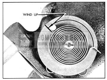
1956 Buick Valve Thermostat Wind-Up
The thermostat is not adjustable and should never be distorted or altered in any way as this will affect its calibration. If the thermostat does not have the proper setting, or is damaged, it should be replaced.
3-8 CARBURETOR AND AUTOMATIC CHOKE ADJUSTMENTS
Carburetor adjustment should not be attempted until it is known that all items affecting engine Ignition and Compression are in good order, as outlined in paragraph 2-9. Any attempt to adjust or alter the carburetor to compensate for faulty conditions elsewhere in items affecting engine performance will result in reduced fuel economy and overall performance.
The two idle needle valves and the throttle stop screw are the only external means provided for adjusting the carburetor for engine performance. The idle needle valves control the idle or low speed system of the carburetor; all adjustments or calibrations affecting the high speed, power, and float systems are accomplished during assembly of the carburetor.
Initial Setting of Idle Needle Valves and Throttle Stop Screw
- With engine stopped, turn both idle needle valves clockwise until they are lightly seated. Forcing valve s hard against seats will score valves and seats and ruin them for proper adjustment.
- On both Carter carburetors, turn each needle OUT (counterclockwise) 1 turn. On Stromberg carburetors, turn each needle OUT 1 3/4 turns. On Rochester carburetors, turn each needle OUT 1 1/4 turns. These settings provide an average starting adjustment.
- Back off throttle stop screw and hold fast idle cam in HOT (choke open) position so that throttle valves are fully closed.
- On all carburetors, turn throttle stop screw IN (clockwise) until it just contacts, then turn screw IN one complete turn. This setting should give an approximate idling speed so that engine can be warmed up for final adjustment as d escribed below.
Final Adjustment of Idle Needle Valves and Throttle Stop Screw
- With throttle stop screw and idle needle valves at the initial settings described above (subpar. a), start the engine and run it until it is at normal operating temperature.
- With engine at normal operating temperature and idling at 450 RPM, adjust one needle valve at a time (fig. 3-6) to provide smooth idle, as follows:
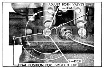
1956 Buick Adjustment of Idle Needle Valves
- Slowly turn needle valve “IN” (clockwise) until engine just begins to lag or run irregularly because of lean mixture.
- Slowly turn needle valve “OUT” until engine just begins to “roll” or “gallop” because of rich mixture.
- Slowly turn needle “IN” just enough to provide the smoothest engine operation.
- Repeat this same procedure on the other needle valve.
Final adjustment of the carburetor idle need le valves also may be made with the aid of a combustion tester, tachometer, or vacuum gauge. When such instruments are used, be sure they are in good condition and are used in accordance with the instructions of the manufacturer.
Regardless of the methods or instruments used for making adjustments in the shop, the correctness of adjustment should be finally checked by a road test for smoothness at idling speed, power on acceleration, and freedom from sluggishness or fiat spots throughout entire speed range.
Checking Float Bowl Level
The sight hole in the float bowl may be used to check for proper fuel level in the bowl on the Rochester carburetor only.
With engine idling at normal operating temperature, remove plug from sight hole. The fuel will be just high enough to wet the threads at lower side of sight holes if the float is correctly adjusted. Securely install plug in sight hole after checking fuel level.
Automatic Choke Adjustments
The choke thermostat is calibrated to give satisfactory performance with regular blends of fuel when it is placed at the standard factory setting, which is at INDEX for all Series carburetors. See figure 3-7.
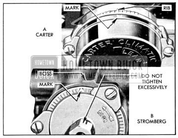
1956 Buick Choke Thermostat Settings
When it is necessary to adjust the thermostat loosen the housing or cover attaching screws and turn as required. On Stromberg choke it is also necessary to loosen the heat pipe connection to turn the cover. When tightening heat pipe connection after adjustment do not use excessive pressure, which may change position of thermostat cover.
Thermostat settings other than standard should be used only when the car is habitually operated on special blends of fuel which do not give satisfactory warm-up performance with the standard setting. A “Lean” setting may be required with highly volatile fuel which produces excessive loading or rolling of engine on warm-up with the standard thermostat setting. A “Rich” setting should be used only when excessive spitting occurs on engine warm-up with the standard thermostat setting. When making either a “Lean” or “Rich” setting, change one point at a time and test results with engine cold, until the desired performance is obtained.
If the engine operates on fast idle too long after starting or else moves to slow idle too soon, or the choke unloader does not operate properly, check the fast idle and choke unloader adjustments as described in paragraph 3-17 (Carter), 3-24 (Stromberg), or 3-29 (Rochester).
3-9 1956 BUICK THROTTLE LINKAGE AND DASH POT ADJUSTMENTS
The procedure for adjusting 1956 Buick throttle linkage is identical on Synchromesh and Dynaflow cars. On Dynaflow cars, however, the throttle linkage actuates other linkage connected to the stator control valve. Also, Dynaflow cars have a dash pot to prevent engine stalling from too rapid release of the accelerator pedal. Therefore, a stator operating lever adjustment and a dash pot adjustment are required on Dynaflow cars in addition to the adjustments necessary on Synchromesh cars.
1956 Buick Throttle Linkage Adjustment
- Make sure that accelerator pedal IS in good condition and that floor mat is properly installed. Then tighten pedal mounting screws.
- Check throttle linkage for proper lubrication. Make sure that pedal rod does not bind going through floor, and make sure that return spring is strong enough to fully close the throttle.
- Adjust throttle stop screw for proper HOT idling speed of 450 RPM (par. 3-8).
- Hold choke valve closed and move throttle to wide open position to check adjustment of choke unloader. If choke unloader does not operate properly, adjust as described in paragraph 3-17 (Carter) or 3-24 (Stromberg), or 3-29 (Rochester).
- On Dynaflow cars, back off the stator pick-up lever adjusting screw until screw end is flush with lever surface. This is because an incorrectly adjusted screw might keep accelerator from contacting floor mat as required in step 8 below.
- Disconnect throttle return spring. Disconnect throttle operating rod from lever on equalizer shaft. See figure 3-8.
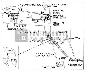
1956 Buick Throttle and Stator Control Linkage
1956 Buick Stator Lever Adjustment (Dynaflow Only)
Adjust 1956 Buick stator lever only after throttle linkage adjustment has been made as described above (subpar. a).
- Have accelerator pedal pressed firmly against floor mat, then turn stator pick-up lever adjusting screw against stator operating lever, raising lever until all vertical play is removed from stator operating control rod. Turn screw back 1/2 turn to provide a slight clearance between stator control valve operating lever and its stop on high accumulator.
- Adjust dash pot as follows (subpar. c).
1956 Buick Dash Pot Adjustment (Dynaflow Only)
Adjust the 1956 Buick dash pot only after the throttle linkage and stator lever adjustments have been made as described above (subpar. a and b) and the engine is at normal operating temperature.
- Open throttle to clear fast idle cam, rotate cam to extreme fast idle position, and allow throttle to close against fast idle cam. See figure 3-9.
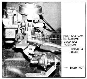
1956 Buick Dash Pot Adjustment
3-10 REPLACEMENT OF 1956 BUICK GASOLINE TANK OR FILLER
When removing 1956 Buick gasoline tank, disconnect feed pipe from gasoline gauge pipe, support the tank while disconnecting support straps at rear ends, then lower tank far enough to disconnect the wire from gasoline gauge.
When installing 1956 Buick gasoline tank by reversing procedure for removal, make sure that all road dirt is cleaned from gasoline gauge and wire terminal; also make sure that wire is securely attached to gauge and that insulation is folded over the terminal and snapped over the wire. An accumulation of road dirt around the gauge terminal may permit an electrical leak that will affect the accuracy of the gauge. Insulating strips must be located between the tank and the upper supports on body.
The 1956 Buick gasoline tank and the filler are furnished separately so that they may be replaced if damaged. After unsoldering the old parts, the new filler should be installed in gasoline tank in accordance with the dimensions given in figure 3-10. Joints must be thoroughly soldered and should be tested for leaks with gasoline before installing gasoline tank.
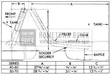
1956 Buick Location Dimensions for Installing Gasoline Tank Filler
Leave A Comment
You must be logged in to post a comment.