SECTION 9-C 1956 BUICK BRAKE SERVICE, ADJUSTMENT, REPAIR PROCEDURES
NOTE: See Paragraph 9-16 for Power Brake Cylinder Service.
9-7 FILLING, BLEEDING, FLUSHING 1956 BUICK BRAKE HYDRAULIC SYSTEM
Filling 1956 Buick Brake Master Cylinder
The master cylinder must be kept properly filled to insure adequate reserve and prevent air from entering the hydraulic system. It must not be overfilled, however, as expansion due to heat absorbed at brakes and from engine would cause fluid to overflow through the vent in filler cap nut. The overflow fluid would accumulate road dust and grit which increases the possibility of foreign material getting into the hydraulic system. Dirt accumulated over the vent holes would affect operation of the master cylinder.
On all cars (with regular or power brakes), the brake fluid reservoir is on the master cylinder which is located under the hood on the left side.
Thoroughly clean filler cap nut before removal to avoid getting dirt into reservoir. Add fluid as required to bring level to 1/2″ to 1″ below top of filler opening. Use G.M. or Delco Super No. 11 Hydraulic Brake Fluid.
CAUTION: Do not use shock absorber fluid or any other fluid which contains mineral oil. Do not use a container which has been used for mineral oil. Even a trace of mineral oil will cause swelling and distortion of rubber parts in the 1956 Buick hydraulic brake system.
Check for clear vent holes in filler cap nut and make sure gasket is in good condition before installing cap nut.
Bleeding 1956 Buick Brake Hydraulic System
A bleeding operation is necessary to remove air whenever it is introduced into the hydraulic brake system. Since air is compressible and hydraulic fluid is not, the pressure of air in the system is indicated by a springy, spongy feeling on the 1956 Buick brake pedal accompanied by poor braking action.
Air will be introduced into the hydraulic system if the 1956 Buick brake pedal is operated when the fluid is too low in master cylinder reservoir. Air will also enter the system whenever any part of hydraulic system is disconnected.
It will be necessary to bleed the hydraulic system at all four wheel cylinders if air has been introduced through low fluid level or by disconnecting brake pipe at master cylinder. If 1956 Buick brake pipe is disconnected at any wheel cylinder, then that wheel cylinder only need be bled. If pipes are disconnected at any fitting located between master cylinder and wheel cylinders, then all wheel cylinders served by the disconnected pipe must be bled. See figure 9-4.
Sequence for Bleeding Wheel Cylinders
It is advisable to bleed one wheel cylinder at a time to avoid getting fluid level in reservoir dangerously low. The correct sequence of bleeding is left front, right front, left rear, right rear. This sequence expels air from the lines and wheel cylinders nearest to the master cylinder first, and eliminates the possibility that air in a line close to the master cylinder may enter a line farther away after it has been bled.
CAUTION: Do not perform bleeding operation while any brake drum is removed.
Bleeding Wheel Cylinder Without Pressure Tank
- Fill master cylinder (subpar. a, above).
- Remove screw and attach Brake Bleeder Tube J 628-A to wheel cylinder bleeder valve. Place lower end of bleeder tube in a clean glass jar. Unscrew bleeder valve 3/4 of a turn, using Bleeder Wrench J 627. See figure 9-6.
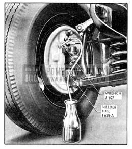
1956 Buick Bleeding Wheel Cylinder
- Depress brake pedal a full stroke, then allow pedal to return slowly to released position. Allowing pedal to return quickly may draw air into system. Continue operating pedal in this manner until fluid flows from bleeder tube into glass jar in a solid stream that is free of air bubbles, then close the bleeder valve securely. Remove bleeder tube and install screw in valve.
- Frequently check master cylinder to make sure that it contains fluid. Approximately 1/2 pint of fluid is required to bleed each wheel cylinder. Allowing reservoir to be emptied will cause air to be drawn into hydraulic system.
- When bleeding operation is completed at all wheel cylinders where needed, make sure that fluid level is 1/2″ to 1″ below top of master cylinder filler opening then install filler cap nut and gasket.
- Discard the brake fluid deposited in glass jar during bleeding operation. It is poor economy to attempt to clean fluid that has once been used.
Bleeding Wheel Cylinder with Pressure Tank
IMPORTANT: When using a pressure tank, air bubbles may form in the tank and enter the 1956 Buick brake hydraulic system. To avoid this, observe the following points when handling a pressure tank: (1) Do not shake or agitate the pressure tank after air pressure has been added or is being added. (2) Allow pressure tank to stand in one position as much as possible, and bring air hose over to tank when adding head of air. (3) Make certain the valves on the pressure tank lines are not defective allowing air to be sucked in when fluid passes through the lines. (4) Pressure tank should be kept at least % full of fluid to avoid air bubbles forming. (5) If pressure tank is full of air bubbles, release air pressure and those bubbles will increase in size and be forced to top of fluid, and escape.
- Thoroughly clean master cylinder filler cap nut and surrounding area, then remove cap nut.
- Make sure that pressure tank is at least 1/3 full of specified brake fluid, that hose and master cylinder reservoir are filled with fluid, then attach hose to master cylinder filler opening.
- Remove screw and attach Brake Bleeder Tube J-628-A to wheel cylinder bleeder valve. Place lower end of bleeder tube in a clean glass jar. Unscrew bleeder valve 3/4 of a turn, using Bleeder Wrench J 627. See figure 9-6.
- Open pressure tank hose valve to apply fluid to master cylinder under pressure that does not exceed 35 pounds. Too much pressure may blow out the expansion plug in master cylinder. It is not necessary to pump the 1956 Buick brake pedal when using pressure tank.
- When fluid flows from bleeder tube into glass jar in a solid stream that is free of air bubbles, that particular cylinder and line are bled; tighten bleeder valve securely, remove bleeder tube and install screw in bleeder valve.
- When bleeding operation is completed at all wheel cylinders where needed, make sure that fluid level is 1/2″ to 1″ below top of master cylinder filler opening then install filler cap nut and gasket.
Flushing 1956 Buick Brake Hydraulic System
It is recommended that the entire hydraulic system be thoroughly flushed and cleaned every 15,000 miles, or whenever new parts are installed in the hydraulic system, or new shoes or linings are installed. Flushing is also recommended if there is any doubt as to the grade of fluid in the system or if fluid has been used which contains the slightest trace of mineral oil.
Flushing is performed at each wheel cylinder in turn, and in the same manner as the bleeding operation except that bleeder valve is opened 1 1/2 turns and the cleaning fluid is forced through the pipes and wheel cylinder until it emerges clear in color. Approximately one quart of cleaning fluid is required to flush the hydraulic system thoroughly.
When flushing is completed at all wheel cylinders, substitute specified brake fluid at master cylinder and repeat the operation at each wheel cylinder in turn until clear brake fluid emerges in a solid stream free of air bubbles. Make sure that all cleaning fluid is forced out of hydraulic system by the fresh brake fluid. Also, make certain that master cylinder reservoir is filled to proper level when job is completed.
9-8 MINOR 1956 BUICK BRAKE ADJUSTMENT
The minor 1956 Buick brake adjustment is intended for use where braking action is equal and generally satisfactory except that brake pedal goes too close to toeboard due to wear of brake linings. If braking action is unequal or otherwise unsatisfactory, the major brake adjustment should be used (par. 9-10).
Do not adjust when 1956 Buick brakes are warm. Brake drums should be approximately room temperature.
Preliminary Checks
- Jack up all four wheels in a safe manner.
- Check fluid level in master cylinder reservoir and add fluid if necessary (par. 9-7).
- Fully release 1956 Buick parking brake lever.
- Pull on both ends of rear brake cable a number of times to make sure that cables operate rear brake shoes freely and do not bind in conduits. Check for free movement of cable in brake ca6le sheave and check brake cable spring for tension. If cable action is not free, the cable and sheave should be lubricated (par. 9-9). Replace a weak or broken cable spring.
- Check all anchor pin nuts with 16″ Wrench J 854 to make certain nuts are tight. See figure 9-9. If an anchor pin nut is found loose, reset anchor pin as instructed in paragraph 9-10, step 19 otherwise do not disturb anchor pins.
- Check 1956 Buick brake pedal adjustment as follows (subpar. b).
1956 Buick Brake Pedal Adjustment
NOTE: See paragraph 9-16 for power brake pedal adjustment.
No brake pedal adjustment is necessary for the direct acting master cylinder used on cars with regular brakes. However, the pedal must return freely to the fully released position with the piston guide contacting the bumper washer. If pedal does not return fully, the compensating holes in the piston will not clear the primary cup and pressure will build up in the 1956 Buick brake system. See Figure 9-7.
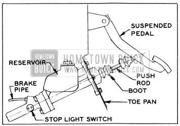
1956 Buick Brake Pedal Adjustment
Adjustment at Wheels
- Remove adjusting hole covers from brake backing plates. Using suitable tool to turn brake adjusting screw, expand 1956 Buick brake shoes at each wheel until the wheel can just be turned by hand. Moving outer end of tool upward toward center of wheel expands the shoes. See figure 9-8. The drag should be equal at all wheels.
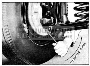
1956 Buick Expanding Brake Shoes
- With shoes expanded in both rear drums and parking brake lever fully released, check parking brake cables for proper tension. While holding brake lever cable end to prevent twisting, tighten cable adjusting nut at cable sheave to remove any slack from rear brake cable. Back off nut if cable is under tension. NOTE: Make sure that cable sheave is horizontal, otherwise it may slap against torque tube on bumpy roads.
- Back off brake adjusting screw at each wheel 15 notches. If shoes still drag lightly on drum, back off adjusting screw one or two additional notches, NOTE: Brakes should be free of drag when screw has been backed off approximately 6 notches. Heavy drag at this point indicates improper anchor pin setting or tight parking brake cables.
- Install adjusting hole covers in all brake backing plates when adjustment is completed.
- Remove jacks and road test car for service and parking brake performance (par. 9-5).
9-9 PARKING 1956 BUICK BRAKE ADJUSTMENT CABLE LUBRICATION
Adjustment
Adjustment of the 1956 Buick parking brake is included in the minor brake adjustment described in paragraph 9-8. It is advisable to use the complete minor brake adjustment if the position of brake pedal, when applied, indicates that some brake lining wear has taken place since brakes were last adjusted. In this case, adjustment of parking brakes only will result in the front brake shoes having more clearance than the rear shoes.
If 1956 Buick brake linings have not worn appreciably, it is permissible to adjust parking brakes separately to take up slack in brake cables. Jack up rear wheels only and adjust parking brakes by performing minor adjustment given in paragraph 9-8 (subpar. c). Do not attempt to adjust parking brakes by simply tightening adjusting nut at brake cable sheave as this practice may result in taking up necessary clearance of brake shoes and cause them to drag.
Cable Lubrication
Lubrication of parking cables is not included in Lubricare Instructions (par. 1-1) since these cables are usually lubricated during a major brake adjustment. Vehicles habitually operated under conditions where mud and water are frequently encountered may require more frequent lubrication to insure free action and avoid excessive wear of cables.
- Disconnect 1956 Buick brake lever cable at cable sheave (equalizer). See figure 9-3.
- Disconnect rear brake cable conduits from rear brake backing plates and from clips on strut rods.
- Slide each conduit away from backing plate and coat the cable sparingly with Bendix or Delco Brake Lubricant, or Lubriplate. Also lubricate cable where it passes through the sheave and make sure cable slides freely in sheave.
- Slide conduit to within 2″ of normal position, then clean surplus lubricant from cable at backing plate to avoid forcing it into brake assembly where it will get on brake linings.
- Connect conduits to clips on strut rods and to backing plates.
- Although the brake lever cable rarely needs lubrication it may be lubricated at this time by disconnecting cable at brake lever and removing exposed portion from grommets under torque tube. Heavily coat exposed section under torque tube with graphite lubricant, then pull cable out of conduit at upper end. This will cause lower section of cable to deposit lubricant in rear end of conduit. Coat upper end of cable with graphite lubricant, then pull upper end of cable back into conduit and connect to brake lever.
- Connect brake lever cable at cable sheave and adjust parking brakes (subpar. a).
9-10 MAJOR 1956 BUICK BRAKE ADJUSTMENT
The major brake adjustment is intended for use when new shoes or linings are installed. It is also to be used when brake action is unequal, severe, or otherwise unsatisfactory.
Throughout the adjustment procedure additional operations are specified where inspection indicates their need. Each additional operation is identified by an asterisk (*) preceding the reference to paragraph number covering the operation. The major brake adjustment combined with required additional operations constitute a general overhaul of the entire 1956 Buick brake mechanism.
- Jack up car in a safe manner and remove all wheels.
- Check fluid level in master cylinder reservoir and add fluid if necessary (par. 9-7).
- Check 1956 Buick brake pedal for free action, proper return to stop, and proper clearance at toeboard (par. 9-8, a).
- Pump brake pedal a number of times with quick release. If pedal develops a very solid feel and reduced travel, and brakes drag heavily when drums are turned, it indicates that the compensating port in master cylinder is blocked by a distorted piston primary cup. If brake pedal goes slowly down when steady pressure is applied, and no leaks are found in inspection described later, it indicates a distorted primary cup or scored master cylinder barrel. Either condition requires overhaul of master cylinder (*par. 9-14).
- Inspect all brake pipe and hose connections for evidence of fluid leakage. See figure 9-4. Tighten any leaking connection, apply heavy pressure to brake pedal to build pressure in hydraulic system, and recheck connections.
- Remove rear brake drums, and front hub and drum assemblies. NOTE: Brake pedal must not be operated while drums are removed.
- Clean all dirt out of brake drums, using care to avoid getting dirt into front wheel bearings. Inspect drums and replace or recondition if required (*par. 9-12).
- Inspect front wheel bearings and oil seal packings. Replace faulty bearings or packings (*par. 7-10).
- Blow all dirt from brake assemblies, then inspect 1956 Buick brake linings for wear, oil soaking, loose rivets, and imbedded foreign particles.
If linings are oil soaked, replacement is required (*par. 9-11).
If linings are worn down to rivets, or the total thickness of lining and shoe rim at thinnest point is less than .180″ (measured with ball micrometer), replacement is required (*par. 9-11).
If total thickness of lining and shoe rim is .200″ at thinnest point, car owner should be warned that lining replacement will be required in 3000-5000 miles.
If linings are otherwise serviceable, tighten or replace loose rivets and thoroughly clean all steel or other imbedded particles from surfaces and rivet counterbores of linings.
When a rivet head is touching the drum and total thickness of lining and rim is more than .200″, it is permissible to remove the rivet to prevent scoring of drum except when rivet is at end of lining. Not more than one rivet may be removed from each row of rivets.
If 1956 Buick brake linings at any wheel show a spotty wear pattern indicating uneven contact with 1956 Buick brake drum it is advisable to true up the linings with a light grinding cut, if suitable grinding equipment is available. If brake action was unequal, severe or hard, indicating that brake shoes were not centralized in drums, the grinder may also be used to correct this condition.
The grinding equipment should locate and swing off the wheel spindle or axle shaft so that shoes will be ground concentric with drums. The instructions of equipment manufacturer must be carefully followed.
- Carefully pull lower edges of wheel cylinder boots away from cylinders and note whether interior is wet with brake fluid. Fluid at this point indicates leakage past the piston cup, requiring overhaul of wheel cylinder (*par. 9-13).
- Inspect rear brake backing plates for oil leaks past wheel bearing oil seals. Correct any oil leaks by installation of new seals (*par. 6-6).
- Check all backing plate attaching bolts to make sure they are tight. Check anchor pin nuts for tightness, using Wrench J 854 (fig. 9-9). If an anchor pin nut is found loose, anchor pin must be reset as described later (step 19).
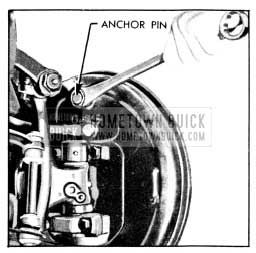
1956 Buick Using Anchor Pin Nut Wrench J 854
- Lubricate parking brake cables (par. 9-9). Cables will be adjusted later.
- If 1956 Buick brake shoes were not removed for additional work, pry shoes away from backing plates and clean all rust and dirt from contact surfaces on shoes and plates, using fine emery cloth. Lubricate contact surfaces with a thin coating of Bendix or Delco Brake Lubricant, or Lubriplate. On rear brakes, sparingly apply the same lubricant to parking brake strut and backing plate boss under the brake cable.
- Lubricate front wheel bearings, install hub and drum assemblies and adjust wheel bearings (par. 7-10).
- Install rear brake drums. Remove adjusting hole covers from all backing plates.
- If brake action was unequal, severe, or hard, it is probable that the shoes were not properly centered in the drums. If grinding equipment is not available for use as specified in Step 11, shoes may be centered in drums by adjusting the anchor pin at each wheel as follows:
- Using suitable tool (fig. 9-8) turn brake adjusting screw to expand brake shoes until drum can just be turned with a long bar, giving a drag equivalent to a two-hand drag with wheel installed.
- Use Wrench J 854 (fig. 9-9) to loosen anchor pin nut just enough so that pin can shift in slotted hole in backing plate. If nut is loosened too much, the anchor pin will tilt due to pull of 1956 Buick brake shoe springs.
- Rap backing plate with hammer adjacent to anchor pin to cause pin to shift into central position between ends of brake shoes. Check brake drag with bar and tighten adjusting screw if drag has decreased, rap backing plate, and recheck brake drag.
- When anchor pin has been shifted into a central position between ends of shoes as described, tighten anchor pin nut securely.
- Tightening anchor pin nut should not change the brake drag previously obtained. If it does, repeat the procedure without loosening anchor pin nut quite as much, and tap on anchor pin nut if necessary to shift anchor pin.
- Install all wheels, turn adjusting screws to provide an equal two-hand drag, then adjust parking brake cables and adjust shoes for proper clearance as described in paragraph 9-8, (subpar. c).
- If any hydraulic connections were disturbed or if master cylinder reservoir was pumped dry, bleed hydraulic system at affected wheel cylinders (*par. 9-7). If new parts were installed in hydraulic system, or brake fluid has been in service 15000 1niles, flushing of hydraulic system is recommended (*par. 9-7).
- If car is equipped with a parking brake release warning signal, check its adjustment as described in paragraph 10-51.
- Remove jacks and road test car for service and parking brake performance (par. 9-5).
9-11 REPLACE OR RELINE 1956 BUICK BRAKE SHOES
The most satisfactory method of replacing 1956 Buick brake lining is to install new shoe and lining assemblies. This insures 1956 Buick brake shoes that are not distorted through use, and linings properly riveted to shoes and ground to correct radius by accurate factory machinery.
Each 1956 Buick brake shoe and lining set listed under Group 5.017 is packed in a carton containing two primary and two secondary shoe and lining assemblies, enough for two wheels. Sets are available in standard size and also in .030″ oversize for use where brake drums have been rebored.
Use brake shoe lining sets listed under Group 5.018 if the old brake shoes are to be relined. Each lining set is packed in a carton containing two primary and two secondary linings, enough for two wheels. Linings are shaped, drilled, and ground to correct thickness and radius, and are packaged with enough rivets for installation on shoes. Lining sets are available in standard and .030″ oversizes.
To assure an adequate supply, several optional types of brake shoe lining have been approved for production and service. Since the optional types of lining have slightly different characteristics it is important to use primary and secondary shoe linings that are matched according to engineering specifications, and to use the same type of linings on right and left sides at front or rear end of car. It is not possible to identify the various types of lining by inspection; however, each carton listed under Groups 5.017 and 5.018 contains correctly matched primary and secondary linings. The parts from several different cartons should not be used at one end of a car; however the linings at front and rear brakes do not have to be of the same type.
1956 Buick brake linings are made of asbestos for its heat resisting qualities and compounds of bonding material for strength. Some bonding materials are used for their lubricating qualities to guard against drum scoring while others are used to control the friction producing property of the lining, called “coefficient of friction.” Good molded linings also have imbedded particles of material used to control friction and wear. When linings are ground, some of the surface particles may be pulled out, giving a pitted appearance. These pits do not affect lining efficiency.
The heat generated by friction will produce different effects in different compounds of bonding material. Some compounds increase friction with increased temperature, which might cause grabbing or locking. Other compounds lose friction with increased temperature, which might cause materially lowered braking power. Brake lining compounds must be carefully selected to produce the braking friction required at the temperatures normally attained in each vehicle application.
The linings of all shoes in all series have a radial groove 3/8″ wide and half the lining thickness in depth. This groove relieves the high pressure area over the web of the shoe to increase the responsiveness of the 1956 Buick brakes.
Since the many factors which govern the selection of brake lining vary widely in different vehicle designs, it is impossible to compound one lining which will work satisfactorily on all cars. Buick engineered brake lining has been selected after exhaustive tests of all types of lining and with complete consideration of all the requirements existent in the various Buick models. The service man does not have the facilities for making similar tests and improving on the selection of lining; therefore the only safe rule to follow is to use Buick engineered brake lining.
Removal end Inspection
NOTE: When paragraph references in parentheses () have an asterisk (*) the operation referred to is additional work not covered by the standard replacement operation.
- Jack up car in a safe manner, remove wheel, then remove 1956 Buick brake drum (rear) or drum and hub assembly (front). NOTE: Stops located on the backing plates will prevent pistons from leaving the wheel cylinders; however, brake pedal must not be operated while a brake drum is removed.
- Unhook shoe return springs from anchor pin, using Brake Spring Remover KMO 526A or large pliers. Remove shoe hold down springs, spread shoes to clear wheel cylinder connecting links, remove parking brake strut (rear only), and remove shoes from backing plate. Disconnect cable from parking brake lever (rear only). See figure 9-10.
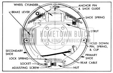
1956 Buick Rear Wheel Brakes Assembly-Right
- Separate the 1956 Buick brake shoes by removing adjusting screw and lock spring. Remove parking brake lever from secondary brake shoe (rear lever (rear only). See figure 9-10.
- Clean all dirt out of brake drum, using care to avoid getting dirt into front wheel bearings. Inspect drums and replace or recondition if required (*par 9-12). If front drum and hub is removed, inspect wheel bearings and oil seal packings and replace faulty parts (*par. 7-10).
- Carefully pull lower edges of wheel cylinder boots away from cylinders and note whether interior is wet with brake fluid. Fluid at this point indicates leakage past piston cup, requiring overhaul of wheel cylinder (*par. 9-13).
- If working at rear wheels, inspect backing plate for oil leak past wheel bearing oil seals. Correct any leak by installation of new seals (*par. 6-6).
- Check all backing plate attaching bolts to make sure they are tight. Clean all rust and dirt from shoe contact surfaces on plate, using fine emery cloth.
Relining 1956 Buick Brake Shoes
If old brake shoes are to be relined, inspect shoes for distortion and for looseness between the rim and web; these are causes for discarding any shoe. If shoes are serviceable, be governed by the following points in installing new linings:
- Remove old linings by drilling out rivets. Punching rivets out will distort shoe rim. Thoroughly clean surface of shoe rim and file off any burrs or high spots.
- Use only genuine Buick brake lining and the rivets included in lining package which are of correct size. The rivets must fit the holes and the solid body of rivet should extend through the shoe rim, but no farther.
- Keep hands clean while handling brake lining. Do not permit oil or grease to come in contact with lining.
- Start the riveting at center of shoe and lining and work toward the ends. Use a roll set for riveting; a star set might split the tubular end and then the rivet would not fill the hole. The primary lining is shorter than secondary lining, therefore the rivet holes at each end of shoe rim are not used.
- After riveting is completed, lining must seat snugly against shoe with no more than .005″ separation midway between rivets. Check with a .004″ (permissible) and a .006″ (no go) feeler gauge.
Installation and Adjustment
- If working on rear brakes, lubricate parking brake cable (par. 9-9).
- On rear brakes only, lubricate fulcrum end of parking brake lever and the bolt with Bendix or Delco Brake Lubricant, or Lubriplate, then attach lever to secondary shoe with bolt, spring washer, nut, and Pal nut. Make sure that lever is free moving. See figure 9-10.
- Connect 1956 Buick brake shoes together with lock spring, then place adjusting screw, socket, and nut in position. The socket and star wheel must be adjacent to primary shoe on front brake, and adjacent to secondary shoe on rear brake.
- Attach brake shoes to backing plate with hold down springs, pins, and cups, at the same time engaging shoes with wheel cylinder connecting links. The primary shoe (short lining) goes forward. On rear brakes, connect cable to parking brake lever and install strut between lever and primary shoe as installation is made. See figure 9-10.
- If old brake shoe return springs are nicked, distorted, or of doubtful strength it is advisable to install new ones. Hook springs in shoes and over end of anchor pin, using KMO 526A or large pliers and being careful not to nick or distort springs.
- Pry shoes away from backing plate and lubricate shoe contact surfaces with a thin coating of Bendix or Delco Brake Lubricant, or Lubriplate. On rear brakes, sparingly apply same lubricant where brake cable contacts backing plate.
- Install 1956 Buick brake drum and wheel. If working on front brake lubricate and adjust front wheel bearings (par. 7-10). Remove adjusting hole cover from backing plate.
- Centralize 1956 Buick brake shoes and set anchor pin, then adjust all brake shoes and brake cable as described in paragraph 9-10, steps 17 through 22.
IMPORTANT: Brakes must not be severely applied immediately after installation of new brake shoes or linings. Severe application may permanently injure new linings and may score brake drums. When linings are new they must be given moderate use for several days until nicely burnished.
9-12 INSPECTING AND RECONDITIONING 1956 BUICK BRAKE DRUMS
Whenever 1956 Buick brake drums are removed they should be thoroughly cleaned and inspected for cracks, scores, deep grooves, and out-of -round. Any of these conditions must be corrected since they can impair the efficiency of brake operation and also can cause premature failure of other parts.
Cracked, Scored, or Grooved Drum
A cracked drum is unsafe for further service and must be replaced. Welding a cracked drum is not recommended.
Smooth up any slight scores by polishing with fine emery cloth. Heavy or extensive scoring will cause excessive brake lining wear and it will probably be necessary to rebore in order to true up the braking surface.
If the 1956 Buick brake linings are little worn and drum is grooved, the drum should be rebored just enough to remove grooves and the ridges in the lining should be lightly removed with a lining grinder.
If 1956 Buick brake linings are more than half worn, but do not need replacement, the drum should be polished with fine emery cloth but should not be rebored. At this stage, eliminating the grooves in drum and smoothing the ridges on lining would necessitate removal of too much metal and lining, while if left alone, the grooves and ridges match and satisfactory service can be obtained.
If 1956 Buick brake linings are to be replaced, a grooved drum should be rebored for use with oversize linings (subpar. c, below). A grooved drum, if used with new lining, will not only wear the lining but will make it difficult, if not impossible, to obtain efficient brake performance.
Out-of-round or Tapered Drum
An out-of-round drum makes accurate brake shoe adjustment impossible and is likely to cause excessive wear of other parts of brake mechanism due to its eccentric action. An out-of-round drum can also cause severe and very irregular tire tread wear.
A drum that is more than .010″ out-of-round on the diameter is unfit for service and should be rebored (subpar. c, below). Out-of-round as well as taper and wear can be accurately measured with an inside micrometer fitted with proper extension rods.
When measuring a drum for out-of-round, taper, and wear, take measurements at the open and closed edges of machined surface and at right angles to each other. Standard drums are machined to an inside diameter of 12.017″ to 12.023″, with runout of braking surface held within .005″ total indicator reading.
Reboring 1956 Buick Brake Drum
If a drum is to be rebored, enough metal should be removed to obtain a true, smooth braking surface. If a drum does not clean-up when rebored to a diameter of 12.063″, it must be replaced. Removal of more metal will affect dissipation of heat and may cause distortion of the drum.
A newly bored drum should always have center point contact with the shoes on initial break-in, thus insuring greater uniformity in brake performance with less danger of brake pulling. To get this desired condition, the shoe radius should always be .020″ less than the drum radius (or .010″ less on the diameter). This fit may be accomplished by either grinding the shoes or boring the drums, whichever is the more practical.
If cleaning-up a drum required boring to a size too large to accomplish this fit (shoe radius .020″ less than drum radius) using standard size brake lining, then .030″ oversize lining must be used.
Fit between the 1956 Buick brake shoes and the drum must always be the same on both sides of the car to get equal braking action.
Brake drums may be refinished either by turning or grinding. Best brake performance is obtained by turning drums with a very fine feed. Ground and polished drums do not wear in as readily as turned drums and are more likely to cause unequal braking when new. To insure maximum lining life, the refinished braking surface must be smooth and free from chatter or tool marks.
Run-out of the refinished surface of brake drum must not exceed .005″ total indicator reading. Run-out of the open edge (opposite the disk) of drum must not exceed .030″.
1956 Buick Brake Drum Balance
During manufacture, 1956 Buick brake drums are balanced within 6 inch ounces by welding weights, as required, to the disk near the rim. These weights must not be removed.
After drums are rebored, or if difficulty is experienced in maintaining proper wheel balance, it is recommended that brake drums be checked for static balance. Drums out of balance more than 6 inch ounces may be corrected by installation of service balance weights as shown in figure 9-11. These balance weights are furnished in three sizes under Group 5.810. Brake drums may be checked for balance on any machine suitable for balancing wheels.
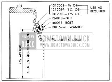
1956 Buick Brake Drum Balance Weights-Service Application
9-13 1956 BUICK BRAKE WHEEL CYLINDER OVERHAUL
- Remove wheel, drum, and 1956 Buick brake shoes. Be careful not to get grease or dirt on brake lining.
- Disconnect brake pipe or hose from wheel cylinder and cover opening with tape to prevent entrance of dirt. Remove wheel cylinder from backing plate.
- Remove links, boots, pistons, cups, cup expanders and spring from cylinder. Remove bleeder valve.
- Discard rubber boots, expander assembly, and piston cups. Thoroughly clean all other parts with hydraulic brake fluid or a good grade of alcohol. CAUTION: Do not use antifreeze alcohol, gasoline, kerosene, or any other cleaning fluid that might contain even a trace of mineral oil.
- Inspect pistons and cylinder bore for scores, scratches, or corrosion. Light scratches may be polished with crocus cloth. Do not use emery cloth or sandpaper. Slight corrosion may be cleaned with fine steel wool and alcohol. If scratches or corroded spots are too deep to be polished satisfactorily the cylinder should be replaced since honing is not recommended.
- Dip internal parts in brake fluid and reassemble wheel cylinder. When installing piston cups use care to avoid damaging the edges,
- NOTE: Front wheel cylinder pistons and cups are 1%” diameter and rear wheel cylinder parts are 1″ diameter.
- Install wheel cylinder on brake backing plate and connect brake pipe or hose.
- Install 1956 Buick brake shoes, drum, and wheel, then flush and bleed hydraulic system (par. 9-7).
- Adjust brakes (par. 9-8) then road test car for brake performance (par. 9-5 and 9-6).
9-14 1956 BUICK BRAKE MASTER CYLINDER OVERHAUL
- Disconnect brake pipe from master cylinder and tape end of pipe to prevent entrance of dirt.
- Disconnect stop light wires from stop light switch.
- Disconnect push rod from brake pedal and remove 1956 Buick brake pedal.
- Remove screws holding steering column jacket rubber seal retainer to toe pan and push it up on the steering column jacket.
- Pull the floor mat away from pedal plate and remove pedal plate and master cylinder together.
- Remove pedal plate from master cylinder. A heat shield must also be removed if car is equipped with a synchromesh transmission.
- Clean outside of master cylinder thoroughly, remove filler cap and drain hydraulic fluid from reservoir.
- Place master cylinder in vise in vertical position with push rod up. Remove boot from push rod and using No. 1 Truarc Ring Pliers, J-4245, remove retaining ring and guide bumper washer. Remove push rod and piston from body.
- Remove return spring, retainer and piston washer. To disassemble push rod from piston, insert the piston into a 6″ I.D. washer and support the washer on the jaws of a vise.
CAUTION: Protect the piston from jaws of vise with a cloth. Do not clamp piston in vise. Hold piston and strike the push rod with a soft headed mallet to drive piston out of piston guide. See Figure 9-12. Then remove grommet and push rod retainer from end of push rod.
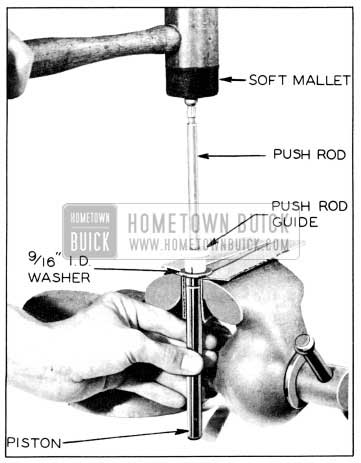
1956 Buick Disassembly of Push Rod and Piston
- Turn cylinder end for end and remove three bolts that hold hydraulic cylinder to body.
- From the hydraulic cylinder remove the primary cup insert, primary cup and primary cup spacer.
- From the body remove primary cup washer, „O“ ring, bearing, secondary cup retainer, secondary cup expander, secondary cup and secondary cup support.
- Discard primary cup, primary cup insert, bearing, „O“ ring, secondary cup expander, secondary cup, piston guide, grommet, retaining ring, boot and filler cap gasket as these parts are supplied in the master cylinder repair kit.
- Inspect the bore of the hydraulic cylinder for rust or dirt. Special attention should be given the 5/8″ counterbore. This surface must be free from scores, pits and rust. Check the machined face for any marks that would endanger the „O“ ring seal. Check threads and be sure outlet fitting hole is open and clean.
Inspect the bore from push rod end for pits, scoring, rust and dirt. Check counterbore on opposite end. This surface must be smooth and free from pit marks, scores, rust and dirt. Check the machined face and threads in three mounting holes at each end of cylinder. Be sure the reservoir is clean and the filler cap hole threads are undamaged. Make sure the hole from the reservoir to the bore is clean and open. Remove stop light switch from nose piece and check threads of switch and casting hole.
The body castings and all parts may be washed in a good grade of clean alcohol. Never use gasoline, kerosene, or any mineral base oil. Inspect all parts after cleaning and replace any that are damaged or worn. Replace filler cap and new gasket loosely in reservoir to keep out dirt during assembly. Replace stop light switch.
The bores of the master cylinder body and nose piece may be cleaned and reconditioned with fine crocus cloth if not too deeply pitted or scratched. The chrome finish of the piston should never be sanded. The piston should be replaced if damaged along with all other internal working parts.
- Make certain the small compensating ports in end of hydraulic piston are clear. If these ports are plugged, clean them thoroughly and flush the hydraulic system to remove all dirt.
- Place piston guide on push rod and move to a position so that the push rod retainer and grommet can be installed on end of push rod. Install piston guide on piston so that land of piston guide engages the groove of the piston. Install piston washer, spring retainer, and return spring on piston.
- Place push rod and piston assembly in body and insert guide bumper washer and retaining ring using No. 1 Truarc Ring Pliers, J-4245. Replace boot on push rod and turn cylinder end for end.
- In the body place secondary cup support, secondary cup, secondary cup expander, secondary cup retainer, bearing, „O“ ring, primary cup washer, and primary cup insert.
- In the hydraulic cylinder place primary cup spacer and primary cup.
- Bolt hydraulic cylinder to body and check filler cap nut vent holes to make sure they are clean, then install cap nut and gasket.
- To install cylinder in car, reverse removal procedure.
- Bleed hydraulic system (par. 9-7).
- Road test car for brake performance.
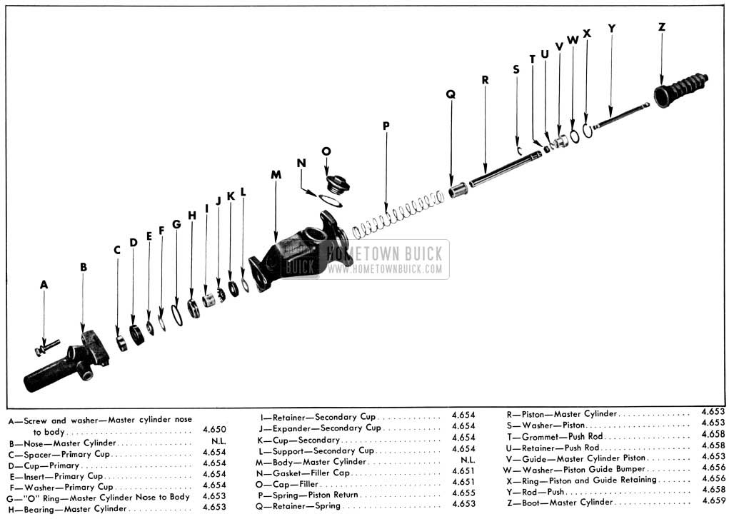
1956 Buick Master Cylinder Exploded View
Leave A Comment
You must be logged in to post a comment.