SECTION 5-C 1955 BUICK DYNAFLOW TRANSMISSION REMOVAL AND INSTALLATION, DISASSEMBLY AND ASSEMBLY
5-13 1955 BUICK DYNAFLOW REMOVAL AND INSTALLATION
Removal of 1955 Buick Dynaflow Transmission
- Hoist front and rear of car and rest it solidly on stands placed under frame. Frame side rail should be at least 20″ above floor.
- Disconnect torque tube from torque ball and move rear axle back to disengage propeller shaft from universal joint.
- Remove cranking motor splash pan, bell housing cover and bell housing hand hole cover.
- Turn flywheel until one converter drain plug can be loosened sufficiently to provide an air vent, then turn flywheel until opposite drain plug is straight down. Remove this plug and allow oil to drain from converter.
- Remove plug from oil pan to drain oil from 1955 Buick Dynaflow transmission.
- Remove bolts to disconnect converter from flywheel.
- Disconnect pipes from oil cooler, disconnect cooler from transmission rear mounting thrust plate and move cooler with attached hoses to a safe place.
- Disconnect oil filler pipe at rubber hose and disconnect exhaust pipe hanger at right accumulator.
- Disconnect speedometer cable, disconnect shift rod from shift lever, and disconnect stator operating control rod from lever on high accumulator.
- Place transmission jack or hoist in position and adjust it to securely support the transmission in accordance with instructions for the equipment being used.
- Remove four bolts that attach the thrust plate to rear bearing retainer, then remove two nuts and plate which attach mounting pad to transmission support. See figure 2-41.
- Raise engine and 1955 Buick Dynaflow transmission just enough to relieve load on transmission support, remove bolts attaching each end of support to frame, then remove support and thrust plate as an assembly. NOTE: Shims may or may not be used to fill space between the transmission support and frame. If shims are present note the number and location of shims so that they can be reinstalled in their original position.
- Place suitable jack under rear end of engine lower crankcase so that engine will be safely supported while transmission is removed. CAUTION: Do not use bar with hooks placed over frame side rails because brake pipes on top of left side rail will be damaged.
On car equipped with Air Conditioner, disconnect high and low pressure lines at compressor (par. 11-8) to avoid damaging these lines when raising or lowering engine. - Lower the 1955 Buick Dynaflow transmission just enough so that bell housing bolts can be reached. With engine and transmission supported by the separate jacks, disconnect the bell housing from engine crankcase.
- Move 1955 Buick Dynaflow transmission rearward to disengage hub of converter pump cover from crankshaft, lower transmission and remove it from under car.
Installation of 1955 Buick Dynaflow Transmission
- Turn flywheel so that one hole for converter drain plug is straight down and turn converter so that corresponding drain plug is straight down.
- Raise transmission into place with same equipment as used for removal. Align converter drain plugs and cover bolts with holes in flywheel before moving transmission forward against cylinder crankcase.
- Adjust lifting equipment so that bell housing meets the engine crankcase squarely and engages the two dowels. Then install all bell housing bolts with lockwashers. Tighten all bolts uniformly to 45-55 ft. lbs. torque.
- Raise transmission just enough to install transmission support and thrust plate, installing shims in their original locations between support and frame. Attach mounting pad to support with plate and nuts, and attach thrust plate to bearing retainer with four bolts and lockwashers.
- Remove transmission hoist and engine support or jack.
- Check converter drain plugs for tightness, then install bell housing and hand hole covers and cranking motor splash pan.
- Attach exhaust pipe hanger to transmission and connect oil filler pipe to oil pan pipe, with both pipes contacting inside the rubber connector.
- Install oil cooler on 1955 Buick Dynaflow transmission rear mounting thrust plate and connect the oil pipes.
- Connect torque tube to torque ball with bolts and lockwashers.
- Connect speedometer cable to driven gear sleeve and connect shift rod to shift lever on transmission. Connect stator operating control rod to lever on high accumulator.
- Wipe all oil from outside of transmission then lower car to floor.
- Fill 1955 Buick Dynaflow transmission to proper level as described in paragraph 1-4.
- Check adjustment of control linkage (par. 5-12). Check adjustment of stator operating controls and throttle linkage (par. 3-9).
On car equipped with Air Conditioner, connect high and low pressure lines to compressor (par. 11-8). - Road test car for approximately 20 miles with frequent stops and starts as might be encountered in heavy traffic. A thorough road warm-up is desired.
- Place car on hoist and carefully examine the 1955 Buick Dynaflow transmission and all connections for oil leaks. Recheck oil level.
5-14 DISASSEMBLY OF 1955 BUICK DYNAFLOW TRANSMISSION TO REMOVE MAJOR PARTS AND UNITS
Preliminary Instructions
- Before starting disassembly of the 1955 Buick Dynaflow transmission it should be thoroughly cleaned externally to avoid getting dirt inside.
- Place transmission on a CLEAN work bench and use CLEAN tools during disassembly and assembly. Provide CLEAN storage space for parts and units removed from transmission.
- The transmission contains parts which are ground and highly polished, therefore, parts should be kept separated to avoid nicking and burring surfaces.
- When disassembling 1955 Buick Dynaflow transmission carefully inspect all gaskets at times of removal. The imprint of parts on both sides of an old gasket will show whether a good seal was obtained. A poor imprint indicates a possible source of oil leakage due to gasket condition, looseness of bolts, or uneven surfaces of parts.
- None of the parts require forcing when disassembling or assembling transmission. Use a rawhide or similar soft mallet to separate tight fitting cases-do not use a hard hammer.
- It is good practice to reassemble parts in the same relative position as they were originally assembled, however, parts must not be prick punched or filed for assembly identification. The wear pattern of the parts will usually indicate their original assembly positions.
Removal of 1955 Buick Dynaflow Converter and Bell Housing
NOTE: This operation not required for removal of valve and servo body, universal joint, or rear bearing retainer.
- Remove both drain plugs from 1955 Buick Dynaflow converter pump cover to drain any oil remaining in converter.
- Remove all nuts, plain washers, and bolts attaching cover to converter pump, then remove cover. Check the cover seal for damage or evidence of oil leakage before removing it from cover.
- Remove reverse band adjustment cover and gasket, using Removing Tool J 2655. Shift into “Parking” and pry up on reverse band operating lever with screwdriver to lock input shaft while removing the bolt, lockwasher, retaining washer and thrust washer from front end of input shaft. See figure 5-25.
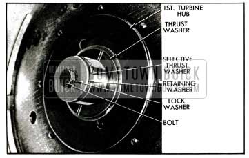
1955 Buick Turbine Retaining Washer and Thrust Washer
- Insert screwdriver into a hole in the first turbine disk to aid in removing the twin turbine assembly from the input shaft. Remove bronze thrust washer from turbine hub.
- Turn the sun gear clockwise to make sure it free wheels, then turn it counterclockwise to make sure it locks in this direction. Remove sun gear assembly with thrust washer from reaction shaft. See figure 5-26.
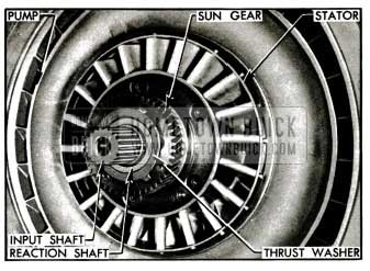
1955 Buick Sun Gear, Stator, and Converter Pump
- Install Tool J 5806 over input shaft with beveled end outward. Pull stator forward on reaction shaft, grasp thrust washer located behind the stator to retain all free wheeling parts in the stator, then slide the assembly forward upon the tool and remove from input shaft. See figure 5-27.
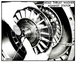
1955 Buick Removing Stator Assembly
- Pull the 1955 Buick Dynaflow converter pump forward from the reaction shaft and immediately check for evidence of oil leakage. Radial streaks of fresh oil on back of pump and fresh oil streaks on face of front oil pump body indicate leakage past the oil pump seal.
- Before removing the bell housing check to see whether all attaching bolts are tight. Loose bolts may be the cause of oil leakage at this point.
- Put bell housing over edge of bench and remove it. Examine the rubber oil seal located around the front oil pump to see whether it has been uniformly compressed by the bell housing; if not, check for any obstacle that may be around the oil pump or opening in bell housing that would prevent uniform compression of the seal.
- See paragraph 5-15 for overhaul of converter units and paragraph 5-23 (i) for installation of bell housing and converter.
Removal of 1955 Buick Dynaflow Oil Pan, Valve and Servo Body Assembly
NOTE: For removal of only the 1955 Buick Dynaflow valve and servo body assembly the converter and bell housing (subpar. b) need not be removed. The following procedure also may be used with 1955 Buick Dynaflow transmission in car.
- Remove shift lever to avoid damage to valve operating linkage. Hold lever forward while removing the retaining nut and lockwasher so that linkage will not be strained, then remove lever from cross shaft.
- Remove both band adjustment covers and gaskets, using Removing Tool J 2655.
- Turn 1955 Buick Dynaflow transmission bottom side up, rolling it over on left side to avoid damage to oil pan filler pipe.
- Remove the oil pan and gasket.
- Lift oil screen away from the suction pipe to which it is held by a rubber grommet snapped into the hole in screen body. Remove the suction pipe spring support, retaining spring, suction pipe, and cork gasket which seats in recess in servo body.
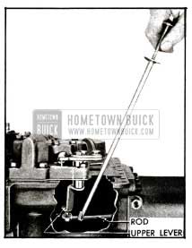
- Disconnect valve operating rod from valve operating lever (upper) by placing screwdriver on rod close to lever and exerting slight pressure. A spring loaded socket on rod engages a ball stud on lever. See figure 5-28.
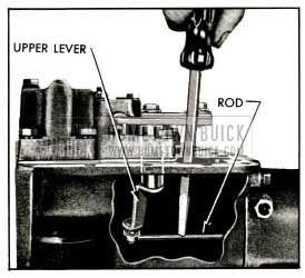
1955 Buick Disconnecting Valve Operating Rod from Upper Lever
- Slightly loosen all valve and servo body attaching bolts, then remove bolts and lockwashers. Do not loosen or remove the slotted safety nuts on valve-to-servo body studs.
- Lightly pry upward on the assembly to free the gasket between servo body and 1955 Buick Dynaflow transmission case. Push shift control valve and lower operating lever inward to align the lower lever with opening in transmission case, then remove the assembly. See figure 5-29.
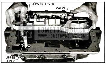
1955 Buick Removing Valve and Servo Body Assembly
CAUTION: Do not grasp slotted end of control valve because sharp edges may cut hand. Remove gasket and check for indication of oil leakage.
- Remove the reverse band operating strut by extending fingers through the adjustment hole to prevent strut from falling into 1955 Buick Dynaflow transmission case then release the strut by raising the operating lever. See figure 5-30.
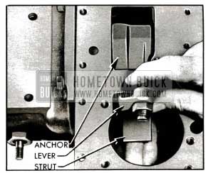
1955 Buick Removing Reverse Band Operating Strut
- See paragraph 5-17 for overhaul of valve and servo bodies and oil pan, and paragraph 5-23 (g) for installation of these units.
Removal of 1955 Buick Dynaflow Reaction Shaft Flange, Oil Pump, Accumulators, and Clutch
NOTE: The 1955 Buick Dynaflow converter and bell housing (subpar. b) and the valve and servo body (subpar. c) must be removed.
- Remove retaining ring from groove in input shaft.
- Loosen; but do not remove caps on both accumulators.
- Remove the bolts which attach the accumulators and the oil pump cover but do not remove the stud nuts which attach these parts. See figure 5-31.
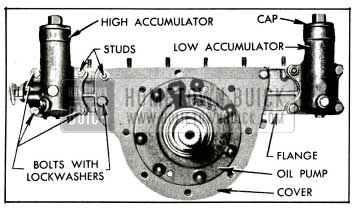
1955 Buick Accumulator Body and Reaction Shaft Flange Attaching Screws
- Tap very lightly on rear of accumulator bodies with fiber mallet to loosen reaction shaft flange, then remove the assembly and gasket. Leave input shaft in place in transmission.
- Check reaction flange gasket for good imprint and freedom from damage which would cause an oil leak at this point.
- Pull the input shaft and clutch hub front thrust washer from the clutch assembly, then remove the clutch assembly. See figure 5-32.
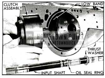
1955 Buick Removal of Clutch Assembly
- Compress the low band with the operating lever while applying Band Clip J 2595 across the strut flanges of the band. Release the lever and remove low hand, then remove the struts which will drop into case. See figure 5-33.
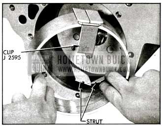
1955 Buick Removing Band with Clip J 2595
- Remove the low band operating lever by threading a 1/4,”-20 cap screw into the lever shaft and pulling shaft out of case.
- See paragraph 5-18 for overhaul of front oil pump and reaction flange, paragraph 5-19 for overhaul of accumulators, paragraph 5-20 for overhaul of clutch, and paragraph 5-23 ( e, f) for installation of these units.
Removal of 1955 Buick Dynaflow Torque Ball and Universal Joint
NOTE: None of the preceding operations are required for removal of torque ball and universal joint.
- Remove the 1955 Buick Dynaflow torque ball rubber boot.
- Remove attaching bolts, then remove the torque ball with inner and outer retainers, and all paper shims. See figure 5-34. Do not lose the paper shims which govern the adjustment of torque ball.
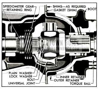
1955 Buick Torque Ball and Universal Joint
- Remove speedometer driven gear and sleeve assembly.
- Place 1955 Buick Dynaflow transmission shift lever on cross shaft and push lever forward while turning universal joint until the locking pawl engages the parking lock ratchet wheel.
- Remove universal joint bolt, lockwasher and flat washer, using a 3/4″ socket wrench and extension.
- Pull universal joint from output shaft, using Universal Joint Puller J 682-A if joint cannot be removed by hand. See figure 4-31.
- Remove 1955 Buick Dynaflow transmission shift lever.
- See paragraph 5-23 (h) for installation of universal joint and torque ball.
Removal of 1955 Buick Dynaflow Rear Bearing Retainer and Parking Lock Ratchet Wheel
NOTE: Only the torque ball and universal joint (subpar. f) and oil pan need be removed.
- Disconnect valve operating rod from upper operating lever if not previously done. See figure 5-28.
- Remove universal joint retaining ring from output shaft, using hammer and large screwdriver as shown in figure 5-35.
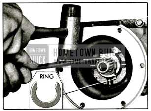
1955 Buick Removing Universal Joint Retaining Ring
Use care to avoid nicking output shaft as nicks will damage rear bearing retainer bushing during removal of retainer.
- Remove 1955 Buick Dynaflow retaining bolts, then remove rear bearing retainer and gasket. Check gasket for evidence of oil leakage.
- Using snap ring pliers, remove ratchet wheel outer retaining ring, slide wheel from output shaft, and remove inner retaining ring. See figure 5-36.
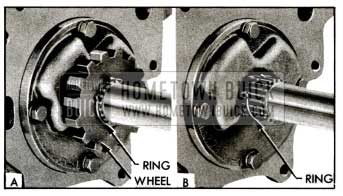
1955 Buick Removing Ratchet Wheel Retaining Ring
- See paragraph 5-21 for overhaul of rear bearing retainer and paragraph 5-23 (d) for installation.
Removal of 1955 Buick Dynaflow Rear Oil Pump and Lubrication Oil Pressure Regulator Valve
NOTE: 1955 Buick Dynaflow Rear bearing retainer (subpar. f) must be removed.
- Remove retaining bolts then remove pump body, which contains the pump gears.
- Remove the drive key, then use pointed tool to remove the rubber cushion which is located under drive key in the output shaft.
- Remove the rear pump plate and gasket if they can be removed from the case without prying. If plate is stuck, it can be tapped out after removal .of the planetary gear set. Check gasket for indication of oil leakage.
- Remove the lubrication oil pressure regulator valve seat from transmission case, using the locally prepared drag link socket shown in figure 5-37. Remove valve and spring.
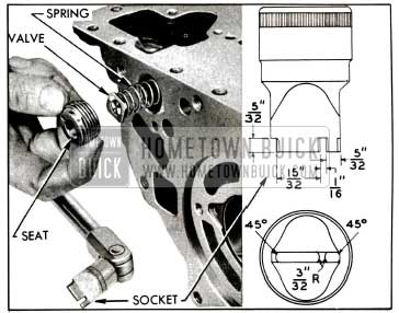
1955 Buick Removal of lubrication Oil Pressure Regulator Valve
- See paragraph 5-18 for inspection of rear oil pump and paragraph 5-23 (c) for installation.
Removal of 1955 Buick Dynaflow Planetary Gear Set – Reverse Ring Gear and Reverse Band
NOTE: All of the proceeding operations must be performed before removal of planetary gear set.
- Remove 1955 Buick Dynaflow planetary gear set through front of case. See figure 5-38.
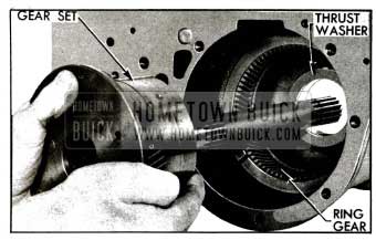
1955 Buick Removing Planetary Gear Set
- Remove the reverse ring gear, also the planet carrier thrust washer if this did not come out with planetary gear set.
- If rear oil pump plate and gasket were not previously removed, tap them out with hammer handle from front side of case.
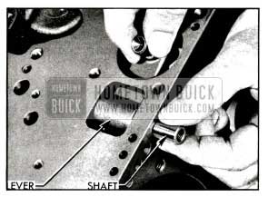
- Thread a 1/4″-20 bolt into the reverse band anchor shaft to pull it from transmission case; then remove the operating lever. Rotate the reverse band until the anchor can be disengaged, then remove this part. See figure 5-39.
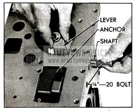
1955 Buick Removing Reverse Band Operating Lever and Shaft
- Compress ends of reverse band and apply Band Installing Clip J 2595 across the strut flanges, then remove band.
- Remove the reverse ring gear thrust washer from case.
- See paragraph 5-22 for overhaul of planetary gear set and paragraph 5-23 (b) for installation.
5-15 DISASSEMBLY, INSPECTION, ASSEMBLY OF 1955 BUICK DYNAFLOW TORQUE CONVERTER UNIT
Disassembly of 1955 Buick Dynaflow Twin Turbine and Sun Gear
- Pry retaining ring out of groove in first turbine, insert screwdriver in a hole in the disk and lift disk and hub assembly out of first turbine. See figure 5-40.
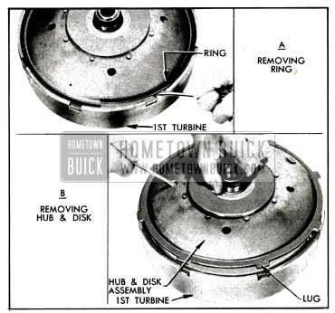
1955 Buick Removing Disk and Hub Assembly
- Lift the 1955 Buick Dynaflow second turbine and carrier assembly out of first turbine.
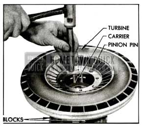
- Remove four bolts with lockwashers and the pinion pin lock plate from second turbine. See figure 5-41. It is not necessary to remove the turbine from carrier at this time.
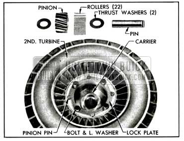
1955 Buick Second Turbine Parts
- Remove pins, then remove the four planet pinions and thrust washers from turbine carrier. Remove bearing rollers (22) from each pinion. See figure 5-41.
- Remove thrust washer (with tangs) from front face of sun gear and carefully tap the cupped thrust washer from other end.
- Remove the sprag (free wheel clutch) from inside of sun gear. See figure 5-42.
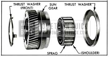
1955 Buick Sun Gear Parts
Disassembly of 1955 Buick Dynaflow Variable Pitch Stator
- Remove stator thrust washer and selective spacers from rear side of stator, remove Tool J 5806, then remove free wheel rollers and springs from the cam.
- Pry the retaining ring from groove in stator blade rear carrier, and remove free wheel cam and three driving keys. See figure 5-43.
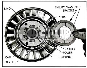
1955 Buick Parts in Rear Side of Stator
- Use Screwdriver J 5826 to remove the stator blade front carrier screws and lockwashers, then remove front carrier which is also held to rear carrier by two dowels. See figure 5-44.
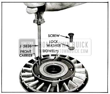
1955 Buick Removing Front Carrier Screws
- Remove retaining ring and thrust washer from hub of stator piston, then remove stator blade carrier ring and all stator blades from rear carrier. See figure 5-45.
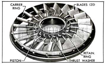
1955 Buick Front Side of Stator, with Carrier Removed
- Remove stator piston with sealing ring from rear carrier.
Inspection of 1955 Buick Dynaflow Torque Converter Parts
- Wash all parts in clean solvent and dry thoroughly.
- Inspect 1955 Buick Dynaflow converter pump hub for scores and for wear caused by the front pump seal. If pump is suspected of leaking oil it may be tested as described in subparagraph d, below.
- Inspect converter pump and turbines for cracked or damaged vanes.
- Inspect turbine carrier, planetary gear teeth, thrust washers, bushings and related bearing surfaces for excessive wear, scoring, or other damage.
- Inspect stator free wheel rollers and cam for nicks or burrs, which should be removed with an Arkansas stone and polished with crocus cloth. Discard any roller springs that are damaged or distorted.
- Inspect 1955 Buick Dynaflow stator blades for distortion, cracks, loose on cranks, or other damage.
- Inspect piston oil seal ring and bore of blade carrier for scoring or wear. If bushings in carrier are worn they should be replaced, using Installer J 5913 to properly locate new bushings. See figure 5-46.
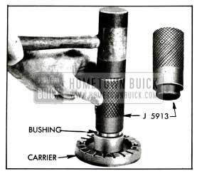
1955 Buick lnstalling Bushing in Blade Carrier
- If second turbine or the carrier must be replaced, use care in separating them to avoid damage to the good part.
With second turbine suitably supported, tap carrier free of counterbore in turbine, using hammer and a hardwood dowel or other soft punch. Do not drive against surface of thrust boss in carrier. See figure 5-47.
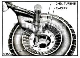
1955 Buick Removing Carrier from Turbine
Testing 1955 Buick Dynaflow Converter Pump for Oil Leakage
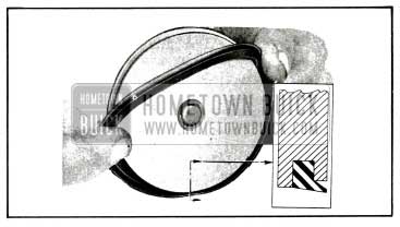
- Prepare a plate with rubber washer to close the opening in converter pump hub, as shown in figure 5-48.
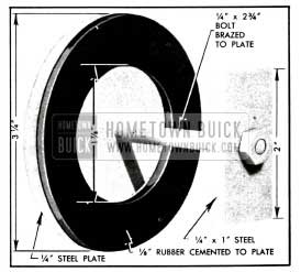
1955 Buick Plate and Washer for Pump Test
The bolt head should be brazed to the plate to seal the bolt hole, and the 1/8″ thick rubber washer should be cemented to the plate.
- Install plate with washer over inside surface of pump hub (fig. 5-49), then install pump cover with seal and tighten all bolts to 25-30 ft. lbs. torque in sequence shown in figure 5-105.
- Install one drain plug, and install a Barrett fitting No. 365 in other drain hole. Tighten parts securely. See figure 5-49.
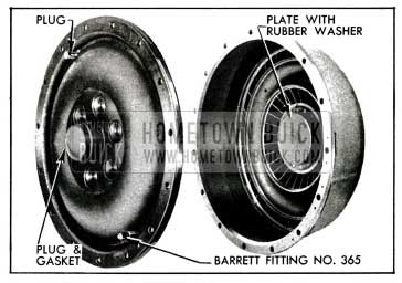
1955 Buick Plate and Plugs Installed in Pump and Cover
- Attach air hose to Barrett fitting, fill pump with compressed air at 80 to 100 lbs./sq. in. and submerge pump in water tank. Air bubbles will appear at any point where oil leakage exists.
CAUTION: After a pump cover seal is used in this test it should not be used when rebuilding transmission.
Assembly of 1955 Buick Dynaflow Variable Pitch Stator
- Install 1955 Buick Dynaflow oil sealing ring in stator piston, then tilt piston slightly to install it in bore of rear carrier, placing piston so that the hub extends through flanged end of carrier.
- Mount piston and carrier on a suitable support (such as ring of Spring Compressor J 2590) so that piston is held up against flange of carrier.
- With stator blade carrier ring resting on bench with holes upward, insert stator blades with concave sides upward and cranks toward center of ring. Blades should be in the nearly closed position, as shown in figure 5-45.
- Carefully place the carrier ring with blades in position on the rear carrier so that all cranks engage the grooves in carrier. See figure 5-45.
- Install thrust washer over cranks and install retaining ring in groove of piston hub. See figure 5-45.
- Place front carrier over rear carrier so that screw holes are aligned when dowels enter their holes, then install screws with countersunk external tooth lockwashers. See figure 5-44.
- After screws are turned down snug with Screwdriver J 5826, check stator blades and piston for smooth operation. Blades should move throughout range without binding; if they do not, check for misalignment of cranks in carrier grooves. Tighten screws firmly and make sure that blades still operate freely.
- Install the free wheel cam with three driving keys and retaining ring in the rear carrier. See figure 5-43.
- Check free wheel springs and alter lengths as necessary to assure equal length of all springs. Place free wheel rollers and springs in cam, with rollers at rounded ends of cam recesses. See figure 5-43.
- Install Tool J 5806 through free wheel rollers by turning it slightly clockwise, so that flat end of tool is flush with rollers and cam.
- Make certain that surfaces of cam, spacers, and thrust washer are free of grease and dirt, then install spacers and washer with tangs of washer extending through holes in spacers and cam.
Assembly of 1955 Buick Dynaflow Sun Gear and Twin Turbine
- Install sprag in bore of sun gear with shouldered end outward (fig. 5-42) then carefully press the cupped thrust washer over end of gear. Use a smooth flat plate or block of wood to press against washer to avoid damaging its surface.
- Install tanged thrust washer on opposite end of sun gear.
- If second turbine was separated from the carrier, make certain that counterbored recess in turbine and mating surfaces of carrier are clean and free of burrs, and apply a film of oil to these surfaces.
- Support the carrier on suitable blocks, install several pinion pins to serve as pilots, then place turbine in position so that carrier is squarely started into recess in turbine.
- Use a hammer and hardwood dowel or other soft punch to tap the turbine down over the carrier. Avoid distortion of turbine by using light blows applied midway between holes and alternated from side to side to keep parts square with each other. See figure 5-50.
1955 Buick Installing Turbine on Carrier
NOTE: If 1955 Buick Dynaflow turbine cannot be assembled on carrier with moderate force, remove it and check for burrs in counterbored recess.
- With turbine and carrier supported on wood blocks, hub side down, assemble and install the four pinions as follows:
- Place planet pinion on a thrust washer, install 22 needle bearing rollers in pinion and place a thrust washer on top of pinion. NOTE: A loading tool made locally of steel rod 3/8″ in diameter by 11/16″long will simplify loading and installation of pinion. See figure 5-51.
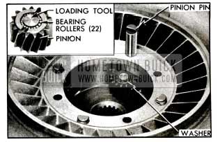
1955 Buick lnstalling Pinion In Carrier
- Place assembled pinion in carrier and install a pinion pin with notched end up. After loading tool is pushed out of carrier, slide a block under pinion pin to hold it in place. Turn all pins so that notches face center of carrier. See figure 5-51.
- Install pinion pin lock plate so that it enters the notches of all pins, then install the four turbine-to-carrier bolts with lockwashers. See figure 5-41.
- Place second turbine and carrier assembly in first turbine, then install the first turbine disk and hub assembly over the second turbine. See figure 5-40, view B.
- Rotate disk until the ring gear meshes with the carrier pinions, then align driving lugs on disk with notches in first turbine and push the assembly all the way down into turbine.
- Note that the turbine disk retaining ring is “dished”. Place the ring in position with the “dish” upward so that the inner edge will bear firmly against the disk when the ring is engaged in the groove in first turbine. See figure 5-52.
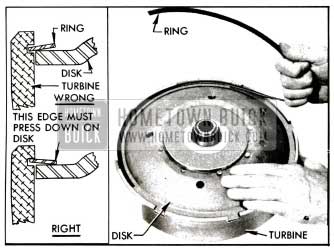
1955 Buick lnstalling Disk Retaining Ring
- Start one end of ring into groove in turbine, then twist the ring upward as shown in figure 5-52 to lay the ring flat on the disk so that it can be progressively entered into the groove all the way around.
- Make certain that the ring is fully seated in the groove and that inner edge bears against the turbine disk. Tap inner edge down against disk if it has raised up.
5-16 ALIGNMENT OF 1955 BUICK DYNAFLOW CONVERTER PUMP AND BELL HOUSING
1955 Buick Dynaflow Converter oil leaks, front oil pump body leaks, front oil pump noise, and excessive wear of front oil pump bushing and oil seal may be caused by: (1) Excessive run-out of flywheel face (2) Excessive run-out of converter pump hub (3) Misalignment of bell housing.
When any of these conditions are encountered and there is any doubt as to their true cause, check the flywheel, converter pump and bell housing as follows:
- Check run-out of flywheel face as described in paragraph 2-26 and make required corrections before proceeding further.
- Install converter pump and cover on flywheel and tighten mounting bolts to 25-30 ft. lbs. torque. Install bell housing on crankcase.
- Prepare a special dial indicator clamp by welding a piece of 5/16″ x 3″ drill rod to a 1″ C-clamp. Use the special clamp and Sleeve KM0-30-K to mount Dial Indicator KM0-30-B so that indicator stem bears against the pump hub as shown in figure 5-53.
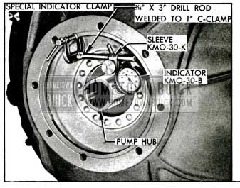
1955 Buick Checking Run-Out of Converter Pump Hub
- Turn 1955 Buick Dynaflow flywheel and note indicator reading. Run-out of pump hub should not exceed .012″. If run-out exceeds .012″, replace pump and recheck run-out.
- Attach the special dial indicator clamp to the oil pump driving lug on rear end of converter pump hub. CAUTION: Do not clamp to bearing surface of hub. Mount Dial Indicator KM0-30-B to bear against rear face of bell housing at a radius of 3 3/4″. See figure 5-54.
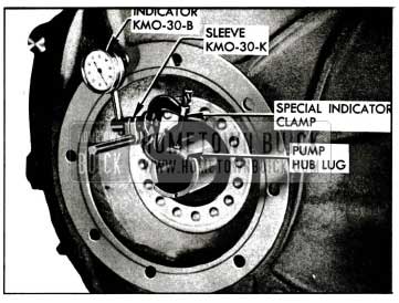
1955 Buick Checking Run-Out of Rear Face of Bell Housing
- Turn flywheel, making sure that crankshaft end thrust is held in one direction, and note run-out of bell housing face as shown by dial indicator. Run-out should not exceed .005″.
- If run-out of bell housing face exceeds .005″, cement paper shims of proper thickness to rear face of crankcase to bring run-out of housing face to .005″ or less, with all bolts securely tightened.
- Mount dial indicator and Hole Attachment KM0-30-F to bear against inner edge of pilot hole in bell housing. See figure 5-55. Runout of pilot hole should not exceed .004″.
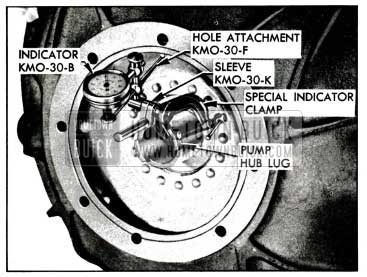
1955 Buick Checking Run-Out of Bell Housing Pilot Hole
- If run-out of pilot hole exceeds .004″, remove bell housing, remove the two dowels, and reinstall bell housing, leaving bolts just loose enough to permit shifting housing by tapping with a lead hammer.
- Set up dial indicator as shown in figure 5-55 and bring pilot hole of bell housing within .004″ run-out by tapping in required direction with lead hammer. If it is not possible to move housing far enough, remove housing and drill bolt holes with %” drill. When bell housing is placed so that pilot hole run-out is .004″ or less, tighten all bolts securely.
- Ream the two dowel holes through housing and crankcase, using Ratchet J 808-6 with tapered Reamer J 2548-3 ( 17/32″) until this reamer bottoms in hole, then finish with bottoming Reamer J 4710-6 to provide full size to bottom of hole.
- Remove bell housing and install oversize dowels J 808-5 in crankcase.
5-17 DISASSEMBLY, INSPECTION, ASSEMBLY OF 1955 BUICK DYNAFLOW VALVE AND SERVO BODIES
Disassembly of 1955 Buick Dynaflow Valve Body
CAUTION: The valves have sharp edges which can cut fingers if improperly handled. As these parts are removed wrap them separately in clean cloths to avoid damage through contact with other parts.
- Remove safety nuts and washers from studs, then lift the valve body and gasket from servo body. Remove shift control valve from valve body. Check gasket for evidence of oil leakage.
- Remove the rear pump delivery check valve and spring from servo body to avoid losing these nuts.
- Remove the large pressure regulator valve plug from valve body, using care because of the heavy spring pressure behind the plug. Remove the two springs and spring seat. See figure 5-59.
- Remove the small valve plug and remove the pressure regulator valve from body.
- Remove valve body plate and gasket, then remove the front pump delivery check valve and spring. Check gasket for evidence of oil leakage.
Disassembly of 1955 Buick Dynaflow Servo Body
- Remove nut and lockwasher which attaches the lower valve operating lever and linkage adjusting lever to the upper lever shaft and remove levers.
- Remove servo body spacer plate attaching screw at reverse servo which is in line with the low servo then place a 1″x1″x13″ wooden block across the low and reverse servo spring seats. See figure 5-56.
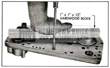
1955 Buick Removing Servo Body Spacer Plate
- Hold the block down firmly while removing the remaining spacer plate attaching screws, then carefully release pressure on block to allow servo springs to expand. This operation must be done carefully to avoid springing the spacer plate or letting the servo springs fly out. Remove spacer plate and gasket. Check gasket for indication of oil leakage.
- Remove reverse and low servo piston spring seats, springs and pistons. Remove check ball from reverse servo feed channel. See figure 5-58.
Cleaning and Inspection of 1955 Buick Dynaflow Valve and Servo Parts
- Thoroughly wash valve and servo bodies with clean solvent, dry and blow out all passages with air. Wash other parts and dry thoroughly.
- Carefully inspect bodies for cracks, damage to gasket surfaces, scores in piston and valve cylinders, or other damage which would render these parts unfit for use.
- Inspect surfaces and shoulders of shift control valve and pressure regulator valve. Surfaces must be free of nicks, scores, or deep scratches. A valve must be replaced if the sharp edges of shoulders are marred or rounded because such conditions will permit fine particles of foreign matter to work in between the part and the body and cause sticking. Check valves on surface plate and replace if bent.
- Worn or damaged piston seals should be replaced. When a new seal is installed on a piston make sure that the lip fits over the smaller diameter land. See figure 5-57.
1955 Buick lnstallation of Servo Piston Seal
- Thoroughly clean oil screen and check for any cracks or holes which would allow dirt to pass through.
Assembly of 1955 Buick Dynaflow Servo Body
- Oil and install the low and reverse servo piston assemblies in servo body. To avoid curling or damaging edge of piston seal, start each piston into cylinder at an angle then turn piston slightly as it is straightened and pushed into cylinder. See figure 5-58. Check pistons for free movement in cylinders.
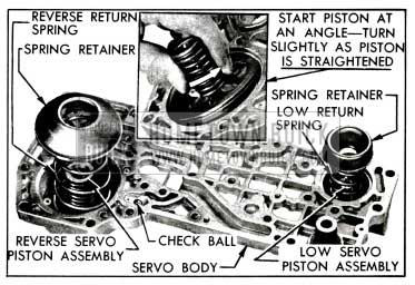
1955 Buick Parts Installed in Servo Body
- Install the small return spring with small end against the low servo piston. Install the large return spring with the large end against the reverse servo piston. Place spring seats on upper ends of both springs. See figure 5-58.
- Place check ball in reverse servo feed channel. See figure 5-58.
- Install a new spacer plate gasket and place spacer plate in position over spring seats. Place a 1″x1″x13″ wooden block across spring seats to compress the springs while installing the spacer plate screws (fig. 5-56). Tighten screws uniformly to avoid distorting spacer plate.
- Insert valve operating upper lever shaft through bearing in servo body. With upper lever pointing toward the reserve servo, place lower lever with linkage adjusting lever on shaft so that forked end of lower lever points to the low servo, then install lockwasher and nut.
Assembly of 1955 Buick Dynaflow Valve Body
- Place 1955 Buick Dynaflow front pump delivery check valve spring in body with large end down and place check valve on spring with ridged side up. See figure 5-59.
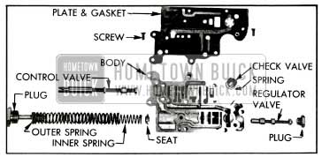
1955 Buick Valve Body Disassembled
- Install valve body plate and a new gasket, making sure that check valve is seated against plate and is not caught under gasket.
- Place the pressure regulator spring seat on the inner spring, then install spring seat, inner and outer springs and the large plug in valve body. Tighten plug to 20-25 ft. lbs. torque.
- See that oil orifice in pressure regulator valve end land is clear, then install valve with this land outward. Install plug and tighten to 20-25 ft. lbs. torque.
- Install shift control valve with slotted end on same end of valve body as the large pressure regulator plug.
- Install rear pump delivery check valve in its seat in servo body, ridged face inward, and place valve spring on valve with large end up.
- Install a new gasket and the valve body on servo body, using care to keep pump delivery check valve spring below the gasket, then install plain washers and safety nuts on two studs adjacent to the control valve. Tighten stud nuts evenly to 11-15 ft. lbs. torque.
- See paragraph 5-23 (g) for installation of valve and servo bodies.
5-18 DISASSEMBLY, INSPECTION, ASSEMBLY OF 1955 BUICK REACTION SHAFT FLANGE AND OIL PUMPS
Disassembly of 1955 Buick Dynaflow Front Oil Pump and Reaction Shaft Flange
- Remove high and low accumulators from reaction shaft flange, using care to prevent the retaining pin and check ball from dropping out of high accumulator and being lost. Check gaskets for indication of oil leakage.
- Inspect the input shaft bearing in front end of reaction shaft. If bearing is damaged or excessively worn, remove outer retaining ring and then remove the bearing, using Remover J 5822 installed on Remover J 1436. See figure 5-60.
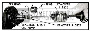
1955 Buick Removing Input Shaft Bearing
Oil pump must be in place to support the reaction flange during bearing removal.
If inner retaining ring remained in place in shaft make sure it is firmly seated in its groove; otherwise replace it.
- Check front oil pump bolts to make sure they are tight. Loose bolts would be the cause of oil leakage around the pump. Remove front oil pump body and gears, tapping body lightly with mallet to free it, if necessary.
- Remove front oil pump cover and gasket from reaction shaft flange, and check gasket for evidence of oil leakage.
- If the check ball located in clutch feed passage of reaction shaft flange is free to drop out, remove ball to avoid loss in handling parts. Do not remove if securely retained by peened edge of hole.
Cleaning and Inspection of 1955 Buick Dynaflow Front and Rear Oil Pumps
- Wash pump parts in clean solvent and dry thoroughly.
- Check mounting faces of pump bodies, gears, front pump cover and rear pump cover plate for excessive wear.
- Inspect front oil pump bushing. If bushing is loose or excessively worn replace the pump assembly.
- If front oil pump bushing is loose or excessively worn, or pump was noisy always check for flywheel run-out, converter pump hub run-out, and misalignment of bell housing as described in. paragraph 5-16.
- Inspect the front pump oil seal but replace it only if there is definite evidence of leakage or damage. Drive out defective seal with a punch. Lightly coat outside of new seal with No. 3 Permatex, start seal squarely into pump body with deep groove in seal retainer outward and tap into place with hardwood block and mallet. Wipe off excess Permatex.
- Place a straight edge on face of pump body and check side clearance of gears with feeler gauge. See figure 5-61. Clearance should be .001″ to .0025″ on front pump and .001″ to .002″ on rear pump.
1955 Buick Checking Side Clearance of Gears in Pump Body
- Insert feeler gauge between crescent and driven gear to check clearance, which should be .005″ to .009″ on front pump and .0045″ to .007″ on rear pump. See figure 5-62, view A.
1955 Buick Checking Clearance Between Crescent and Gears
- Insert feeler gauge between crescent and driving gear to check clearance, which should be .010″ to .016″ on front pump and .006″ to .012″ on rear pump. See figure 5-62, view B.
- Check front pump cover and rear pump cover plate for depth of wear caused by the gears. Replace the part if depth of wear exceeds .001″ or surface is scored.
Cleaning and Inspection of 1955 Buick Dynaflow Reaction Shaft Flange
- Wash flange in clean solvent, dry thoroughly and blow out all passages with air.
- Inspect surfaces of 1955 Buick Dynaflow reaction shaft flange and transmission case for nicks or burrs and remove with mill file.
- Inspect race for clutch drum roller bearing on rear end of reaction shaft. If this bearing surface is worn excessively or scored, replace reaction shaft flange.
NOTE: If 1955 Buick Dynaflow reaction shaft flange is replaced, stamp transmission identification number in lower edge of new part in same place as on original flange. See figure 5-l.
- Check all studs for tightness and replace any with damaged threads. If stud threads are stripped in reaction shaft flange, it will be necessary to tap out the hole for installation of step studs which are available. The 5/16″-18 step studs have a 3/8″-16 thread on the flange end.
- Inspect the oil sealing rings on hub of reaction shaft flange and replace if damaged in any way.
Assembly of 1955 Buick Dynaflow Front Oil Pump and Reaction Shaft Flange
- If old input shaft bearing was removed, first make sure that inner retaining ring is firmly seated in groove in reaction shaft, then install a new bearing using Installer J 5816. Support shaft on wooden block to avoid damage and drive bearing into place with light hammer until shoulder of tool contacts reaction shaft. See figure 5-63. Install outer retaining ring.
1955 Buick lnstalling Input Shaft Bearing
- Install check ball in clutch feed passage if ball was removed, then install a new gasket and the pump cover on reaction shaft flange.
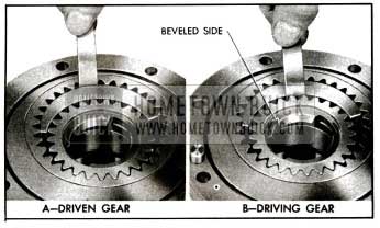
- Lubricate and install gears in front pump body. The driving gear must be installed with the beveled side outward so that this side will be against the cover when pump is installed. See figure 5-62. Reversing this gear in pump body will result in severe damage to the transmission.
- Install oil pump on cover so that the two dowel pins and the bolt holes match holes in cover, then install bolts with lockwashers. Tighten bolts to approximately 5 ft. lbs. torque in the sequence shown in figure 5-64 and then tighten in same sequence to 25-30 ft. lbs. Bend a tang of each lockwasher up against fiat of bolt head. Tighten cover attaching stud nut to 25-30 ft. lbs. torque.
1955 Buick Front Oil Pump Tightening Sequence
- See paragraph 5-23 (f) for installation of front pump and reaction shaft flange assembly.
5-19 DISASSEMBLY, INSPECTION, ASSEMBLY OF 1955 BUICK DYNAFLOW ACCUMULATORS
- Remove retaining pin and check ball from high accumulator body. The low accumulator does not have the check ball.
- Remove the pipe plug, cap, gasket, spring (2 in Low) and piston from accumulator body. Keep parts separated so that same parts will be reinstalled in same body. See figure 5-65.
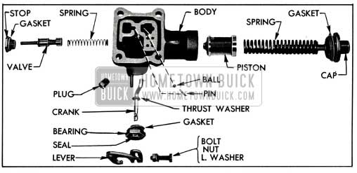
1955 Buick High Accumulator-Disassembled
- On high accumulator only, remove clamp bolt, lever, bearing with seal, gasket, thrust washer and control valve crank from accumulator body, then remove valve stop with gasket, control valve and spring. See figure 5-65.
- Wash accumulator parts in clean solvent, dry thoroughly, and blow out all passages with air. Examine all parts of each accumulator for excessive wear, scoring, or other damage.
- Remove any nicks or burrs from pistons or valve with an Arkansas stone; however, do not round the sharp edges of lands on pistons and valves. If the sharp edges are marred or rounded foreign particles may wedge between the part and the body and cause sticking.
- With parts clean and dry, install pistons and check for free sliding as body is tipped back and forth.
- Check mounting surface of body with a straight edge. If surface is uneven it may be trued up by moving body in a circular motion over emery cloth placed on a surface plate. Thoroughly wash body to remove all traces of emery.
- If the body or piston is worn or damaged, or piston does not slide freely in body after all burrs are removed, replace accumulator assembly. The body and piston are not furnished separately for service replacement.
- Lubricate each piston and install it in the accumulator body from which it was removed. Start piston squarely into body; do not tap or force it into body.
- Install proper piston springs in each body. The high accumulator uses one heavy spring approximately 4 5/16″ long. The low accumulator uses one shorter heavy spring and one inner spring. Install caps with new gaskets but these will be tightened later-do not clamp accumulator in vise to tighten ca. p.
- On high accumulator only, install spring, control valve and stop, then install crank with thrust washer, bearing with new gasket and seal (grooved side inward), operating lever and clamp bolt. See figure 5-65.
- Adjust operating lever on crank so that lever contacts its stop and the crank contacts the valve without depressing the spring, then tighten the clamp bolt. See figure 5-66.
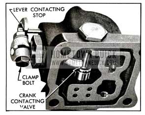
1955 Buick Valve Operating Lever Adjustment
- Install pipe plugs in both accumulator bodies and install check ball and retaining pin in the high accumulator body. See figure 5-65.
- See paragraph 5-23 (f) for installation of accumulators.
5-20 DISASSEMBLY, INSPECTION ASSEMBLY OF 1955 BUICK DYNAFLOW CLUTCH
Disassembly of 1955 Buick Dynaflow Clutch
- Remove 1955 Buick Dynaflow reaction gear flange retainer ring with screwdriver and remove the 3 flange driving keys with pointed tool. See figure 5-67.
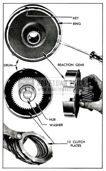
1955 Buick Removal of Reaction Gear, Hub, and Plates
- Remove the low range reaction gear, thrust washer, clutch hub, and 10 clutch plates from drum. See figure 5-67.
- Install 1955 Buick Dynaflow Clutch Spring Compressor J 2590 in assembled drum, placing the slot in compressor ring over the ends of spring seat retaining ring. Compress clutch spring sufficiently to remove the retaining ring. See figure 5-68.
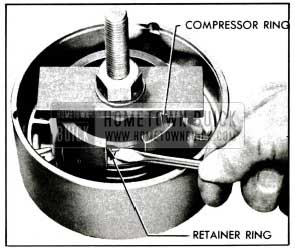
1955 Buick Using Clutch Spring Compressor J 2590
- Release pressure on clutch spring, making sure that spring seat does not engage retaining ring groove in drum, then remove spring compressor, spring seat and spring.
- Remove piston from drum. It may be necessary to rap the open end of drum against a block of wood to remove the piston.
Cleaning and Inspection of 1955 Buick Dynaflow Clutch and Input Shaft
- Wash all parts in clean solvent and dry thoroughly. Use only gasoline or kerosene to clean clutch plates and bands-DO NOT use any chemical degreasers or other commercial solvents.
- Inspect all clutch plates and replace any that are scored, burned, warped or worn excessively. Check fit of any new internally splined plates on clutch hub to make certain that they slide freely on hub. Tight plates will prevent full disengagement of the clutch.
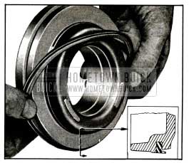
- Inspect drum for cracks or scores. Inspect oil sealing ring on hub of drum and replace it if damaged. To remove ring, apply finger pressure at points indicated by arrows in figure 5-69, in order to unlock the ends by depressing one end and raising the other. Use the same method to lock the ends during installation of new ring.
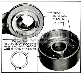
1955 Buick Removal of Clutch Piston and Oil Sealing Ring
- Inspect 1955 Buick Dynaflow clutch piston outer seal and replace if hardened, broken, or has turned edges. Install new seal with lip extending over the smaller diameter land of piston. See figure 5-70.
1955 Buick Replacement of Clutch Piston Outer Seal
- Make sure that small bleed hole in drum is open and that check ball is staked in place but free to move in recess. If needle bearing in drum is excessively worn or scored carefully remove it and install a new one, using Installer J 5191 shown in figure 8-27. This tool will locate bearing flush with shoulder in drum. Place numbered end of bearing, which is hardened, toward shoulder of tool to avoid distortion of cage.
- Inspect the low band. If band lining is worn smooth so that the grooves are gone replace the band.
- Inspect input shaft splines, bearing surfaces and oil seal rings. Replace either part if excessively worn or damaged.
Assembly of 1955 Buick Dynaflow Clutch
- Apply light oil to the piston outer seal and the inside of drum, then install piston carefully to avoid distorting or turning the lip of seal. When piston is fully installed in drum, the top of piston will be approximately flush with the shoulder on inside of drum.
- Place clutch spring in piston and place spring seat and seat retaining ring on spring. Install Clutch Spring Compressor J 2590 (fig. 4-68) and compress spring until the retaining ring can be snapped into the groove in hub of drum, then remove the spring compressor.
- Place reaction gear on bench with flange upward, then install clutch hub thrust washer and clutch hub over the hub of reaction gear, with open end of clutch hub facing up. See figure 5-71.
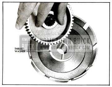
1955 Buick lnstalling Thrust Washer and Clutch Hub in Reaction Gear
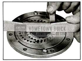
- Separate the internally splined (faced) clutch plates from the externally splined (plain steel) clutch plates. Internally splined plates are flat and may be installed in either direction. Externally splined plates are “dished” and all these plates must be installed with the “dish” in the same direction; however, the “dish” may be either up or down. Check each plate for “dish” with a straight edge, figure 5-72, and stack plates so that all are “dished” in same direction.
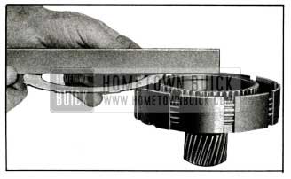
1955 Buick Checking Dished Side of Externally Splined Clutch Plate
- Install an internally splined clutch plate over clutch hub, next to gear flange, then install an externally splined plate. Alternately install the remaining plates, making sure that externally splined plates are “dished” in same direction. If properly installed, the top plate will be externally splined.
- Place the drum and clutch piston assembly over the reaction gear flange so that the driving key recesses in drum and flange are approximately aligned. See figure 5-73, view A. Press the drum evenly into place over the reaction gear flange.
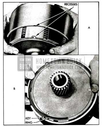
1955 Buick lnstalling Drum Over the Reaction Flange Gear
- Complete the alignment of driving key recesses by tapping the reaction gear flange, then install the 3 driving keys and the reaction gear flange retainer ring. See figure 5-73, view B.
- See paragraph 5-23 (e) for installation of clutch and input shaft.
5-21 DISASSEMBLY, INSPECTION, ASSEMBLY OF 1955 BUICK BEARING RETAINER, TORQUE BALL, AND UNIVERSAL JOINT
Disassembly of 1955 Buick Dynaflow Rear Bearing Retainer
- Remove spring from detent roller lever and support inside the rear bearing retainer, remove adjusting lever on outside of retainer, then remove lever and support assembly. See figure 5-74.
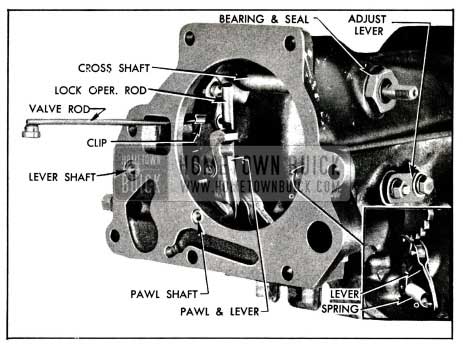
1955 Buick Parts in Rear Bearing Retainer
- Disconnect the parking lock operating rod from the cross shaft by unscrewing the rod end from cross shaft lever. The rod end is provided with a lockwasher. See figure 5-74.
- Push clip from valve operating rod to remove clip and rod from cross shaft.
- Screw a 1/4″-20 bolt into the parking lock operating lever shaft and the lock pawl shaft and pull these parts from bearing retainer, then remove the lock pawl and lever assembly. See figure 5-74.
- Remove cross shaft bearing, using a box wrench; a socket which does not fully engage bearing, or an end wrench will distort the bearing. Remove the cross shaft.
Cleaning and Inspection of 1955 Buick Dynaflow Rear Bearing Retainer Parts
- Wash all parts in clean solvent and dry thoroughly.
- Inspect valve operating cross shaft and bearing for excessive wear. Remove the rubber seal from bearing and discard it.
- Inspect the rear bearing retainer bushing for scoring or excessive wear. Insert the output shaft in bushing and check the clearance, which should be .001″ to .006″. Replace the bushing if it is excessively worn, using Bushing Remover and Replacer J 2997. See figure 5-75. Reaming to size is not required.
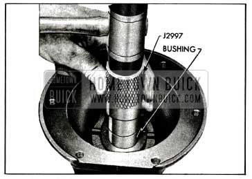
1955 Buick Bushing Remover and Replacer J 2997
- Inspect the parking lock pawl and ratchet wheel for cracks and worn teeth that would prevent positive locking.
- If any parking lock parts need to be replaced, remove the snap ring and separate the parts. When reassembled, the parts must be located as shown in figure 5-76.
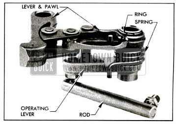
1955 Buick Parking Lock Pawl and Lever Assembly
Inspection and Repair of 1955 Buick Dynaflow Universal Joint and Torque Ball Parts
- Inspect 1955 Buick Dynaflow universal joint for wear and play between spider pins and the bushings. Allowable play is .002″ to .004″.
- Check fit of universal joint yokes on the output and propeller shafts. Allowable backlash of rear yoke on propeller shaft splines is .0005″ to .0045″. The front yoke must be a tight fit, rotatively, on output shaft to prevent “snap” when alternating car movement between forward and reverse.
- Inspect rear yoke of universal joint. Rear yoke and bushing in torque ball must be free of scores and not worn excessively; clearance between these parts should be .004″ to .006″.
- Clean and inspect spherical surfaces of torque ball and both retainers. If these are scored or pitted the parts should be replaced.
Assembly of 1955 Buick Dynaflow Rear Bearing Retainer
- Install the valve operating cross shaft, and cross shaft bearing. Install a new seal in the bearing, with grooved side facing inward.
- Install parking lock pawl and lever assembly in rear bearing retainer, then install the lock pawl shaft and operating lever shaft with tapped ends outward. See figure 5-74.
- Attach valve operating rod with retainer clip to cross shaft lever and snap clip into place over the rod.
- Connect parking lock operating rod to cross shaft lever, using a lockwasher on the threaded rod end.
- Install detent lever and support assembly with new seal in groove of shaft, then install linkage adjusting lever on shaft with nut and lockwasher.
- Attach adjusting lever to bearing retainer with bolt, plain washer and lockwasher, but do not tighten until the following detent adjustment is made.
- Temporarily install shift lever on cross shaft and shift parking pawl into Parking position. See figure 5-77.
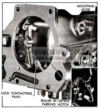
1955 Buick Shift Detent Adjustment
- Shift the linkage adjusting lever at slotted end until the pawl lock contacts the parking pawl, then tighten adjusting lever lock bolt, being certain to maintain contact between lock and pawl. See figure 5-77.
- Move shift lever back and forth to check detent adjustment. Parking lock must contact parking pawl when detent roller is in deepest portion of parking notch of detent lever and should break contact at same instant that detent roller starts to move toward neutral position.
- See paragraph 5-23 (d) for installation of rear bearing retainer.
5-22 DISASSEMBLY, INSPECTION ASSEMBLY OF 1955 BUICK PLANETARY GEAR SET AND TRANSMISSION CASE
Disassembly of 1955 Buick Dynaflow Planetary Gear Set
- Remove three planet carrier screws and special lockwashers, using a 7/32″ hexagon (Allen) wrench. See figure 5-78.
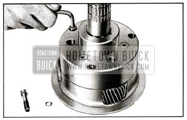
1955 Buick Removing Planet Carrier Screws
A used universal joint front yoke may be placed on output shaft and held with a bar while loosening the screws.
- Separate the front and rear ends of planet carrier by carefully tapping around the front flange while holding the unit clear of bench.
- Remove the sun gear rear thrust washer, which may be either on sun gear or stuck in rear end of carrier. Remove reverse sun gear. See figure 5-79.
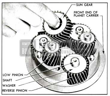
1955 Buick Removal of Sun Gear and Planet Pinions
- Remove the 3 low planet pinion assemblies, each consisting of a pinion, shaft, and bearing rollers retained at each end of pinion by steel thrust washers. See figure 5-79. A retaining ring snapped into a groove in shaft will hold the lower thrust washer in place as shaft is tapped out of carrier. The shaft is prevented from turning in carrier by a 3/32″ steel ball imbedded in end of shaft. Do not lose the steel ball.
- Remove the 3 reverse planet pinion assemblies which are similar to the low planet pinion assemblies and are removed in the same manner.
- Remove the thrust washers and shafts from pinions, then remove the bearing rollers. Note that the reverse planet pinions have a single set of rollers and the low planet pinions have two sets of rollers separated by a spacer. See figure 5-80.
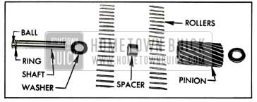
1955 Buick Low Planet Pinion, Disassembled
Cleaning and Inspection of 1955 Buick Dynaflow Planetary Gear Set
- Wash all parts in clean solvent and dry thoroughly.
- Carefully inspect shaft and rollers for excessive wear. Replace if worn.
- Inspect reverse ring gear, sun gear, and pinions for wear; remove any nicks or burrs with Arkansas stone.
- Inspect bushing in rear end of planet carrier, and replace it if worn or scored. The bushing may be removed with Bushing Remover J 3197 and new bushing may be installed, either end first, by using Bushing Replacer J 2996. See figure 5-81.
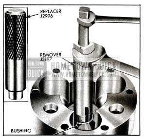
1955 Buick Replacing Planet Carrier Bushing
Reaming to size is not required.
- Inspect reverse band and replace it if cracked or lining is worn so that grooves are gone. Inspect reverse band anchor for cracks.
Cleaning and Inspection of 1955 Buick Dynaflow Transmission Case
- Wash case thoroughly and blow out all passages.
- Carefully inspect case for cracks, breaks, and stripped threads in bolt holes.
- Inspect all machined surfaces for nicks or burrs and smooth off with a mill file.
- Inspect the bushing for wear and scoring.
Insert planet carrier into bushing and check clearance with feeler gauge. If clearance is excessive due to wear of bushing, replace the bushing.
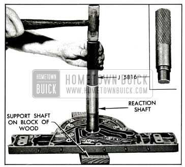
- To remove old bushing, place case over an opening with rear end down and drive bushing from case with Remover J 3175-1. To install new bushing place J 3175-2 in rear oil pump recess of case to serve as a pilot, slip bushing over J 3175-1 and drive bushing into case from front side until bushing is flush with front surface of wall which supports the bushing. Bushing must be installed with the wide deep ends of oil grooves toward rear side of case. See figure 5-82.
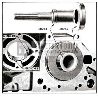
1955 Buick Transmisslon Case Bushing Remover and Replacer J 3175
Assembly of 1955 Buick Dynaflow Planetary Gear Set
- Re-assemble planet pinions and shafts with bearing rollers and thrust washers. The bottom thrust washer goes between retaining ring on shaft and the end of pinion. Each reverse planet pinion contains 24 rollers. Each low planet pinion contains 20 rollers at each end separated by a spacer. See figure 5-80. Place a thrust washer on upper end of each assembly to hold rollers in place.
- Make sure that steel ball is embedded in each shaft to prevent turning in carrier, then install planet pinion assemblies in front end of planet carrier, using care to engage the steel balls in the notches in carrier. See figure 5-79.
- Install reverse sun gear and place bronze thrust washer on top of gear.
- Install rear end of planet carrier on the assembled front end, making sure that the assembly marks on both parts are in alignment. These marks are numbers which are placed over the parting line during production of the carrier.
- Install the 3 screws with special lockwashers and tighten to 25-30 ft. lbs. torque with a 7/32″ hexagon (Allen) wrench.
- Install reverse ring gear on planetary gear set.
- See paragraph 5-23 (b) for installation of 1955 Buick Dynaflow planetary gear set.
5-23 ASSEMBLY OF 1955 BUICK DYNAFLOW TRANSMISSION FROM MAJOR PARTS AND UNITS
General Instructions
- Before starting to assemble the 1955 Buick Dynaflow transmission make certain that all parts are absolutely clean. Keep hands and tools clean to avoid getting dirt into assembly. If work is stopped before assembly is completed cover all openings with clean cloths.
- All moving parts should be given a light coating of 10-W oil before installation. Thrust washers may be held in place with vaseline or chassis lubricant, sparingly applied.
- Do not take a chance on used gaskets and seals-use new ones to avoid oil leaks.
- Use care to avoid making nicks or burrs on parts, particularly at bearing surfaces and surfaces where gaskets are used.
- It is extremely important to tighten all parts evenly and in proper sequence, to avoid distortion of parts and leakage at gaskets and other joints. Use a reliable torque wrench to tighten all bolts and nuts to specified torque and in the specified sequence.
- Prepare two 5/16″x2 1/2″ guide pins and two 3/8″x 1 3/8″ guide pins with screwdriver slot in plain end, as shown in figure 5-83. These will be used for alignment of parts during assembly.
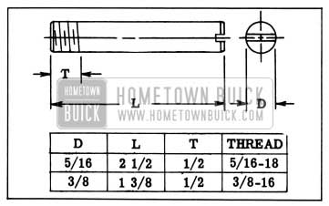
1955 Buick Guide Pins
Installation of 1955 Buick Dynaflow Planetary Gear Set
- Install reverse ring gear rear thrust washer in 1955 Buick Dynaflow transmission case.
- Compress ends of reverse band with Band Installing Clip J 2595 and install in case. See figure 5-84. Remove the clip. NOTE: Reverse band does not have strut locating pins in ends low band has pins.
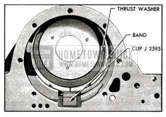
1955 Buick Ring Gear Thrust Washer and Reverse Band Installed
- Rotate the reverse band toward servo opening, insert anchor through opening and engage with hooked end of band, then rotate band and anchor back to normal position.
- Hold band operating lever (with offset end) in place with strut shoulder toward inside of case, and insert anchor shaft through case, anchor, and lever. Tapped end of shaft must be outward. If adjustment screw is not centered in servo opening, the low band operating lever has been installed by mistake. See figure 5-85.
1955 Buick lnstalling low Band Operating Lever and Shaft
- Install ring gear over planet carrier and place planet carrier bronze thrust washer on carrier with the three tangs engaged in holes in carrier. See figure 5-86.
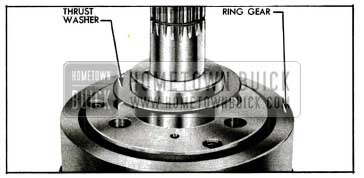
1955 Buick lnstallation of Front Thrust Washer
- Install assembled planetary gear set in 1955 Buick Dynaflow transmission case, using care to prevent thrust washer from dropping out of position.
Installation of Rear Oil Pump and Lubrication Oil Pressure Regulator Valve
- Place gasket and rear oil pump plate in recess in 1955 Buick Dynaflow transmission case and align the bolt holes, which are not equally spaced.
- Install oil pump drive key cushion (rubber) and drive key in output shaft, then install driving gear to engage the key. Install old gear in same position as before removal-install a new gear either way. See figure 5-87.
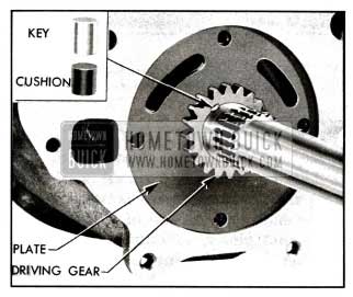
1955 Buick Oil Pump Driving Gear and Key Installed
- Lubricate both pump gears and pump body, then install driven gear and body over the driving gear and align bolt holes.
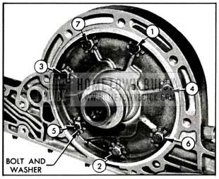
- Install pump bolts with lockwashers, tighten evenly to 5 ft. lbs. torque in sequence shown in figure 5-88 (A), then tighten in same sequence to 25-30 ft. lbs. torque.
1955 Buick Pump Bolt Tightening Sequence-lnstallation of Ratchet Wheel
- Turn output shaft to make sure pump operates freely.
- Install the lubrication oil pressure regulator valve spring, valve and valve seat in 1955 Buick Dynaflow transmission case. Tighten valve seat with locally prepared drag link socket shown in figure 5-37.
Installation of 1955 Buick Dynaflow Parking Lock Ratchet Wheel and Rear Bearing Retainer
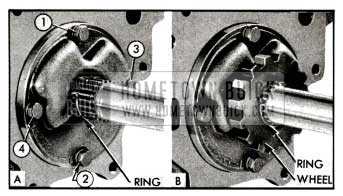
- Install a retaining ring in the forward groove in output shaft, install ratchet wheel, then install retaining ring in rearward groove in output shaft. See figure 5-88.
- Carefully examine splined end of output shaft, particularly adjacent to the groove for universal joint retaining ring. Remove burrs with a mill file to prevent damage to bushing in rear bearing retainer when this part is installed.
- Install rear bearing retainer and gasket on transmission case. Use lock washers on attaching bolts and tighten bolts evenly to 35-40 ft. lbs. torque.
- Install universal joint retaining ring in the groove in output shaft.
Installation of 1955 Buick Dynaflow Low band, Clutch, and Input Shaft
- Install the low band operating lever and shaft. Strut shoulder of lever must be toward inside of case and tapped end of shaft must be outward. See figure 5-89.
1955 Buick lnstalling low Band Operating Lever and Shaft
- With the assembly standing on end of rear bearing retainer, install a wooden block (1″x2″x3 1/2″) as shown in figure 5-89. Set both low band struts in position on block, with plain ends engaging strut shoulder of operating lever and groove in anchor shaft and with notched ends together and about 3/16″ from wall of case. Spread struts as far apart as possible.
- Compress ends of low band with Band Installing Clip J 2595 (fig. 5-90).
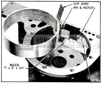
1955 Buick lnstallation of Low Band and Struts
NOTE: A used band must be reinstalled in original position heaviest wear will be at anchor end. A new band can be installed either way.
- Install band in case with ends between the struts and resting on the wooden block. Apply the operating lever to hold struts and band, remove clips and block, then press band down until the locating pins engage the notches in both struts.
- Reaction gear thrust washers of four different thicknesses are furnished under Group 4.161. Select the one that measures between .114″ and .117″, and install it over the reverse sun gear with groove toward sun gear. See figure 5-91.
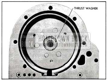
1955 Buick Reaction Gear Thrust Washer in Place
- Install 1955 Buick Dynaflow clutch assembly. If drum binds against low band so that clutch does not go all the way down, use a hooked wire to lift the band on side opposite struts.
- Place bronze thrust washer on front face of clutch hub, then use a flashlight to make sure that all four thrust washers are centrally located so that input shaft can be inserted.
- Make sure that ends of input shaft oil seal ring are properly locked, then install input shaft. It may be necessary to wiggle the shaft to get it through all four thrust washers.
Installation of 1955 Buick Dynaflow Reaction Shaft Flange, Front Oil Pump, and Accumulators
- Install a 5/16″ guide pin (fig. 5-83) in accumulator bolt hole at each end of flange on transmission case. See figure 5-92.
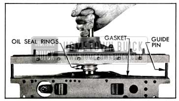
1955 Buick lnstalling Reaction Shaft Flange and Gasket
- Place reaction shaft flange gasket in position on case so that all holes in gasket and case are aligned. Gasket can be incorrectly installed.
- Make certain that oil seal rings are on flange hub, then install flange assembly on case using care to avoid damaging oil seal rings. See figure 5-92.
- Install 3 special bolts (3/8″-16×2″) with plain washers in positions marked 2, 3, 4 in figure 5-94.
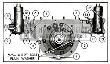
1955 Buick Reaction Shaft Flange and Accumulator Bolt Tightening Sequence
These bolts are for assembly purpose only. Install regular pump cover bolts, nuts, and lockwashers at positions marked 1, 5, 6. Coat threads of bolt No.5 with Permatex No.3.
- Tighten bolts marked 1 through 4 to 35-40 ft. lbs. and bolt 5 to 20-25 ft. lbs. in numerical sequence.
- Thread End Play Gauge J 5804 into rear end of the output shaft and thread Extension Rod J 5808 into a bolt hole in rear bearing retainer. Tighten both tools firmly.
- Use Clamp KM0-30-G and Sleeve KM0-30-K to mount Dial Indicator KM0-30-B and Extension J 5339 so that the extension bears squarely against the end of Gauge J 5804. See figure 5-93.
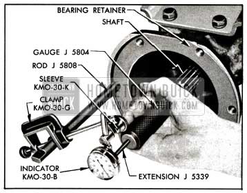
1955 Buick Checking Output Shaft End Play
- Push Gauge J 5804 as far forward as possible, set dial indicator at zero, then pull gauge rearward toward indicator with sufficient force to remove all end play from input shaft. Note indicator reading, which will be between .020″ and .034″ if output shaft end play is within proper limits.
- If end play is not within the specified limits, remove reaction shaft flange, clutch assembly, and the thrust washer located between the reaction gear and the reverse sun gear. See figure 5-91.
- Measure the thickness of removed thrust washer and substitute another one of proper thickness to bring output shaft end play within specified limits. If end play was less than .020″ select a thinner thrust washer; if end play was more than .034″ select a thicker thrust washer. Reinstall parts and check for specified end play.
- Place accumulator gaskets in position so that holes match the holes in reaction shaft flange. Install low accumulator on same side as low band operating lever and install high accumulator on opposite side of flange, first making sure that check ball and retaining pin are in place in high accumulator body.
- Coat accumulator bolt threads with Permatex No. 3 (non-hardening) and install bolts and stud nuts with lockwasher, but do not tighten.
- Referring to figure 5-94, tighten all bolts and nuts (1 through 14) to 5 ft. lbs. torque in the numerical sequence shown. Following the same sequence again, tighten bolts 1 through 4 to 35-40 ft. lbs. and the remaining bolts and nuts to 20-25 ft. lbs.
- Remove the three special bolts (2, 3, 4) and tighten accumulator body caps to 40-50 ft. lbs. torque.
- If edge of flange gaskets projects beyond bottom surface of 1955 Buick Dynaflow transmission case, carefully trim it flush, using a sharp knife.
Installation of 1955 Buick Dynaflow Valve and Servo Body Assembly, and Oil Pan
- With 1955 Buick Dynaflow transmission laying bottom side up, raise the reverse band operating lever and insert the strut between shoulders on lever and end of band-rounded ends must be against lever and band. CAUTION: Do not lift the lever during the following steps because strut will fall into transmission case.
- Install two 5/16″ guide pins (fig. 5-83) in transmission case to guide each end of servo body, and install servo body spacer plate gasket over guide pins.
- Push shift control valve and lower operating lever inward to align the upper lever with opening in case and install the valve and servo body on transmission case. See figure 5-95. Engage pin in control valve with slot in operating lever.
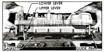
1955 Buick lnstalling Valve and Servo Body Assembly
- Install various length bolts with lockwashers according to depth of holes through valve and servo bodies. Use copper washer on center bolt adjacent to suction pipe opening. See figure 5-96.
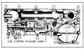
1955 Buick Valve and Servo Body Bolt Tightening Sequence
- Tighten all bolts to 5 ft. lbs. torque in the numerical sequence shown in figure 5-96. Repeating the same sequence, tighten all 1/4″ bolts and nuts to 11-15 ft. lbs. torque and all 5/16″ bolts to 15-20 ft. lbs. While tightening bolts and nuts adjacent to the shift control valve, operate the valve to make certain that it is not binding-it may be necessary to adjust some bolts to low limit on torque to prevent valve binding.
- Remove bolt No. 18 and nut No. 9 and install cork gasket, suction pipe, retaining spring and support as shown in figure 5-97. Tighten bolt and nut to 11-15 ft. lbs. torque.
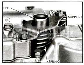
1955 Buick Oil Screen Suction Pipe Installation
- Using Linkage Hook-Up Finger J 2591, position the socket of valve operating rod under the ball of valve upper operating lever and pull upward until ball snaps into the socket. See figure 5-98.
1955 Buick Connecting Valve Operating Rod to Upper Lever
- Temporarily install the shift lever on cross shaft and operate the valve linkage to make sure it works freely. Move lever toward front of 1955 Buick Dynaflow transmission to engage parking lock pawl in the ratchet wheel. Turn output shaft to make certain it is locked.
- Push the shift control valve away from the stop pin just enough to remove play from valve linkage, then check clearance between stop pin and end of valve, using feeler gauge. Clearance should be .030″ to .040″. See figure 5-99.
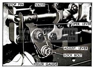
1955 Buick Control Valve Linkage Adjustments
- If clearance is not correct, loosen lock bolt and shift the adjusting lever on the valve lower operating lever as required to obtain specified clearance. Tighten bolt and nut on levers, making sure that adjustment does not change. See figure 5-99.
- Move shift lever two detent notches to Direct Drive position and note position of control valve. The inner end of valve should be within 1/32″ (either way) of the edge of hole in valve body indicated in figure 5-100.
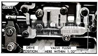
1955 Buick Position of Control Valve In Direct Drive Range
- If valve is not properly positioned in valve body, slightly loosen bolts attaching valve body to servo body and shift as required. Bolt holes permit some movement of valve body. Tighten bolts as specified in Step 5.
- Spread a thin coat of Permatex No.3 on transmission case only in the area where the case is cut away under the oil pan gasket. This is adjacent to the valve operating lever.
- Install a 5/16″ guide pin (fig. 5-83) at each end of transmission case and install a new oil pan gasket over guide pins. Install oil screen on suction pipe.
- Install oil pan with bolts and stud nuts provided with lockwashers. Evenly tighten all bolts and nuts to 15-18 ft. lbs. torque.
Installation of 1955 Buick Dynaflow Universal Joint, Torque Ball, and Speedometer Driven Gear
- Engage the parking lock pawl in ratchet wheel.
- Make sure the universal joint retaining ring is fully seated in groove in output shaft, then install universal joint using Replacer J 855 to draw universal joint snug against retaining ring. See figure 4-33.
- Install 1955 Buick Dynaflow universal joint plain washer, lockwasher, and bolt using a 3/4″ socket and tighten bolt to 30-35 ft. lbs. torque. CAUTION: Make certain that oil passage in bolt is clear.
- Install speedometer driver gear and sleeve assembly in rear bearing retainer.
- Install and adjust torque ball to 15-25 pounds drag, then install torque ball boot as described in paragraph 4-12.
Installation of 1955 Buick Dynaflow Bell Housing and Torque Converter
- Install front oil pump seal ring around pump body against pump cover.
- Install bell housing, using lockwashers on bolts and stud. Sparingly coat threads of lower right side bolt with Permatex No.3 because the bolt hole opens into transmission case. Tighten bolts and stud nut evenly to 35-40 ft. lbs. torque.
- Support converter pump firmly on blocks and carefully place stator in proper position, with original selective spacers and the thrust washer between stator and pump hub. Do not use grease to hold spacers in place.
- Place sun gear on stator with tanged thrust washer up, then carefully lower twin turbine assembly into place, making certain that planet pinions mesh properly with sun gear.
- Install Converter Clearance Gauge J 5899 on converter pump flange, making sure that indicator post does not contact the turbine. Loosen wing screw, firmly press gauge plunger down against first turbine hub and tighten wing screw. See figure 5-101.
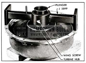
1955 Buick Gauge J 5899 on Pump and Turbine
- Support the 1955 Buick Dynaflow converter pump cover firmly on blocks with inner side up and place the bronze thrust washer in its recess. Remove Gauge J 5899 from pump, invert it, and center it on the cover so that it rests squarely on the gasket surface. See figure 5-102.
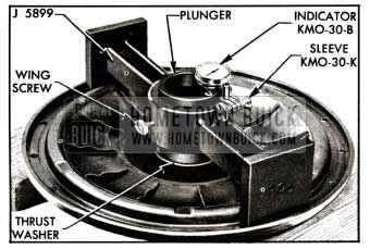
1955 Buick Gauge J 5899 on Pump Cover
- Use Sleeve KM0-30-K to mount Dial Indicator KM0-30-B on the adjustable post of clearance gauge so that indicator button bears squarely against the upper end of clearance gauge plunger. Set dial at zero. See figure 5-102.
- Loosen plunger wing screw, firmly press gauge plunger down against the thrust washer and note the dial reading. The dial reading is the clearance that will exist between the turbine and pump cover when parts are installed, and should be .018″ to .029″.
- If dial reading is not within specified limits, change the total thickness of selective spacers located under the stator. Increasing the spacer thickness will decrease clearance at cover and decreasing spacer thickness will increase the clearance. Spacers are available in three different thicknesses under Group 4.117.
- Install the converter pump on reaction shaft, turning it until lugs on pump hub enter the slots in front oil pump driving gear.
- Coat the selective spacers and thrust washer with petroleum jelly so that they will adhere to the stator during installation. Make sure that all rollers and springs are in place and held in stator with Tool J 5806 (fig. 5-43).
- While holding thrust washer and spacers to rear side of stator, slide stator off of installing tool upon the reaction shaft. Make certain that washer and spacers remain in place as stator is pushed back against converter pump.
- Install converter sun gear with the tanged thrust washer outward. If the sprag is properly installed, the sun gear may be turned on reaction shaft in clockwise direction only.
- Make sure that retaining ring is seated in groove of input shaft, then install the twin turbine assembly, turning it as required to mesh the planet pinions with the sun gear.
- Install selective thrust washer, retaining washer, and bolt with external tooth lockwasher on front end of input shaft. See figure 5-103.
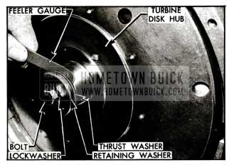
1955 Buick Checking Turbine Clearance
Shift into “Parking” and pry up on reverse band operating lever with screwdriver to lock input shaft, then tighten bolt to 30-35 ft. lbs. torque.
- Check clearance between selective thrust washer and first turbine hub, using feeler gauges. Clearance should be between .002″ and .009″. See figure 5-103.
- If specified clearance does not exist, substitute another thrust washer of proper thickness. Two washers of different thicknesses are available under Group 4.127.
- Looking at front face of converter pump cover, select the three bolt holes (X) that are aligned with the center of the hub and one of the counterbored recesses adjacent to hub. Mark these holes for later installation of the flywheel-to-pump driving bolts. See figure 5-104.
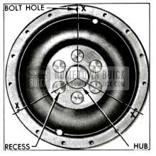
1955 Buick Location of Driving Bolt Holes
- Install a new O-ring seal on pump cover, making sure that surfaces are clean and that seal has even tension all around and is not twisted.
- Grease the selected thrust washer so it will adhere and place it in recess in cover, then install cover on pump so that the three marked driving bolt holes are not aligned with any hole in pump rim at which a balance weight is located.
- Install bolts with plain washers and special nuts in all but the three driving bolt holes, insert the shank of a 11/32″ drill through one bolt hole to align all holes, then tighten bolts to approximately 5 ft. lbs. torque in numerical sequence shown in figure 5-105. Finally tighten bolts in same sequence to 25-30 ft. lbs. torque.
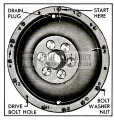
1955 Buick Bolt Tightening Sequence
When tightening bolts, insert a wide screwdriver blade between flat side of bolt head and the pump to prevent a corner of bolt from digging into pump casting.
Low and Reverse Band Adjustment
NOTE: The following adjustment must be very carefully performed since it is not possible to readjust the bands after transmission is installed in car.
- Loosen lock nut and turn adjusting screw clockwise until considerable resistance is felt, indicating that band is in full contact with the drum (low) or ring gear (reverse). See figure 5-106.
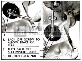
1955 Buick Band Adjustment
- Back off screw until just a trace of play can be felt by prying up on lock nut with screwdriver. From that point, back off screw six (6) complete turns and snug up the lock nut. See figure 5-106.
- After noting position of adjusting screw slot, tighten lock nut to 20-25 ft. lbs. torque. Remove torque wrench and check to make sure that adjusting screw did not turn.
- Install band adjustment covers with new gaskets. Tap covers firmly into opening in rear bearing retainer.
- Install 1955 Buick Dynaflow transmission shift lever on cross shaft with lockwasher and nut, hold lever forward while tightening nut, to avoid straining the internal linkage.
Leave A Comment
You must be logged in to post a comment.