SECTION 11 -B 1955 BUICK HEATER, AIR CONDITIONER
11-6 1955 BUICK HEATER AND DEFROSTER
1955 Buick Heater Installation
The 1955 Buick heater is mounted in the floor of body under the left side of front seat. In contains an electric blower which draws air from the body through the hot water core and recirculates the heated air at floor level. The hot water is supplied directly from the engine water manifold and the volume of hot water is controlled by the temperature control valve described in subparagraph e.
1955 Buick Defroster and Outside Air Ventilation
The 1955 Buick defroster operates in conjunction with the outside air ventilation system which is standard equipment on all models. The ventilation system operates as follows.
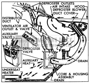
The air stream flowing over the hood during forward motion of the car enters an air intake duct built into the cowl along the base of the windshield. Two ventilator air duct covers mounted on left and right sides of the dash panel under the hood, redirect the air stream directly into the passenger compartment through air outlets in the dash panel. The volume of air entering the passenger compartment is controlled by fly valves which are connected by bowden wires to control knobs on the instrument panel. Water separated from the air as the air stream reverses direction in the S-shaped passages is caught by a trough and drained through a hose at the bottom of each air duct cover. See figure 11-12.
1955 Buick Heater, Defroster, and Ventilator Installation
The 1955 Buick defroster blower mounted on the right hand air duct cover is connected by a flexible tube to the defroster core and housing assembly mounted on the right side of cowl behind the cowl trim pad. The 1955 Buick defroster inner housing is connected by a flexible tubing to a distributor duct and four outlets mounted along the base of the windshield. See figure 11-12.
When the 1955 Buick defroster blower is turned on, outside air is forced through the defroster core where it is heated by hot water from the engine and is then forced upward against the windshield which deflects the flow rearward into the body at shoulder level. The volume of air passing through the defroster core is controlled by a fly valve in the 1955 Buick defroster inner housing which is connected by a bowden wire to the middle control knob on instrument panel.
The 1955 Buick defroster inner housing contains an auxiliary valve which may be opened to provide heating from the defroster core at floor level. This valve is connected by a bowden wire to the right hand control knob on instrument panel. See figure 11-12.
Water Flow and Temperature Control Valve
The hot water supply for the 1955 Buick heater and defroster cores is taken from the outlet side of the 1955 Buick engine water manifold, from which it is conducted by hoses to the underseat heater, then to the temperature control valve mounted on the dash panel, to the defroster core and finally to the bottom of radiator core.
The volume of hot water flowing through the 1955 Buick heater and defroster cores is regulated by the thermostatically actuated temperature control valve. When the car is cold the temperature control valve stands open to permit maximum flow of water through the 1955 Buick heater and defroster cores. As the body air temperature comes up to the level for which the temperature control is set the valve operates to reduce the water flow and maintain the desired air temperature.
1955 Buick Heater, Defroster, and Ventilator Operation Controls
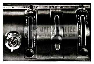
The temperature control valve is manually set to the desired body air temperature by moving the left hand control knob upward into the “WINTER RANGE.” See figure 11-13.
1955 Buick Heater, Defroster, Ventilator Controls
Once set for a desired body temperature the temperature control unit will automatically maintain this temperature without further adjustment of the control lever. Since the air-temperature will come up to the level as rapidly as existing water temperature will permit it is unnecessary and undesirable to attempt quick warm-up by manipulating the temperature control lever.
Hot water flow through the 1955 Buick heater and defroster cores is completely shut off when the temperature control lever is in the “OFF” position. This shuts off all heat when not desired, such as for summer driving. This feature eliminates the need for a shut-off valve in water line at engine.
The 1955 Buick heater blower is controlled by the 3-position toggle switch mounted above the left hand control knob. The blower may be set for “HI” speed or “LOW” speed by setting the switch to right or left position as indicated on instrument panel. See figure 11-13.
The single speed 1955 Buick defroster blower is controlled by the toggle switch mounted above the right hand control knob on 1955 Buick instrument panel. The 1955 Buick defroster valve in defroster housing is opened by moving the middle control knob upward. The auxiliary valve in defroster housing is opened by moving the right hand control knob upward. Both valves may be partially but not fully opened at the same time. As one valve is moved to the wide open position, it would contact and completely close the other valve.
Right and left ventilator fly valves in air outlets are operated by the right and left control knobs, respectively. Either valve may be opened by moving its control knob into the “SUMMER” range.
NOTE: To keep out offensive traffic odors and exhaust gases when traveling in congested traffic or when parked behind a car having its engine running, all ventilator and defroster valves must be closed and the defroster blower must be turned off.
WARNING-CARBON MONOXIDE
Avoid inhaling exhaust gases when any concentration of these is present in the air, i.e., in a garage, in congested traffic, or when stopped closely behind a vehicle with its motor running. Exhaust gases may have strong odors which normally should give warning of their presence. However, the exhaust gases from some vehicles may not be noticeable under certain conditions and the senses of people react differently. Exhaust gases contain a percentage of carbon monoxide, which is a poisonous gas that, by itself, is tasteless, colorless, and odorless.
Temperature Control Valve Wire Adjustment
The 1955 Buick temperature control valve is operated by a lever through a sheathed operating wire. To insure full range of temperature control, the valve must act as the stop at both ends of lever travel. Since the operating wire is of fixed length with loops at each end, full range of operation is obtained by clamping the operating wire sheath in proper location on the control lever support and the temperature control assembly as follows:
- Connect operating wire to control lever and clamp end of sheath 1/8″ from edge of clamp on lever support.
- Turn temperature control valve all the way clockwise until the cam locks against the roller. This is the extreme “off” position. Connect operating wire to brass post on valve and clamp the sheath to valve assembly.
- Operate the control lever through full range to make certain that the valve provides the stop at both ends.
11-7 1955 BUICK AIR CONDITIONER
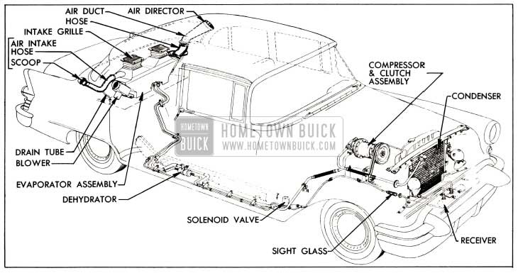
Locations of the various units of the 1955 Buick Air Conditioner system and their connecting pipes are shown in figure 11-14.
1955 Buick Air Conditioner Installation
Figure 10-80 shows the electrical control circuits, which are entirely separate from all other chassis and body wiring circuits.
Except for the axial type compressor which replaces the rotary type, the 1955 Buick Air Conditioner installation is essentially the same as in 1954 models. The service information contained in the 1953-1954 Buick Air Conditioner Shop Manual (B.P.S. 7.26) is generally applicable to the 1955 Buick installation except for the compressor service operations given in paragraph 11-8, below.
Any service work that requires breaking a pipe joint should be performed only by mechanics who have been trained in Buick or other automotive air conditioning schools. Whenever a pipe is disconnected from any unit except the compressor, liquid or vaporized refrigerant will escape unless the proper procedure is used. Any work involving the handling of refrigerant requires special equipment and a knowledge of its proper use.
Operating Instructions
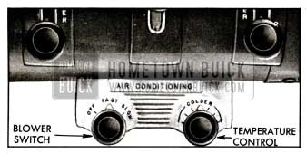
Operation of the 1955 Buick Air Conditioner is controlled by two switch knobs located on instrument panel. See figure 11-15.
1955 Buick Air Conditioner Control Panel
To start 1955 Buick Air Conditioner operation, turn the left hand switch knob to “FAST” or “SLOW” as required by car temperature. For maintaining comfort after car is cooled down, the “SLOW” fan speed should be used except in the most extreme summer heat.
The temperature level of the air supply may be set at any point between 67° and 80° F. to suit the personal comfort of car occupants. This is done by turning the right hand knob (fig. 11-15). The first movement of the knob from the extreme counterclockwise position turns on the temperature control circuits and energizes the compressor clutch solenoid, placing compressor in operation. After a click is heard, further movement clockwise operates the rheostat to vary the temperature setting.
It is not necessary to set the temperature control to coldest position in order to cool out the car. When the knob is set for the desired temperature level, the Air Conditioner will soon bring the interior temperature to that level and will maintain it until the knob is given a different setting.
If car has been standing in the sun it may be aired out by opening doors and windows. When the Air Conditioner is stared, however, all windows and ventilators must be closed in order that all outside air entering the passenger compartment will be admitted only through the Air Conditioner.
Distribution of cooling air is controlled by an air director on the upper end of each transparent 1955 Buick air duct above the parcel shelf. The air director may be rotated to direct cooling air in any desired direction.
11-8 COMPRESSOR SERVICE PROCEDURES
NOTE : Before the engine is raised or lowered for any service operation the high and low pressure valves with lines attached must be disconnected from 1955 Buick air conditioning compressor, as described in subparagraph a, steps 1 through 6.
Removing and Installing of 1955 Buick Air Conditioner Compressor
- Remove protective caps from gauge fittings of high and low pressure valves on rear end of compressor.
- Connect charging lines of Pressure Gauge Set (fig. 11-16) to gauge fittings of both valves, with both valves of Manifold J 5415 closed.
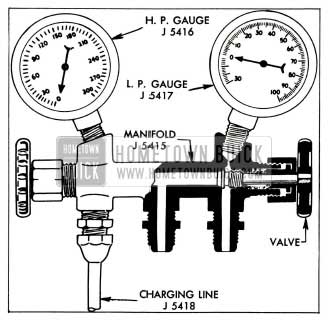
1955 Buick Pressure Gauge Set
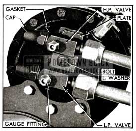
1955 Buick High and Low Pressure Valve Installation
Do not place compressor in sun or near heat because it still contains some Freon-12.
- Install compressor by reversing procedure for removal, paying attention to the following points.
- Inspect drive belts and pulley grooves for conditions that might cause slippage. If a belt is cracked, frayed, or oil soaked, or is worn so that it bottoms in pulley grooves replace both belts. Belts are furnished in matched sets only, to insure even tension.
- Adjust drive belts to 1/2″ deflection midway between fan and compressor pulleys. See figure 10-10.
- Use new O-rings when attaching valve assembly to compressor.
- Before starting compressor make sure that both valves are fully opened.
- After operating compressor for ten minutes at 1750 RPM, leak test around the valve mounting plate.
Replacement of 1955 Buick Clutch Parts
NOTE: If compressor is mounted on engine, first remove drive belts and disconnect clutch solenoid wire.
- Remove clip ring and dust cap from pulley hub, then remove bolt, lockwasher and retainer. See figure 11-18.
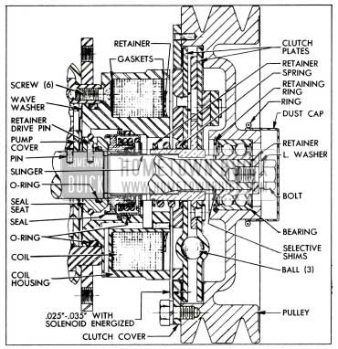
1955 Buick Clutch and Shaft Seal-Sectional View
NOTE: If pulley hub shows wear caused by rotation of outer race of bearing, replace the pulley.
- Inspect frictional surfaces of clutch plates for dirt, scoring or other damage. If necessary to replace either plate, disassemble by removing the spring retainer ring, using Ring Pliers J 4880.
- Inspect solenoid coil for damaged insulation, frayed or broken leads, or loose terminals. Repair or replace as necessary.
- Install inner (notched) insulator gasket, coil, and outer gasket in coil housing, then install a new coil retainer with teeth pointing outward. Tap each tooth to insure that coil is held firmly in place.
- Place clutch cover over coil housing with ground surface facing outward, then install clutch plate assembly with spring extending into coil housing. One spline on shaft is cut low to locate clutch plates for proper balance.
- Install the original selective shims against the shoulder on shaft, then install pulley. Apply pressure only against inner race when pressing bearing over end of shaft and into firm contact with the shims.
- Install retainer and bolt with lock washer; tighten bolt securely.
- Attach clutch cover to pulley with bolts and lockwashers.
- Connect solenoid coil leads to 12 volt battery to energize coil, then check clearance between rear clutch plate armature and coil housing, using brass or bronze feeler gauges. This clearance should be .025″-.035″. See figure 11-18.
- If clearance is not within specified limits remove pulley and change thickness of the selective shims as required. Shims are available in thicknesses of .015″, .020″ and .025″. When clearance is correct install dust cap and clip ring on pulley hub.
Replacement of 1955 Buick Shaft Seal
- Remove pulley, clutch plates and solenoid coil (subpar. b, above).
- Remove six Phillips head screws, then carefully pry the coil housing away from compressor body. An oil slinger pressed on the shaft will come out as housing with seal is removed. See figure 11-18.
- Press old seal assembly out toward shouldered end of housing, remove O-ring from external and internal grooves then thoroughly clean the seal seat and O-ring grooves.
- Use small screwdriver to force the drive pin retainer out of groove to rest on inner end of seal seat on compressor shaft. Be careful not to mar the oil pump cover.
- Remove drive pin, using needle nose pliers, then remove seal seat from shaft.
- Wipe shaft clean with tissue from seal package. Check shaft spline for burrs or sharp edges, which must be removed with a hard Arkansas stone. Clean shaft again to remove any stone or metal dust.
- Install new O-ring inside the new seal seat and place seat with beveled end down on a piece of oil soaked tissue to protect the polished seating surface. NOTE: Use every precaution to prevent damaging this surface and do not touch it with fingers at any time.
- Place old seat over new one and force the drive pin retainer down over new seat, working it down to area between the groove and beveled end.
- Coat O-ring with clean Frigidaire oil and install seat on compressor shaft with drive pin holes aligned, being careful not to damage O-ring on shaft splines.
- Install drive pin and force the retainer into groove over the pin.
- Examine the oil pump cover plate to make certain the small dowel pin is in proper place and flush with outer cover. Also make certain that wave washer is in place.
- Install new internal and external O-rings in grooves of coil housing and coat adjacent areas with clean Frigidaire oil.
- Press new seal assembly squarely into place in coil housing with spring loaded disk toward shouldered rear end of housing. Apply pressure only against the outer flange of seal casing until flange bears against shoulder in housing.
- Install housing on compressor with notch for coil leads in line with pressure relief valve on rear end of compressor. Install six screws and tighten securely.
- Press oil slinger over shaft to allow running clearance with seal casing.
- Install solenoid coil, clutch plates and pulley (subpar. b, above).
Leave A Comment
You must be logged in to post a comment.