SECTION 2-D 1955 BUICK CYLINDER HEAD AND VALVE MECHANISM SERVICE
2-14 1955 BUICK CYLINDER HEAD AND VALVE SERVICE
Removal of 1955 Buick Cylinder Head
- Drain the 1955 Buick radiator and cylinder block.
- Remove air cleaner and silencer, then disconnect all pipes from carburetor and intake manifold.
- Disconnect wires from accelerator vacuum switch, remove coil, remove throttle return spring, disconnect equalizer shaft bracket from engine.
- Remove intake manifold and carburetor as an assembly. Remove manifold gaskets.
- When removing RIGHT cylinder head; (1) remove oil gauge rod, (2) disconnect Dynaflow filler pipe bracket from head, (3) remove generator mounting bracket, (4) remove air conditioning compressor, if present.
When removing LEFT cylinder head; (1) disconnect temperature gauge tube, (2) remove power steering gear pump with mounting bracket, if present, and move it out of the way with hoses attached.
- Remove spark plug cover and disconnect wires from spark plugs.
- Disconnect water manifold from both 1955 Buick cylinder heads and disconnect exhaust manifold from head to be removed.
- With air hose and cloths, clean dirt off cylinder head and adjacent area to avoid getting dirt into engine. It is extremely important to avoid getting dirt into the hydraulic valve lifters.
- Remove rocker arm cover and remove rocker arm and shaft assembly from cylinder head. Lift out push rods.
- Slightly loosen all 1955 Buick cylinder head bolts then remove bolts and lift off the cylinder head. Remove gasket.
- With cylinder head on bench, remove all spark plugs for cleaning and to avoid damage during work on the head.
Reconditioning Valves and Guides
Place 1955 Buick cylinder head on Holding Fixture J 5251 with valve springs straight up. Compress valve springs with fixture lever and remove the spring cap keys, then remove the springs and caps. See figure 2-15.
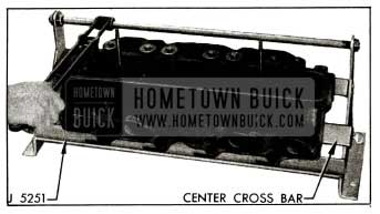
1955 Buick Removing Valve in Holding Fixtures J 5251
- Carefully roll 1955 Buick cylinder head away from holding fixture until one edge rests on bench, then remove valves. Place valves in a stick with numbered holes to keep them in order for reinstallation in original positions.
- Scrape all carbon from combustion chambers, piston heads, and valves. Clean all carbon and gum deposits from valve guide bores. When using scrapers or wire brushes for removing carbon, avoid scratching valve seats and valve faces.
- Inspect valve faces and seats for pits, burned spots or other evidences of poor seating. If a valve head must be ground until the outer edge is sharp in order to true up the face, discard the valve because the sharp edge will run too hot.
- Check fit of valve stems in guides. If clearance is excessive replace the guides, as follows:
- Remove center cross bar from Holding Fixture J 5251, place 1955 Buick cylinder head in fixture so that inlet port side rests against the fixture lower bar, then drive guides out from combustion chamber side using Driver J 269. See figure 2-16.
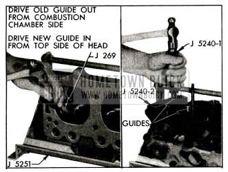
1955 Buick Removing and Installing Valve Guide
Replacement of 1955 Buick Rocker Arms
- Remove cotter pin, flat washer and spring washer from each end of the rocker arm shaft and remove bolts from brackets. Remove rocker arms, brackets and springs from shaft.
- Clean and inspect all parts and replace those that are excessively worn.
- Assemble springs, rocker arms and brackets on shaft as shown in figure 2-17.
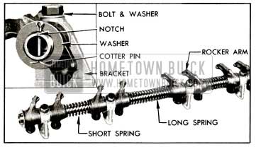
1955 Buick Rocker Arm and Shaft Assembly
Note that the long spring is at middle of shaft, the valve ends of all rocker arms slant toward middle of shaft, and a bracket is located between each pair of rocker arms.
Installation of 1955 Buick Cylinder Head
Make certain that gasket surfaces and all parts are absolutely clean, then install 1955 Buick cylinder head by reversing the procedure for removal, paying particular attention to the following points.
- When handling the thin crimped steel gasket use care to prevent damage to the lacquered surface coat and to prevent kinking at sealing rings stamped in gasket. The lacquered gasket should not be coated with any type of sealing material when installed. Always use a new steel gasket because the stamped sealing rings are flattened in a used gasket.
- Right and left cylinder heads are identical except that the water inlet port is open at front end and is plugged at rear end as installed on engine.
- After installation of cylinder head, tighten all bolts a little at a time about three times around in sequence shown in figure 2-18, then finally tighten in same sequence to 63-73 ft. lbs. torque.
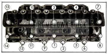
1955 Buick Cylinder Head Bolt Tightening Sequence
Always use an accurate torque wrench when tightening cylinder head bolts, to insure uniform and proper torque on all bolts. Uneven or excessively tightened bolts may distort cylinder bores, causing compression loss and excessive oil consumption.
- Install locking plates with exhaust manifold bolts, tighten bolts only to 10-15 ft. lbs. torque, then bend one tab of plate against a flat on each bolt head.
- When rocker arm and shaft assembly is installed, make certain that the notch in one end of shaft is upward in line with bracket bolt heads. See figure 2-17.
- After installation is completed and engine has been warmed up to operating temperature, recheck cylinder head bolts for 63-73 ft. lbs. torque.
2-15 1955 BUICK HYDRAULIC VALVE LIFTER SERVICE
Removal of 1955 Buick Valve Lifters
- Remove 1955 Buick air cleaner and silencer, then disconnect all pipes from carburetor and intake manifold.
- Disconnect wires from the accelerator vacuum switch and remove the throttle return spring. Remove resistance unit, ignition coil, and equalizer shaft bracket from intake manifold and move these parts out of the way.
- Remove intake manifold and carburetor as an assembly. Remove manifold gaskets.
- With air hose and cloths, clean dirt from 1955 Buick cylinder heads, valve lifter cover and adjacent area to avoid getting dirt into engine. It is extremely important to avoid getting dirt into the hydraulic valve lifters.
- Remove rocker arm cover, rocker arm and shaft assembly, and push rods from bank where valve lifters are to be removed.
- Remove valve lifter cover and remove the valve lifters that require service. Place lifters in a wooden block having numbered holes or use other suitable method of identifying them according to original position in engine.
If less than a full set of lifters is being removed, immediately disassemble and inspect one or two for presence of dirt or varnish (subpar. c). If lifters contain dirt or varnish it is advisable to remove all lifters for cleaning and inspection; otherwise it will be satisfactory to service only those lifters that are not operating properly.
- Examine the cam contact surface at lower end of each lifter body. If this surface is excessively worn, galled, or otherwise damaged discard the lifter assembly. In this case also examine the mating camshaft lobe for excessive wear or damage.
Cleaning Tank J 5093 and Cleaning Fluids
Cleaning Tank J 5093 is designed to permit a systematic and thorough cleaning of hydraulic valve lifter parts. It provides three compartments for cleaning fluids, two 16-compartment cleaning trays, one small tray for special tools and a removable cover. The two cleaning trays allow one set of lifters to be soaking while another set is being worked on. The cover, placed on bench in front of tank, provides an easily cleaned working surface. See figure 2-19.
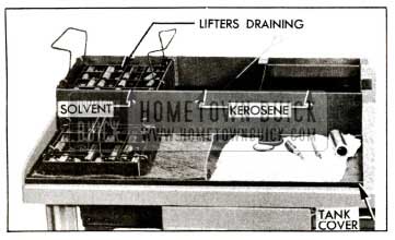
1955 Buick Tank J 5093 Set Up for Cleaning Lifter Parts
The left hand compartment of tank is for cleaning solvent in which parts are soaked after disassembly. The solvent required should either dissolve the varnish deposit on lifter parts or soften the varnish so that it can be removed by wiping, after soaking for not longer than one hour. Gulf Motor Flush, or an equivalent solvent, will effectively clean lifter parts.
When selecting a cleaning solvent, careful consideration should be given to its effect upon the hands. The directions and safety precautions of the manufacturer should be understood and observed to avoid personal injury. A wise safety rule is to wear rubber gloves when handling parts that are wet with cleaning solvent.
The middle compartment of tank is for clean kerosene to be used for cleaning parts after removal from the cleaning solvent. The right hand compartment is for clean kerosene to be used exclusively for final rinsing of parts just before assembly.
When the cleaning tank is not being used the cover should be installed to exclude dirt from the cleaning fluids. As a further precaution, do not use the tank for any parts except hydraulic valve lifters.
To avoid early contamination and deterioration of the cleaning solvent a separate pan of suitable size should be provided so that a tray of lifter parts can be flushed in kerosene before it is placed in the solvent.
Disassembly and Cleaning of 1955 Buick Lifters
- Disassemble each valve lifter by using a push rod to hold down the push rod seat while removing the plunger retainer from the lifter body, using Retainer Remover J 5238. See figure 2-20, View A. Remove push rod seat and plunger from lifter body.
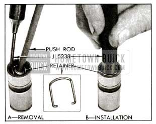
1955 Buick Removing and Installing Plunger Retainer
If a plunger sticks in lifter body place lifter in large end of Plunger Remover J 4160-A, with plunger inward. While holding lifter with thumb, rap the open end of remover against a block of wood with just enough force to jar the plunger from body. See figure 2-21.
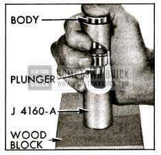
1955 Buick Removing Stuck Plunger with J 4160-A
- Drain oil out of body into a waste can and then remove the ball, retainer and spring. A strainer placed over waste can will prevent dropping these parts into can.
- Place all parts of each lifter in a separate compartment of a tray from Cleaning Tank J 5093. The body and plunger are selectively fitted to each other and must not be interchanged with parts of other lifters. Keeping all parts of the lifter together until cleaned and inspected will aid in diagnosing cause of improper operation.
- Rinse the tray full of lifter parts in a pan of kerosene to remove as much oil as possible. This will reduce contamination of the cleaning solvent and extend its effective life.
- Submerge the tray and parts in the cleaning solvent in left hand compartment of Cleaning Tank J 5093 and leave to soak for approximately one hour. The time required will depend on the varnish on lifter parts and the effectiveness of the solvent.
- After the varnish has dissolved or has softened sufficiently to permit removal by wiping, raise the tray and suspend it above the solvent by means of the hooks on tray handles. Allow tray and parts to drain so that solvent will be saved.
- Rinse the tray of parts in the pan of kerosene to cut the solvent and avoid injury to hands, then place tray on the tank cover located on bench in front of cleaning tank.
- Working on one lifter at a time and using CLEAN lint-free cloths, thoroughly wipe off all parts. Clean the plunger and the external and internal surfaces of the body with a hard wiping action to remove any varnish deposits. Rinse the parts in the kerosene contained in the middle compartment of cleaning tank, using Cleaning Brush J 5099 in the bore of lifter body.
NOTE: To insure absolute cleanliness of a reconditioned lifter assembly, it is advisable to inspect, check ball travel, and assemble each (lifter subpar. d, e, f) before cleaning the next lifter.
Inspection of 1955 Buick Hydraulic Lifter Parts
- Lifter Body. Inspect inner and outer surfaces of body for blow holes and scoring. Replace lifter assembly if body is roughly scored or grooved, or has a blow hole extending through the wall in position to permit oil leakage from lower chamber. The prominent wear pattern just above lower end of body should not be considered a defect unless it is definitely grooved or scored; it is caused by side thrust of cam against body while the lifter is moving vertically in its guide.
Inspect the cam contact surface on lower end of lifter body. Replace the lifter assembly if this surface is excessively worn, galled, or otherwise damaged. A lifter body that has been rotating will have a round wear pattern and a non-rotating lifter body will have a square wear pattern with a very slight depression near the center. Either condition is normal and such bodies may be continued in use if the surface is free of defects. See figure 2-22.
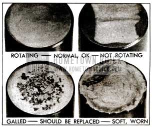
1955 Buick Lifter Body Wear Patterns
A blackened appearance is not a defective condition. Sometimes the discoloration serves to highlight slight grinder chatter marks and give the outer surface of plunger a ridged or fluted appearance. This condition will not cause improper operation, therefore it may be disregarded.
Check Ball Travel
It is very important to check the travel of the check ball and to bring it within prescribed limits before the lifter is assembled. Too much ball travel will allow excessive flow of oil from the lifter lower chamber just before the ball seats, causing excessive lash in the valve linkage. Insufficient ball travel will cause the volume of oil in the lower chamber to increase or “pump up,” thereby preventing the engine valve from seating.
- Prepare the ball travel checking attachment of Test Fixture J 5095 by using Sleeve KM0-30-K to mount Dial Indicator KM0-30-B so that stem of indicator bears squarely on upper end of the pin in attachment. See figure 2-23.
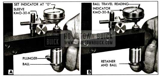
1955 Buick Checking Ball Travel
Assembly of 1955 Buick Hydraulic Lifters
All parts must be absolutely clean when a hydraulic lifter is assembled. Lint and dust may adhere to the parts if they are blown off or wiped with cloths; therefore they should be rinsed in CLEAN kerosene and assembled without drying.
- Rinse lifter plunger in the kerosene in middle compartment of cleaning tank and then give it a thorough final rinsing in the kerosene in right compartment.
- Hold plunger in vertical position with feed hole up, then rinse and install the check ball, ball retainer, spring, and body over the plunger. See parts in figure 2-24.
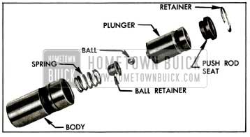
1955 Buick Hydraulic Valve Lifter Parts
Testing Lifter Leakdown Rate
After a hydraulic lifter has been cleaned, inspected, checked for ball travel, and assembled it must be tested before it is installed in an engine. Lifter Test Fixture J 5095 has been designed to test the leakdown rate of a lifter to determine whether it is within limits which assure satisfactory lifter operation.
The following procedure must be carefully followed to obtain an accurate test.
- Thoroughly clean the cup of test fixture, install cup on fixture, and fill it to within %” of the top with “Hydraulic Lifter Test Fluid,” which is available through Kent-Moore Organization, Inc., under K-M number J 5268.
- Remove rubber washer (used for larger lifters) and install Gauge Sleeve J 5180-5 in the cup; also install Buick V-8 Gauge Rod Nose J 5181-2 in the ram.
- Swing the weight arm up out of the way, raise the ram and place the valve lifter (top side up) in sleeve J 5180-5. The lifter must be completely covered by the fluid during test.
- Lower the ram to rest in the lifter push rod seat, then lower the weight arm to rest on the roller of ram as shown in figure 2-25.
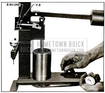
1955 Buick Checking Leakdown Rate
Finally, pump vigorously for approximately 10 additional strokes to make sure all air is removed from the lifter. NOTE: If one stroke offers noticeable weak resistance during the last 10 pumping strokes replace the check ball in lifter and repeat the leakdown test to this point.
- Raise weight arm to allow the lifter plunger to come up to its retainer, then lower the arm to rest on the ram roller. As the pointer starts moving upward start rotating the fluid cup by turning the handle one revolution every two seconds. See figure 2-25.
- Use a stop watch to check the time required for the pointer to move from the lower to the upper mark on scale where marked “BUICK V-8.” The cup must be rotated during this test. See figure 2-25.
- The leakdown rate (time between marks) must be between 12 and 40 seconds to assure satisfactory lifter performance. A doubtful lifter should be tested three or four times. Replace any lifter which does not test within the specified limits.
- After all lifters have been tested, place the cover over the test fixture to keep dirt out of the cup and fluid. The fluid should be discarded and the cup should be thoroughly cleaned after a few sets of lifters have been tested.
Installation of 1955 Buick Valve Lifters
Make certain that valve lifter guide holes and adjacent area of 1955 Buick cylinder block are clean, then oil and install valve lifters. Each lifter must slide freely in its guide hole; if a lifter is tight in one guide hole fit it to another hole.
Complete the installation of all parts by reversing the procedure for removal. An initial adjustment for clearance is not required, therefore, the valve train does not have any provision for adjustment after assembly.
2-16 1955 BUICK TIMING CHAIN, COVER, AND CAMSHAFT SERVICE
Remove and Install 1955 Buick Timing Chain
- Drain engine cooling system, then remove radiator core, shroud, fan belt, fan and pulley, and crankshaft balancer.
- Remove all bolts that attach the timing chain cover and the water manifold to the upper and lower crankcase and the 1955 Buick cylinder heads. Do not remove five small bolts attaching water pump to chain cover. Remove cover and manifold, using care to avoid damaging lower crankcase (oil pan) gasket.
- Remove oil slinger from crankshaft and remove the bolt, lockwasher and plain washer that attaches the fuel pump operating eccentric and the camshaft sprocket to front end of camshaft.
- If there has been doubt about the valve timing, turn crankshaft until the camshaft sprocket keyway is straight down toward the crankshaft and the “0” timing marks on both sprockets are toward left side of engine. If timing chain is installed to provide correct valve timing, there will be 12 teeth between the “0” timing marks, including teeth aligned with the marks. See figure 2-26.
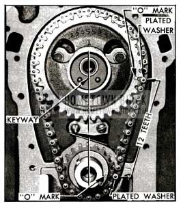
1955 Buick Timing Chain and Sprockets Properly Installed
Replacement of 1955 Buick Crankshaft Oil Seal in Timing Chain Cover
- With timing chain cover on bench, remove the braided fabric packing with a screwdriver and then tap the pressed steel shedder out of the cover.
- Work new packing into the shedder, then drive shedder into recess in timing chain cover, using Installer J 5250-1. See figure 2-27, view A.
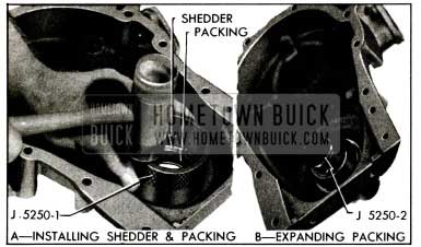
1955 Buick lnstalling Crankshaft Oil Seal
1955 Buick Camshaft Bearings and End Play
The five steel-backed babbitt-lined camshaft bearings are pressed into the crankcase. Going from front to rear, each bearing is bored .030″ smaller than the preceding bearing, and each camshaft journal is correspondingly reduced in diameter.
The camshaft bearings must be line reamed to size after being pressed into the crankcase. Since this operation requires special reaming equipment the original bearings should be retained unless severely damaged. Slightly scored camshaft bearings will be satisfactory if the surface of camshaft journals are polished and bearings are cleaned up to remove burrs, and the fit of shaft in bearings is free and within the clearance limits of .0015″ to .004″.
Camshaft end play is controlled by a spacing ring located between the camshaft front bearing journal and a thrust plate attached to crankcase behind the camshaft sprocket. The spacing ring provides clearance or end play of .004″ to .008″ when the camshaft sprocket is tightened against it by the sprocket bolt.
IMPORTANT: Series 40 camshaft is distinguished by a groove cut into the land just forward of No. 3 bearing journal. It is not interchangeable with the Series 50-60-70 camshaft, which does not have the groove.
Leave A Comment
You must be logged in to post a comment.