SECTION 11-A 1955 BUICK RADIO
11 -1 1955 BUICK RADIO DESCRIPTION AND OPERATING INSTRUCTIONS
Description
The 1955 Buick radio installation consists of a receiver set with built in speaker mounted at the center of the instrument panel, and a sectional antenna mounted on left front fender, and suppression parts installed at various locations to eliminate interference. The 1955 Buick Selectronic radio installation also includes a foot control switch mounted on the toe panel to left of the brake pedal. Some installations may also include a separate speaker mounted on the shelf behind the rear seat.
The 1955 Buick Sonomatic radio receiver has five push buttons for touch-tuning of five pre-selected stations. In addition to the push buttons, a control knob permits manual selection of other stations.
The 1955 Buick Selectronic radio receiver contains an automatic signal-seeking tuner by which the operator can change stations by merely depressing the single selector bar on the receiver, or the foot control switch on the toe panel. The seeking operation is a uni-directional sweep of the broadcast band from low to high frequency with nearly instantaneous return. The tuning mechanism is driven by a spring loaded mechanical motor which is stopped on station by a triggering circuit actuated by voltage developed from an incoming signal. The number of stations on which the tuner will stop can be regulated by use of the sensitivity control knob on the receiver. In addition to the automatic tuning, a control knob permits manual selection of stations if desired.
All receivers have a terminal post on the output transformer to provide a connection to the rear seat speaker when this is installed on the rear compartment shelf.
A manual antenna which must be extended and retracted by hand is standard equipment. An electrically operated antenna is available as optional equipment. In the latter antenna, a motor drives two friction pulleys against a nylon tape attached to the upper section of the antenna. A 3-position toggle switch on lower edge of instrument panel controls the motor, which will run in either direction. Pulling the switch handle back raises the antenna and pushing handle forward lowers the antenna. When handle is released it returns to “Off” position.
Switch, Volume, and Tone Control Operation
CAUTION: The 1955 Buick radio should be turned off while starting the engine because certain radio parts may be damaged if cranking motor is operated with radio turned on.
Clockwise rotation of the switch knob, to left of dial, turns the 1955 Buick radio on, and further rotation increases the volume. Rotation clockwise of the tone control knob, behind the switch knob, to extreme “treble” position gives the full tone range which will reproduce speech very clearly and distinctly. Rotation counterclockwise toward “bass” diminishes brilliance and accentuates low notes. See figure 11-1.
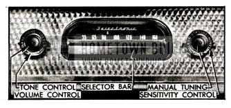
1955 Buick Receiver Controls-Selectronic Radio
When a rear seat speaker is installed, a separate speaker selector switch is mounted on left side of instrument panel. The fully counterclockwise position of selector switch knob turns on the rear speaker only, the midway position turns on both speakers, and the fully clockwise position turns on the front speaker only.
Push Button Tuning Operation – 1955 Buick Sonomatic Radio
To tune in the station for which the push button is set simply push the button in as far as possible. The button will move easily at start, then a slightly harder push is required to complete the travel. At end of button travel the tuner will move to the station for which the button has previously been set as described in paragraph 11-3 (b).
Selective Tuning Operation – 1955 Buick Selectronic Radio
NOTE: To insure adequate sensitivity for selective tuning of the 1955 Buick Selectronic radio it is necessary to have antenna fully extended.
With the 1955 Buick radio turned on, selective tuning of available stations is accomplished by depressing either the selector bar below the dial (fig. 11-1), or the foot control switch on toe panel to left of the brake pedal.
When the bar or switch is fully depressed and released the tuner will automatically move to the right and stop, accurately tuned, when it reaches the next station having adequate strength to stop it. The tuner will stop at a station having adequate strength even though the volume control is not turned up high enough for the station to be audible.
When the tuner reaches the right end of the dial it flies back to the left end and again starts moving to the right until it reaches a station having sufficient strength to stop it. By holding the selector bar or foot control switch down, unwanted stations or areas of the dial can be quickly passed over.
The number of stations on which the tuner will stop in selective tuning can be regulated by manual setting of the sensitivity control knob, which is located behind the manual tuning knob to right of the dial. See figure 11-1. This is a step control having four positions. This control is in the circuit only while the tuner is seeking and does not affect the “on station” sensitivity of the receiver.
Turning the sensitivity control knob clockwise, in the direction of arrow marked “MORE,” increases the number of stations that can be tuned in. Turning knob counterclockwise, in direction of arrow marked “LESS,” decreases the number of stations by eliminating those having weak signal strength in the area where car is located. In the extreme “LESS” position of control knob the tuner usually will stop on the strong local stations only.
If the Selectronic tuner is operated in certain localities or in certain types of buildings where a strong signal is not available, the tuner will automatically search the band from one end to the other without stopping until the sensitivity control knob is turned clockwise to include more stations, or until the 1955 Buick radio is turned off.
Manual Tuning Operation
The manual tuning knob is to right of the dial. See figure 11-1. On the 1955 Buick Sonomatic radio, this knob may be used to tune in stations other than those for which the push buttons are set; it is also used when tuning to set the buttons for selected stations. On the 1955 Buick Selectronic radio, the tuning knob may be used to tune in stations that are too weak to stop the electronic tuning mechanism.
When tuning manually, and particularly when setting up a station on one of the Sonomatic push buttons, careful adjustment of the tuning knob is essential to good radio reception.
On 1955 Buick Sonomatic radio, if the program sounds screechy or distorted, it is probably caused by improper tuning and can be corrected by adjusting the tuning knob slightly. Since the low notes are more affected by tuning than the high ones, it is a good plan to tune the set to a point where the low notes are heard best and high notes are clear but not screechy. Turning the control knob back and forth until the station is almost lost on either side will enable the operator to hear the difference in reception and select an intermediate position giving best results.
11-2 1955 BUICK RADIO TROUBLE DIAGNOSIS ON CAR
The trouble diagnosis information in this paragraph is of a non-technical nature. It is intended as an aid in locating minor faults which can be corrected without a specialized knowledge of 1955 Buick radio and without special radio test equipment. If the suggestions given here do not affect a correction, further testing should be done only by a trained radio technician having proper test equipment.
1955 Buick Radio Is Inoperative or “Dead”
- Turn on the 1955 Buick radio. The dial should light and the vibrator should buzz.
- If dial does not light, disconnect the “A” lead cable and check the fuse located in the receptacle. If fuse is blown it indicates a sticking vibrator; replace fuse and check vibrator, step 3. If fuse is okay check “A” lead cable for proper connection to No. 1 terminal of lighting switch and check cable for open circuit. If source of trouble has not been found, remove receiver for test by a trained radio technician.
- If vibrator does not buzz when fuse is okay, remove receiver cover and tap the vibrator. If vibrator starts after tapping, or after installation of a new fuse, let it run for about 15 minutes and then check for any tendency of vibrator to stick by turning 1955 Buick radio on and off repeatedly.
Replace the vibrator if it will not start or has a tendency to stick. Replace vibrator if it buzzes unevenly or is exceptionally loud.
- If fuse, vibrator, and tubes are satisfactory, substitute a test antenna consisting of a piece of wire about 10 feet long connected to a standard antenna lead-in cable. Place test antenna outside and away from the car. If 1955 Buick radio operates near normal with substitute antenna, some part of car antenna or lead-in is at fault.
Lead-in wire may be checked for “grounds” by removing lead-in cable connector from radio receiver and checking with an ohmmeter from connector tip to car body. This check should show an entirely “open” circuit. CAUTION: Do not check with a lamp or any device drawing current, since the conductor inside loom is only .010″ in diameter and will burn off easily if grounded.
- If source of trouble has not been found remove the receiver and check the tubes by replacing one at a time until the bad one is located, or test the tubes with a reliable checker if available.
- If 1955 Buick radio is still inoperative it should be tested by a trained radio technician.
1955 Buick Radio Reception Is Weak
- Fully extend the antenna and turn on 1955 Buick radio. Turn volume control to maximum position and tune across the dial.
- If reception seems just slightly weak, tune in a station having good volume for listening and grasp the antenna rod with your hand. If volume increases adjust the antenna trimmer (par. 11-3). If volume decreases proceed with the following steps.
- Substitute a test antenna as described in subparagraph a, above.
- Drop the receiver and check for weak tubes by replacing one at a time until the faulty one is located, or test the tubes with a reliable checker if available. If this does not reveal source of trouble, remove the receiver for test by a trained radio technician.
1955 Buick Radio Noisy with Car Standing Still
- Close and securely latch hood before checking for noise.
- Start engine, turn on 1955 Buick radio and tune radio to a spot between stations. Engine noise will usually appear in radio as a clicking sound that varies in frequency with speed of engine. If noise is present disconnect antenna lead-in cable from receiver.
- If engine noise stops when antenna is disconnected, check all high tension wires for full seat in sockets of coil and distributor cap. Check distributor rotor (resistance type) by substituting a known good one.
- If distributor rotor does not correct the noise, check antenna lead-in cable shield and motor lead shield (electric antenna) for proper ground (par. 11-4).
- If engine noise continues with antenna disconnected, check ignition coil and generator capacitors for clean, tight connections; also check the bond strap between engine and cowl to make sure that it has clean tight connections at both ends. Observe generator armature and brushes; if sparking is excessive, check for open armature.
- If source of noise has not been found, replace ignition coil and generator capacitors with known good ‘ones. Ignition coil capacitor lead must be attacked to battery terminal of coil. Generator capacitor lead must be connected to “A” terminal of generator. Regulator capacitor must be connected to “BAT” terminal of regulator. All capacitors must have clean metal ground contact.
1955 Buick Radio Noisy with Car Moving at High Speed
- Turn on 1955 Buick radio and check for engine noise as described in subparagraph c above. If engine noise is present, correct as outlined.
- Drive over different types of roads, especially macadam, with 1955 Buick radio on and tuned between stations. Listen for presence of wheel or tire static. In mild form this static shows up as a click in radio that increases with speed; when more severe it shows up as heavy static or a constant roar. The surface of the road determines the strength of static discharge. Wheel or tire static very seldom occurs on dirt or gravel roads.
- If wheel or tire static is present, apply brakes lightly and if noise decreases check front wheels to see that static collectors have been properly installed and make sure that all grease has been wiped off contacts.
- In certain cases of wheel or tire static, the front wheel static collectors alone may not completely eliminate all noise from this source.
Static Eliminator Powder, available through G.M.P.D. parts warehouses under Group 9.674, may be used in cases where proper conditioning of static collectors does not remedy tire static. An injector for installing the powder is also available under the same group number. This powder equalizes the positive and negative charges developed by the tire, thus neutralizing the corona effect and eliminating radio interference difficulties from this source.
1955 Buick Radio Noisy on Rough Road
- Turn on 1955 Buick radio and check for engine noise as described in subparagraph c above. If engine noise is present, correct as outlined.
- Jar the receiver by striking the case with heel of hand, or a rubber mallet. If this produces noisy reception, remove receiver cover and tap each tube with handle of screwdriver until noisy tube is found. Make sure that all tubes are firmly pressed into sockets. If this does not correct the noise, remove- receiver for test by a trained radio technician.
- If noisy reception is not produced when receiver is jarred, fully extend antenna and turn 1955 Buick radio volume control on full. If noise appears in speaker check antenna and lead-in wire for loose connections. If wiggling lead-in does not cause noise, rap antenna rod with insulated end of screwdriver; if noise then appears, check antenna for shorting to car body or corrosion between antenna sections.
1955 Buick Electric Antenna Operates Too Slow
- If operation of 1955 Buick antenna to full up or down position is slower than 12 seconds check for dirty, corroded, or bent antenna sections.
- If 1955 Buick antenna sections are clean and straight and operation is still too slow, check all wiring including_ ground connections to cowl; also check for defective control switch.
- If cause of slow operation has not been found, remove antenna and check for defective tube and nylon assembly or defective motor.
1955 Buick Electric Antenna Does Not Operate
- If 1955 Buick antenna fails to operate and motor does not operate as indicated by deflection on charge indicator, then check fuse, all wiring including ground connection to cowl; also check for defective control switch.
- If motor still does not operate, or new fuse blows out, either the motor or its leads are faulty and must be repaired or replaced.
- When motor operates but antenna will not raise or lower, then check for dirty corroded or bent antenna sections.
- If antenna still fails to operate it will be necessary to remove antenna from car, disassemble large body tube from motor assembly and check for defective antenna tube and nylon assembly, or defective motor.
11-3 1955 BUICK RADIO ADJUSTMENTS – ON CAR
When making the adjustments covered in this paragraph it is essential to have the car in a location that is as free as possible from outside interference.
Antenna Trimmer Adjustment
An antenna trimmer adjustment is provided for matching the antenna coil in the receiver to the car antenna. This adjustment must always be made after installation of receiver and antenna, or after any repairs to these units. The adjustment should also be checked whenever the 1955 Buick radio reception is unsatisfactory.
- Raise 1955 Buick antenna to maximum height.
- Tune 1955 Buick radio to a station between 600 and 1000 K.C. that can barely be heard with volume turned full on.
- Insert a screwdriver through the opening in left side of receiver adjacent to the lead-in cable (fig. 11-2) and carefully turn the trimmer screw back and forth until a position is found that gives maximum volume.
1955 Buick Receiver Installation
Setting Push Buttons to Desired Stations
- Turn on the 1955 Buick radio.
- Pull button to right and all the way out.
- Carefully tune in the desired station manually, then push the button all the way in.
- Move dial pointer away from the selected station and push the button to make certain the station will be properly tuned in.
- Turn tuning knob back and forth to make certain that best tuning is obtained with the push button. If best tuning is not obtained, repeat steps 2, 3, 4.
11-4 1955 BUICK RADIO INSTALLATION INSTRUCTIONS
If 1955 Buick radio parts are removed from car for any reason, the following instructions must be carefully observed to insure proper reinstallation and satisfactory operation. These instructions cover reinstallation only; if an original installation is to be made carefully follow instructions contained in the parts package, particularly with reference to cutting holes in sheet metal and trim.
IMPORTANT: The standard Buick antenna is matched with the receiver within the range of the trimmer adjustment. Other antennas may not match the receiver within the range of the trimmer adjustment; therefore the use of other than a standard Buick antenna is not recommended.
Installation of 1955 Buick Receiver
- Cover the push buttons or selector bar with friction tape to prevent damage while installing receiver.
- If rear seat speaker is used, remove back cover of receiver and insert the two-wire cable from the speaker selector switch through a vent hole in bottom of receiver, pushing the rubber grommet into place in vent hole. Connect wires to the receiver and reinstall receiver cover.
CAUTION: Carefully support receiver until it is installed, to avoid straining the wire connections to speaker selector switch.
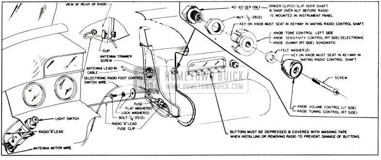
- On Series 40-60, install spacer clip over each control shaft bushing and snap clip over the nut. See figure 11-2.
- Install receiver by sitting in front seat and holding receiver at arm’s length while the two threaded bushings are inserted through control holes in instrument panel. Install and tighten hex nuts on bushings.
- Start cap screws with lockwashers and large flat washers into both sides of receiver through slotted holes in support brackets, then pull receiver so that rubber gasket at speaker opening is compressed against instrument panel, and tighten cap screws securely.
- Install tone control knob and volume control knob with felt washer on shaft to left of the dial. Install dummy knob (Sonomatic) or sensitivity knob (Selectronic) and tuning control knob with felt washer on shaft to right of dial. See figure 11-2.
CAUTION: Make sure that keys on outer knobs properly engage keyways in control shafts and that knob retaining screws are properly started. Do not tighten screws excessively.
- Connect the “A” lead cable to one of the No.1 (end) terminals of lighting switch. Never connect to any other terminal. Install proper fuse (par. 10-5, b) in fuse holder and connect “A” lead cable to lead at left lower corner of receiver. Install fuse holder in clip on support bracket. See figure 11-2.
- Connect antenna lead-in wire to receiver, then make antenna trimmer adjustment (par. 11-3).
- If Selectronic foot control was disconnected or removed, reinstall with cable running up behind left edge of steering column pad. Plug cable into receiver and attach it to clip on receiver cover. See figure 11-2.
Installation of Interference Suppression Parts
Figure 11-3 shows proper installation of the capacitor on generator and figure 11-4 shows proper installation of the capacitor on generator regulator, to prevent interference caused by these units.
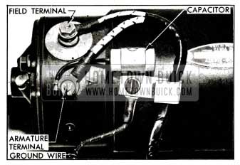
1955 Buick Capacitor Mounted on Generator
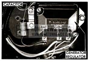
1955 Buick Capacitor Mounted on Generator Regulator
Note that the capacitor lead is connected to the armature (“A”) terminal of generator and to the “BAT” terminal of regulator. Capacitors must never be connected to the field (“F”) terminal of either unit as this will cause bad pitting of the voltage regulator points, thus preventing it from operating properly.
The standard distributor rotor contains a 10,000 ohm resistor which eliminates the suppressor formerly installed on the coil-to-distributor high tension wire.
The coil capacitor is mounted on the coil bracket and the lead is connected to the battery positive (+) terminal of coil. See figure 10-47. If capacitor is connected to the distributor negative (-) terminal excessive pitting of distributor contact points will result.
A static collector is installed in each front wheel hub grease cap. For good results the grease cap and the center of steering knuckle spindle must be clean and free from grease. The center of static collector is made of self-lubricating material.
In addition to the items mentioned above, a bond strap is connected between the cowl and the right rear corner of the engine.
Installation of 1955 Buick Manual Antenna
- When 1955 Buick antenna is being installed on a new fender, make a template from the old fender to properly locate the hole for the body tube. A template may be obtained from an antenna parts package, if available.
- Remove burr from hole cut in fender and clean under surface of fender around hole for good ground contact of antenna, then insert pad in hole.
- Loosely assemble 1955 Buick antenna mounting support to inner face of bracket.
- Connect antenna lead-in cable to the antenna assembly, tighten securely, then insert antenna assembly through pad from under fender, with antenna lead-in connector pointing toward front of car. NOTE: Do not use soap or grease in this operation. See figure 11-5.
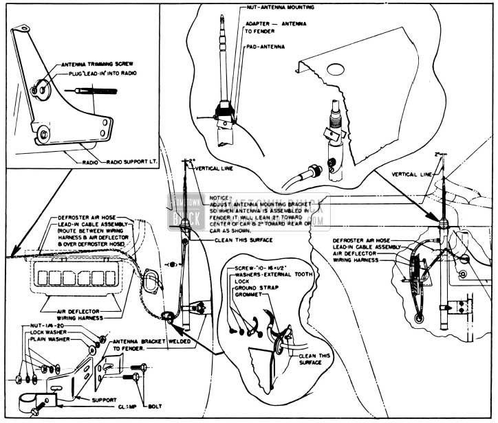
1955 Buick Manual Antenna Installation Details
Installation of 1955 Buick Electric Antenna
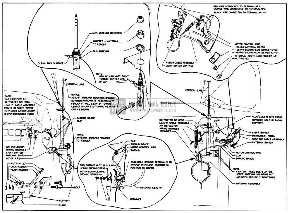
1955 Buick Electric Antenna Installation Details
Figure 11-6 shows all necessary details for reinstalling the electric motor driven antenna. The installation procedure is very similar to that described for manual antenna (Subpar. c) except for the following points.
- When inserting the 1955 Buick antenna into the fender the top ground arm must be pointing toward the center of car.
- Bring the motor wire through grommet in cowl with the lead-in cable and attach both ground leads to cowl with a 10-16 x 1/2″ tapping screw, with internal lockwashers on both sides of terminals.
- Snap clip on to bottom edge of diagonal cowl brace and place motor wire in clip.
- Connect black wire to No. 1 terminal, orange wire to No. 2 terminal, fuse and cable assembly to No. 3 terminal of antenna control switch.
- Insert 1955 Buick antenna switch into hole in lower flange of instrument panel and install escutcheon, lockwasher and nut.
- Connect fuse and cable assembly to lower rear (No. 1) terminal of lighting switch.
- Check antenna for travel time from fully retracted to fully extended positions. If time is more than 12 seconds check connections at both switches. If antenna still operates too slow, or is inoperative, refer to paragraph 11-2 (subpar. f, g).
Reinstallation of 1955 Buick Rear Seat Speaker
If 1955 Buick rear seat speaker is removed for any reason, be sure to reinstall the speaker, fiber board, screen, and bezel as shown in figure 11-7.
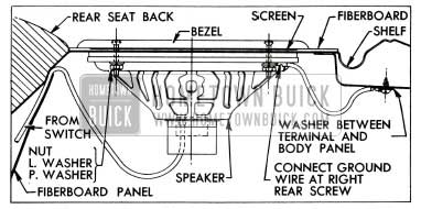
1955 Buick Rear Seat Speaker Installation
Place one terminal of the black ground wire under the right rear speaker mounting nut. The other end of ground wire is attached to adjacent body metal panel with a screw and a shake proof washer placed between terminal and body panel.
11-5 1955 BUICK RADIO SERVICE PARTS ALIGNMENT PROCEDURES
Service Parts
Service parts for 1955 Buick radios are marketed through United Motors Service and are listed in auto radio bulletins obtainable through U.M.S. branches.
Alignment Procedures
The 1955 Buick radio receiver should be functioning before the various aligning adjustments are made. Trouble shooting, if necessary, should precede the final adjustment. Under no circumstance should alignment be attempted without calibrated test oscillator and output meter, or by untrained personnel.
The alignment procedures must be rigidly adhered to and all adjustments must be made in the order given.
1955 Buick Sonomatic Radio Alignment Procedure
This procedure applies only to the Model 981651 radio. See figure 11-10 for location of the adjustment screws indicated.
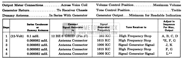
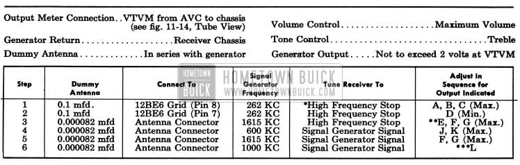
1955 Buick Sonomatic Radio Alignments
*Before making this adjustment check mechanical setting of oscillator core “H.” The rear of the core should be 1 25/32” from the mounting end of the coil form. (This measurement is readily made by inserting a suitable plug in the mounting end of the coil form.) Core adjustments should be made with an insulated screw driver, and core studs should be cemented in place with glyptal or household cement after alignment.
**Lis the pointer adjustment screw which is on the connecting link, between the pointer assembly and the parallel guide bar. It should be adjusted so that the dial pointer corresponds with the 1000 KC mark on the dial. (On first “0” of “100.”)
With the 1955 Buick radio installed and the car antenna plugged in adjust the antenna trimmer “G” for maximum volume with the radio tuned to a weak station between 600 and 1000 KC (see sticker on case).
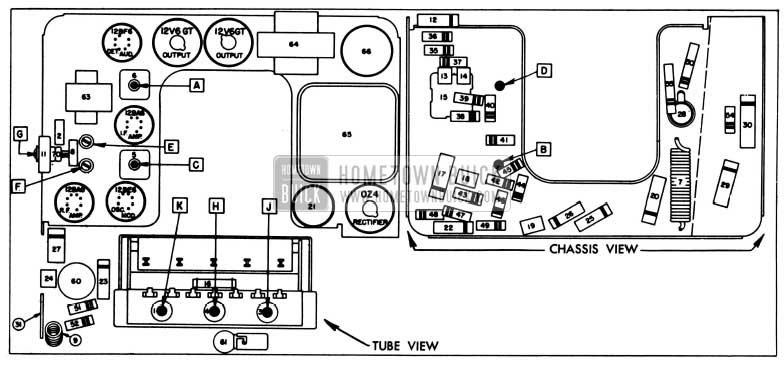
1955 Buick Sonomatic Radio Parts Layout
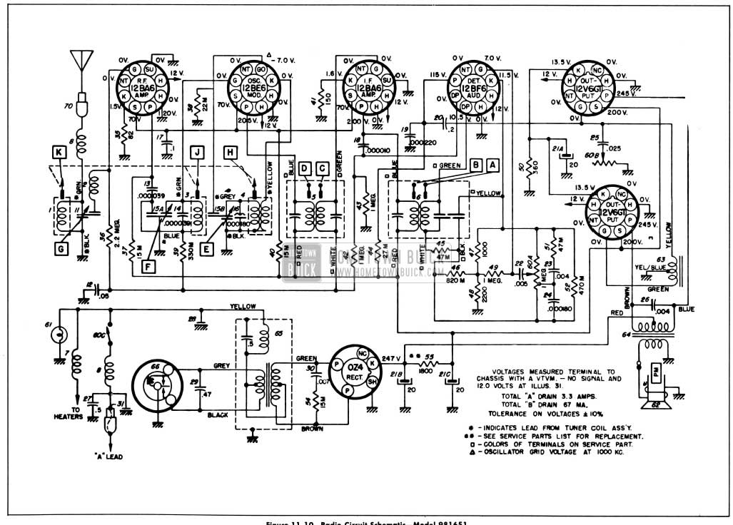
1955 Buick Sonomatic Radio Circuit Schematic
1955 Buick Selectronic Radio Alignment Procedure
This procedure applies only to the Model 981652 radio. See figure 11-11 for location of the adjustment screws indicated.
1955 Buick Selectronic Radio Alignments
NOTE: When aligning, be sure to use a vacuum tube voltmeter as indicated and be sure to follow the alignment sequence given-(Notice that the primary of the 2nd. l.F. is aligned first).
*To tune to high frequency, put a 0.070″ feeler gauge (or bare #13 wire) in slot against the high frequency stop. Depress station selector bar and allow the planetary arm to run against the feeler gauge. Turn the 1955 Buick radio off and then back on.
**Before making this adjustment, check the setting of oscillator core “H.” The rear of the core should be 1 25/32″ from the mounting end of the coil form. This measurement is readily made by inserting a suitable plug in the mounting end of the coil form. The core adjustment is made from the mounting end of the coil form with an insulated screwdriver. (It will be necessary to steady the core guide bar while making these adjustments. This can be done by applying a downward pressure on the guide bar at the antenna coil end.) If this adjustment is necessary, first dissolve the glyptal seal on the core stud and be sure to re-seal after making the adjustment.
***”L” is the pointer adjustment screw on the end of the core guide bar-adjust so pointer reads 1000 KC.
With the 1955 Buick radio installed and the antenna plugged in, adjust the antenna trimmer “G” for maximum volume with the radio tuned to a weak station between 600 and 1000 KC (see sticker on case).
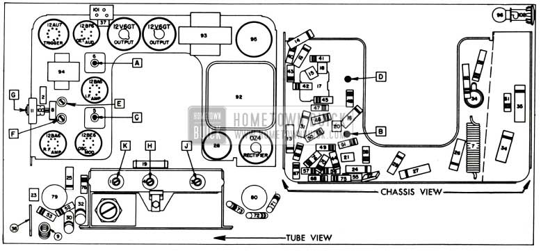
1955 Buick Selectronic Radio Parts Layout
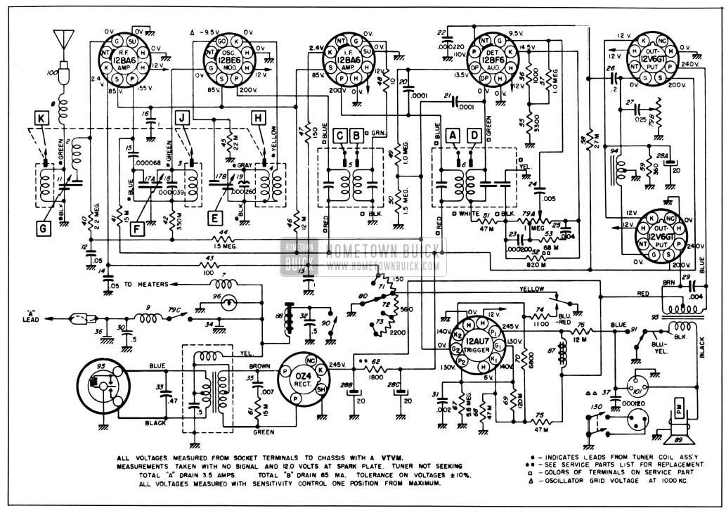
1955 Buick Selectronic Radio Circuit Schematic
Leave A Comment
You must be logged in to post a comment.