GROUP 4 – 1953 BUICK CLUTCH, TRANSMISSION, UNIVERSAL JOINT
NOTE: For 1953 Buick clutch and transmission information not listed above refer to Group 4 of the 1952 Buick Shop Manual.
4-1 1953 BUICK CLUTCH AND TRANSMISSION TYPES
A synchromesh transmission and single plate clutch are standard equipment on Series 40 and 50, and the Dynaflow transmission is optional in both series. The Dynaflow transmission is standard equipment on Series 70 and the synchromesh transmission is not available in this series.
1953 Buick Clutch Types
1953 Buick Series 40 uses the single plate clutch with “crown” type spring that has been used in past Series 40-50 models. For description and all service information on the 1953 Buick clutch refer to Section 4-A in the 1952 Buick Shop Manual.
1953 Buick Series 50 uses the single plate clutch with release levers and coil type springs that was used on 1948 Series 70 models. For description and all service information on this clutch refer to Section 4-A in the 1948-49 Bu ick Shop Manual.
1953 Buick Synchromesh Transmission Types
1953 Buick Series 40 uses the same transmission that has been used in past Series 40 -50 models. For description and service information on this transmission refer to Section 4 -B in the 1952 Buick Shop Manual.
1953 Buick Series 50 uses the same transmission that was used in the 1948 Series 70 models, except that the rear bearing retainer and main shaft are longer because of application to the V-8 engine. For description and service information on this transmission refer to Section 4-C in the 1948-49 Buick Shop Manual.
1953 Buick Dynaflow Transmission Types
All series use the same basic “Twin Turbine” Dynaflow transmission, which is modified in several details for application to the Series 40 8-in-line engine or the Series 50-70 V-8 engine. The 1953 Buick “Twin Turbine” transmission has a completely new 4 -element torque converter which features two turbines interconnected through a simple planetary gear set. This converter is completely d escribed in paragraph 4-2.
Compared with previous models, the Twin Turbine converter has one pump in place of a primary and secondary pump, one stator in place of two, and consequently only one freewheeling clutch (in stator) instead of three. The new reaction shaft is shorter and the input shaft and bell housing have been changed to accommodate new converter parts.
Except for the torque converter and related parts, the Series 40 transmission is the same as used in 1952. For application to the V-8 engine used in Series 50-70, the Dynaflow transmission installation includes the following changes from the Series 40.
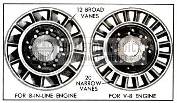
- A converter stator with 20 blades, compared to 12 blades in Series 40, which adapts the converter to the torque characteristics of the V-8 engine.
- Planet carries output shaft and rear bearing retainer 5 3/4″ longer the Series 40.
- Access hole and cover (breather) added for adjustment of valve operating rod.
- Speedometer driven gear located higher.
- Oil cooler mounted under the rear bearing retainer.
- New shift lever, range indicator, lever and roller type detent, and stop plate in steering column.
Refer to Sections 4-C, 4-D, and 4-E of the 1952 Buick Shop Manual for all Dynaflow service information not given in the following paragraphs which cover new features only.
1953 Buick Universal Joint and Torque Ball
The 1953 Buick universal joint oil seal has been removed from the torque ball and a new seal has been placed in the front end of the torque tube. Otherwise, the universal joint and torque ball is similar to the 1952 construction. Refer to paragraph 4-12 in the 1952 Buick Shop Manual for adjustment of torque ball.
1953 Buick Speedometer Gears
A 7-tooth speedometer driving worm gear is used in transmissions of all models equipped with the first type differential carrier described in paragraph 5-l. An 8-tooth worm gear is used in transmissions of all models equipped with the second type differential carrier. The speedometer gear tooth combination for the various rear axle gear ratios are as follows:
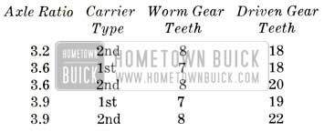
1953 Buick Speedometer Gears
4-2 1953 BUICK DYNAFLOW TWIN TURBINE TORQUE CONVERTER
The 1953 Buick Dynaflow torque converter is connected to the engine flywheel and serves as a hydraulic coupling through which engine torque (turning force) is transmitted to drive the car. The torque converter steps up or multiplies the engine output torque whenever car operating conditions demand greater torque than the engine can supply. In this respect it serves the same purpose as the selective reduction gears used in other types of automotive transmissions.
Torque multiplication is always required when a car is started and accelerated at low speeds. Torque multiplication may be required when car is ascending steep grades, moving in deep sand, snow, etc. Torque requirements decrease as the ca r gains momentum and when a point is reached where engine torque is adequate, no torque multiplication is required. From this point, torque multiplication would be undesirable and uneconomical since it is always obtained at a sacrifice in speed.
The Dynaflow torque converter automatically provides the proper ratio of torque multiplication to meet the varying demands imposed by starting and driving under all ordinary conditions of load and grad e. The transition through the various ratios of torque multiplication is smooth and devoid of steps or change points since it is accomplished without the use of selective gears.
The principle elements of the “Twin Turbine” torque converter are described in subparagraphs a, b, c, and the operation of these elements is described in subparagraph d.
1953 Buick Converter Pump and Cover
The 1953 Buick converter pump is bolted to the engine flywheel so that it rotates whenever the engine is running. The pump and the cover which closes its front end form a housing for all other converter components, and this housing is kept filled with oil.
The pump is similar to the impeller of a conventional centrifugal pump but it is shaped so that it discharges fluid in a different direction. A conventional pump impeller picks up fluid at its center and discharges fluid from its rim at approximately 90 degrees to its axis of rotation. Due to the curved form of the blades and the supporting shells, the converter pump discharges oil in a direction approximately parallel to its axis of rotation and in the form of a spinning hollow cylinder. See figure 4-1.
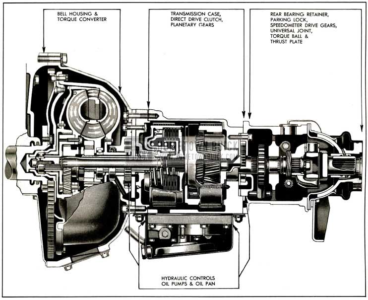
1953 Buick Dynaflow Transmission-Series 40
The function of the converter pump assembly is to convert engine torque into an energy transmitting flow of oil with which to drive the converter turbine, into which the oil is projected from the pump.
1953 Buick Twin Turbine Assembly
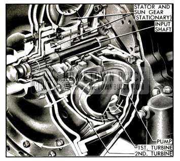
The turbine assembly is coupled to the transmission input shaft through which torque is transmitted to the direct drive clutch and the planetary gears located to rear of the torque converter. The twin turbine assembly consists of a first turbine, a second turbine, and a planetary gear set that connects the first turbine to the second turbine and the transmission input shaft. See figure 4-2.
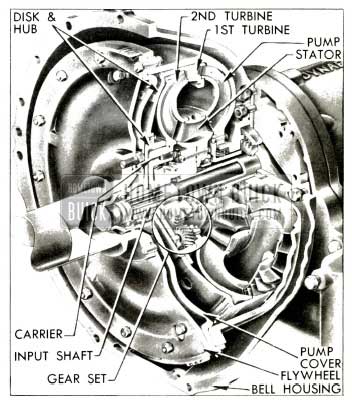
1953 Buick Twin Turbine Torque Converter
The first turbine has a narrow band of vanes located between the pump exit and the second turbine, in position to receive the spinning cylinder of oil projected from the pump. The second turbine is located inside the first turbine in position to receive all oil that flows through it from the pump. This turbine has a broad band of vanes which are shaped to direct the oil flow back into the stator in a direction opposite to convertor rotation.
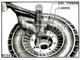
The second turbine is bolted to a turbine carrier which is splined to the input shaft, therefore the second turbine and shaft rotate at the same peed. The first turbine is mounted on a disk and hub assembly which has a bearing on the hub of the turbine carrier. This turbine is connected to the carrier and input shaft through the planetary gears, therefore its speed relative to the input shaft is governed by gear action. See figure 4-3.
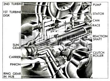
1953 Buick Turbine Planetary Gears and Converter Stator
The first turbine hub contains internal ring gear teeth which mesh with four planet pinions mounted in the turbine carrier on steel pins and needle bearings. The planet pinions mesh with a sun gear which is supported by a bearing on the input shaft. The sun gear is coupled to the stator free wheel cam so that the gear is held stationary whenever the stator is held stationary by the free wheel clutch. See figure 4-3.
The function of the turbine assembly is to absorb energy from the oil projected into it by the pump and to convert the energy into torque with which to drive the rear wheels.
1953 Buick Converter Stator
The single stator is located between the second turbine exit and the converter pump entrance. It is supported by freewheeling clutch rollers upon a race or hub which is splined to a stationary reaction shaft. The shaft is anchored to a flange bolted between the bell housing and the transmission case. See figure 4-3.
The stator vanes have curved surfaces which control the flow of oil between second turbine exit and pump entrance when the turbine is stationary or at low speed relative to the pump. Oil then leaves the turbine with considerable energy but spins in a direction opposing pump rotation. The stationary stator vanes alter the direction of flow so that oil approaches the pump at proper angle to enter without opposing pump rotation.
As the turbine approaches pump speed the direction of oil flow changes until it no longer opposes pump rotation. The stator then free wheels so that it will not interfere with efficient flow of oil between turbine and pump.
When the transmission is used with the Series 40 8-in-line engine the stator has 12 broad vanes; when used with the Series 50-70
V-8 engine the stator has 20 narrow vanes. This difference in stator design adapts the one converter to the different output torques of the two engines. See figure 4-4.
1953 Buick Two Types of Stators
The function of the stator, when stationary, is to change the direction of oil flow from the turbine to the proper angle for smooth entrance into the converter pump, so that all energy remaining in the oil may be utilized to increase pump output.
Operation of 1953 Buick Twin Turbine Torque Converter
Operation of the 1953 Buick torque converter is the same in Direct Drive, Low and Reverse. The converter transmits torque to the direct drive clutch and planetary gears through the transmission input shaft. The range of transmission operation is determined by control of the clutch and gears as described in paragraph 4-21 of the 1952 Buick Shop Manual.
Description of torque converter operation will begin with the car stationary, transmission in Direct Drive, and engine running at idling speeds. At this point the converter pump is slowly turning with the engine and the turbine members are stationary.
The engine driven converter pump projects a rotating cylinder of oil into the first turbine, through which it flows into the second turbine. At idling speed the force of oil flow against the vanes is not sufficient to move either turbine, therefore, the oil flows through the turbines into the stator without transmitting any appreciable amount of torque.
As the oil emerges from the second turbine near its center, the backward curvature of the exit ends of the vanes causes the oil to spin backward with reference to pump rotation as it flows into the stator. Pressure of oil against the forward face of the stator vanes causes the freewheeling clutch to lock and hold the stator (and sun gear) stationary. The curved stator vanes then change the direction of flow so that the oil enters the pump rotating in the same direction as the pump is turning. See figure 4-5.
1953 Buick Turbine and Gear Operation
While the engine is running at idling speeds the oil continues to flow from the pump, through the turbine and stators, and back into the pump in the circuit just described. A gentle circulation is created which does not transmit appreciable torque, although a light movement or creep of car may sometimes be produced.
When the throttle is open the engine speeds up and rapidly approaches its torque peak. With increased speed, the converter pump now projects a large volume of oil into the turbines at high rotary speed. The rotating cylindrical mass of oil may be compared to a spinning flywheel rim. A spinning flywheel has stored up energy (turning force) which may be transmitted to any mechanism which opposes its rotation. Since the vanes of both turbines oppose rotation of the spinning flywheel of oil projected from the pump the stored up energy in the oil exerts a powerful impulsion force against the vanes tending to rotate the turbines in the same direction as the pump.
At this stage the impulsion force of the oil against the vanes is not sufficient to move either turbine. The oil flows through the turbine channels and is discharged into the stator, which redirects it into the pump entrance. As the oil emerges from the second turbine into the stator, spinning at high speed in a reversed direction, it exerts a powerful reaction force against the turbine vanes, tending to rotate the turbine in the same direction as the pump.
Engine torque applied to the converter pump generates a given amount of energy in the oil projected from the pump against the turbine vanes. When the turbines are stationary, the oil passes through both turbines and the stator and returns to the pump with almost as much energy as when projected. The amount of energy in the oil thereafter projected from the pump becomes the sum of the energy in returning oil plus the energy resulting from engine torque application, or almost double the amount of energy that could be generated by engine torque alone. The greatly increased energy in the spinning flywheel of oil then projected into the turbines produces a corresponding increase in the impulsion and reaction forces upon the turbine vanes.
The described build-up of forces produces a turning force or torque upon the turbines which is much greater than the torque produced by the engine; therefore, torque multiplication is accomplished. It would seem that torque multiplication would increase indefinitely as the cycle repeats itself, but mechanical factors limit the increase in torque multiplication beyond a definite ratio in any given torque converter design.
The build-up of forces against the turbine vanes causes the first turbine to rotate in the same direction as the converter pump. The first turbine absorbs part of the energy transmitted by the oil stream and converts this energy into torque, which is imparted to the ring gear in its hub. The ring gear rotates the planet pinions, causing them to “walk” around the stationary sun gear so that turning force is applied to the turbine carrier in which the pinions are mounted. The second turbine absorbs energy from the oil stream after it leaves the first turbine and converts this energy into torque which is also imparted to the turbine carrier, on which this turbine is mounted. The turbine carrier transmits the torque of both turbines to the input shaft to which it is splined. See figure 4-5.
The turbine planetary gear set gives a ratio of 1.6 to 1 when the sun gear is stationary and this reduction gearing increases the torque transmitted through the first turbine. The overall operation of the Twin Turbine Converter provides a maximum torque multiplication of approximately 2.45 to 1 at stall (car stationary and engine accelerated under load). Usually the car may be started with appreciably less than the maximum torque multiplication that is available through the converter. For unusually severe conditions the Low Range may be used to provide an overall maximum torque multiplication of approximately 4.46 to 1 at stall.
As the car gains speed and momentum the demand for torque decreases so that the applied torque causes turbine speed to rapidly approach pump speed. As this occurs it is essential for torque multiplication to taper off so that car speed can be maintained at a lower, more economical engine speed. Tapering off occurs automatically because centrifugal force generated in the rapidly rotating mass of oil in the turbines creates an outward counter force which opposes the flow of oil from the pump. Reduction of oil flow and pump output energy effects a decrease in the impulsion and reaction forces upon the turbines so multiplication of engine output torque tapers off as turbine speed increases.
Reduction in speed differential between turbines and pump reduces the torque reaction on the sun gear until this reaction is entirely eliminated. As speed of the second turbine increases, the direction of oil flow into the stator correspondingly changes toward the rear faces of the stator vanes, thus gradually eliminating the force holding the stator stationary.
Pressure against the forward face of the stator vanes and torque reaction against the sun gear ceases at approximately the same speed, after which the stator and gear free wheels. When the sun gear is released by the stator freewheeling clutch the first turbine ceases to be effective. The speed of the second turbine increases until both turbines are rotating at nearly the same speed as the pump. During this same period the speed of the freewheeling stator and sun gear increases and approaches turbine speed so that these parts present little or no interference with the flow of oil between the second turbine and the pump.
At this point the torque converter functions as an efficient fluid coupling, transmitting torque at a 1 to 1 ratio. Sufficient speed differential remains between pump and turbines to enable transfer of oil from pump to turbines where the oil gives up energy and returns to the pump for recirculation.
The various stages of stator and pump operation described do not occur at set speeds but are dependent on torque requirements imposed by car operating conditions. With light load and steady driving, torque multiplication may cease at very low car speeds, but with continued acceleration some degree of torque multiplication may be present throughout the major portion of the car speed range. When the torque converter is operating as a fluid coupling and car operating conditions change so that increased torque is demanded, the converter automatically adjusts itself to meet the demand without any manipulation of controls by the driver.
When the drive through the torque converter is reversed on deceleration or when descending grades, the converter functions as a fluid coupling to permit effective engine braking. It also functions as a fluid coupling when the car is pushed in Low range to crank the engine.
4-3 1953 BUICK DYNAFLOW MANUAL CONTROL MECHANISM AND LINKAGE ADJUSTMENTS
NOTE: Series 50-70 only. For Series 40 refer to paragraph 4-26 of the 1952 Buick Shop Manual.
Control Mechanism in Steering Column
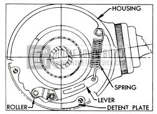
The control lever housing is externally mounted on the upper end of the steering column jacket. The housing contains a spring loaded lever and roller which engages notches in a detent plate anchored to the underside of the signal switch housing. When the control lever rotates the housing and control shaft during shifts, the detent roller moves easily along the notches in the plate but provides a firm detent in the selected position. See figure 4-6.
1953 Buick Detent Lever and Plate
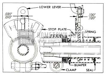
A stop plate is mounted on the column jacket in position to engage a tongue on the control shaft lower lever. The control lever must be raised toward the steering wheel when shifting into Reverse, Neutral or Parking. The control lever raises the control shaft against pressure of a return spring, and this lifts the lower lever clear of the stop plate.
With control lever in “Drive” position, a clearance of .120” to.130″ (1/8”) must exist between the lower lever and stop plate. A clearance of .010″ to .020″ must also exist between the tongue on lever and the nearest edge of the large hole in stop plate. The stop plate may be adjusted as required after loosening the clamp bolt. See figure 4-7.
1953 Buick Lower Lever and Stop Plate
The control lever and related parts may be removed by first unscrewing the lever retainer from housing, then removing the lever cover, retainer spring, retainer plate, and lever. Remove the anti-rattle spring retainer and spring from the control lever stud, then unscrew the stud from control shaft. See figure 4-8.
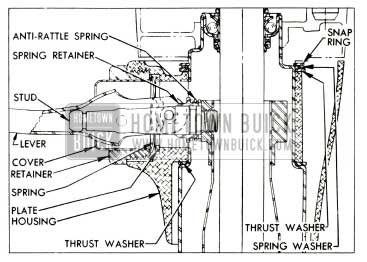
1953 Buick Control Lever and Housing Parts
When the control lever stud is installed in control shaft, it is very important to tighten it to 25-30 ft. lbs. torque. Use a torque wrench equipped with a long 9/16″ socket which has notches cut to fit a piece of 3/16″ (.187″) drill rod inserted through the hole in stud. See figure 4-9.
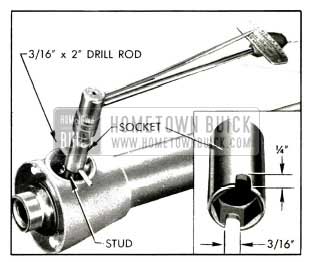
1953 Buick Installing Control Lever Stud
1953 Buick Control Linkage Adjustment
When a 1953 Buick Dynaflow transmission does not operate properly it is advisable to .first check the manual control linkage adjustment, after transmission is warmed up to normal operating temperature and oil is at proper level.
- Park car on ramp or steep grade with control lever in Parking (P) position to determine whether parking lock holds securely. Then let car roll with control lever in Neutral (N) position and listen for a clicking or ratchet noise which would indicate that parking lock pawl is contacting the parking lock ratchet wheel.
- If parking lock fails to hold, or ratchet noise exists in Neutral, adjust shift rod as described in Steps 3, 4, 5; otherwise proceed to Step 6.
- Place control lever in Parking (P) position and disconnect the lower shift rod from shift idler lever by removing clevis pin and spring washer. Pull forward on shift rod and move car slightly to make sure that locking pawl is fully engaged in ratchet wheel. Do not jerk on rod as this may spring linkage in rear bearing retainer.
- Check movement at lower end of transmission shift lever by pushing forward against spring pressure until a definite stop is felt. The spring travel or movement of lower end of lever should be 1/8″ to 3/16″ beyond the Parking (P) position. See figure 4-10.
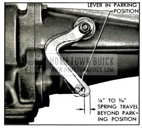
1953 Buick Spring Travel at Shift Lever
If spring travel is not within these limits the control valve operating rod in transmission must be adjusted.
- When spring travel is correct pull shift rod forward until stop is felt then adjust shift rod clevis until clevis pin will just enter hole in shift idler lever, with control detent firmly engaged in Parking (P) position. Lengthen shift rod by unscrewing clevis 3 complete turns, then temporarily connect rod to idler lever with clevis pin.
- With transmission warmed up and engine idling at approximately 600 RPM, slowly move control lever from Neutral (N) to Drive (D) position. The clutch should engage, as indicated by an immediate decrease in engine speed when the tip of dial pointer is midway between “N” and “D” on speed ratio dial.
- Slowly move control lever from Drive (D) position to Neutral (N) position. Clutch should disengage, as indicated by an immediate increase in engine speed, when tip of speed ratio pointer is midway between “D” and “N” on speed ratio dial.
- If points of clutch engagement and disengagement are not as specified adjust shift rod clevis (Steps 3, 4, 5) to obtain required setting, being careful not to change clevis so much that parking lock fails to hold or parking lock pawl contacts ratchet wheel in Neutral ( N) .
- Check operation in Low (L) and Reverse (R). Low and Reverse should be obtained when detents are engaged and the shift points should occur when tip of dial pointer is midway between “L” and “R” on speed ratio dial. If these conditions are not correct, the transmission shift lever may be bent.
- After adjustments are completed, tighten clevis lock nut securely and permanently install clevis pin with spring washer located between shift idler lever and clevis; install cotter pin.
4-4 REMOVAL AND INSTALLATION OF 1953 BUICK DYNAFLOW TRANSMISSION
NOTE: Series 50-70 only. For Series 40 refer to paragraphs 4-27 and 4-28 of 1952 Buick Shop Manual.
Removal of 1953 Buick Dynaflow Transmission
- Hoist front and rear of car and rest it solidly on stands placed under frame. Frame side rail should be at least 20″ above floor.
- Disconnect torque tube from torque ball and move rear axle back to disengage propeller shaft from universal joint.
- Remove cranking motor splash pan, bell housing cover and bell housing hand hole cover.
- Turn flywheel until one converter drain plug can be loosened sufficiently to provide an air vent, then turn flywheel until opposite drain plug is straight down. Remove this plug and allow oil to drain from converter.
- Remove plug from oil pan to drain oil from transmission.
- Disconnect pipes from oil cooler, disconnect cooler from rear bearing retainer and move cooler with attached hoses to a safe place.
- Disconnect oil filler pipe at rubber hose and disconnect exhaust pipe hanger at right accumulator.
- Disconnect shift rod and speedometer cable from transmission.
- Disconnect rubber thrust pad from transmission support by removing three nuts and plate, then lift out shims located between support and thrust pad. Remove two bolts and plate which attach transmission mounting pad to the support.
- Place a suitable jack under rear end of engine lower crankcase so that engine will be safely supported while transmission is removed.
CAUTION: Do not use bar with hooks placed over frame side rails because brake pipes on top of left side rail will be damaged.
- Place transmission jack or hoist in position and adjust it to securely support the transmission in accordance with instructions for the equipment being used.
- Raise the engine and transmission just enough to relieve the load on transmission support, then remove the support from frame X member and remove thrust pad from the thrust plate.
On cars equipped with air conditioning, disconnect discharge and suction lines at the compressor in order to avoid damaging the flexible adapters in these lines when raising or lowering the rear end of engine.
- Mark flywheel, converter pump and cover with daubs of paint so that pump can be reinstalled in same position on flywheel. Disconnect the converter from flywheel.
- Lower the transmission just enough so that bell housing bolts can be reached. With engine and transmission supported by the separate jacks, disconnect the bell housing from engine crankcase.
- Move transmission rearward to disengage hub of converter pump cover from crankshaft, lower transmission and remove it from under car.
Installation of 1953 Buick Dynaflow Transmission
- Turn flywheel so that one hole for converter drain plug is straight down and turn converter so that one drain plug is straight down. Paint marks placed on flywheel, converter pump and cover during removal must be in position to align when transmission is installed.
- Raise transmission into place with same equipment as used for removal. Align converter drain plug and cover bolts with corresponding holes in flywheel before moving transmission forward against flywheel housing.
- Adjust lifting equipment so that bell housing meets the engine crankcase squarely and engages the two dowels, then install all bell housing bolts with lockwashers. Tighten all bolts uniformly to 45-55 ft. lbs. torque.
- Attach thrust pad to thrust plate. Raise transmission far enough to install transmission support then lower transmission until weight is carried by the mounting pad and support. Attach mounting pad to the support with bolt plate and self-locking nuts.
- Remove lifting equipment and engine support jack.
- With engine and transmission resting freely and normally on mounting, install sufficient shims between the thrust pad and the transmission support to fill the existing space. Insert shims from above, then install the bolt plate and three nuts which attach thrust pad to the support.
- Use the shank of a 11/32” drill to align bolt holes in flywheel and converter, install bolts and tighten evenly to 25-30 ft. lbs. torque.
- Check converter drain plugs for tightness, then install bell housing and hand hole covers, and cranking motor splash pan.
- Connect speedometer cable to the driven gear sleeve and connect shift rod to shift lever on transmission.
- Attach exhaust pipe hanger to transmission and connect oil filler pipe to oil pan pipe, with both pipes contacting inside the rubber connector.
- Install oil cooler under the rear bearing retainer and connect the oil pipes.
- Connect torque tube to torque ball with bolts and lockwashers.
- Wipe all oil from outside of transmission then lower car to floor.
- Fill transmission to proper level as described in paragraph 1-4.
- Check adjustment of control linkage (par. 4-3).
- Road test car for approximately 20 miles with frequent stops and starts as might be encountered in heavy traffic. A thorough road warm-up is desired.
- Place car on hoist and carefully examine the transmission and all connections for oil leaks. Recheck oil level.
4-5 REMOVAL, DISASSEMBLY, INSPECTION OF 1953 BUICK TORQUE CONVERTER
Removal of 1953 Buick Torque Converter Units
- Remove both drain plugs from converter pump cover to drain any oil remaining in converter.
- Remove large hex plug and gasket from hub of converter pump cover, then remove the socket set screw and lockwasher located in the hub, using hex wrench (5/16” across flats). See figure 4-11.
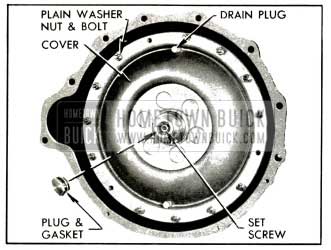
1953 Buick Converter Pump Cover
- Remove all nuts, plain washers, and bolts attaching cover to converter pump. A punch inserted through bell housing hand hole into a drive bolt hole will hold pump from turning.
- Remove cover from pump, tapping or prying against the edge to loosen it. Check the cover seal for damage or evidence of oil leakage before removing it from cover.
- Insert screwdriver into a hole in the first turbine disk to aid in removing the twin turbine assembly from the input shaft. Push inward on shaft to avoid withdrawing it. Remove bronze thrust washer from turbine hub. See figure 4-12.
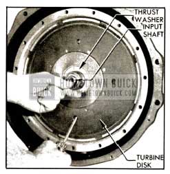
1953 Buick Removing Twin Turbine Assembly
- Remove retaining ring from groove in input shaft, using snap ring pliers, then remove bronze thrust washer and the sun gear. See figure 4-13.
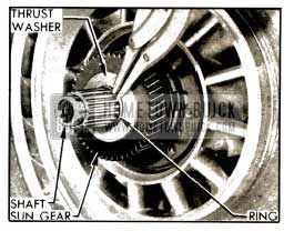
1953 Buick Retaining Ring, Washer and Sun Gear
- Remove retaining ring from groove in reaction shaft and slide the converter stator and free wheel roller race from reaction shaft. See figure 4-14.
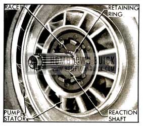
1953 Buick Converter Stator Mounting
Remove stator bearing from reaction shaft if it did not come out with the stator.
- Pull the converter pump forward from the reaction shaft (fig. 4-15) and immediately check for evidence of oil leakage.
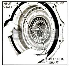
1953 Buick Removing Converter Pump
Radial streaks of fresh oil on back of pump and fresh oil streaks on face of front oil pump body indicate leakage past the oil pump seal.
Disassembly of 1953 Buick Torque Converter Units
- Pry retaining ring out of groove in first turbine, insert screwdriver in a hole in the disk and lift disk and hub assembly out of first turbine. See figure 4-16.
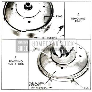
1953 Buick Removing Disk and Hub Assembly
- Lift the second turbine and carrier assembly out of first turbine.
- Remove four bolts with lockwashers and the pinion pin lock plate from second turbine. See figure 4-17. It is not necessary to remove the turbine from carrier at this time.
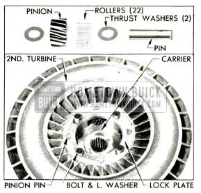
1953 Buick Second Turbine Parts
- Remove pins, then remove the four planet pinions and thrust washers from turbine carrier. Remove bearing rollers (22) from each pinion. See figure 4-17.
- Remove ball bearing from rear side of converter stator, push the free wheel roller race out of the free wheel cam in front side of stator, then remove all rollers, cups, and springs from the cam. See figure 4-18.
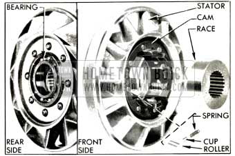
1953 Buick Stator and Free Wheel Parts
- Pry the pilot bearing retaining ring out of its groove in hub of converter pump cover, then push the pilot bearing and bearing retainer out of the hub. See figure 4-19.
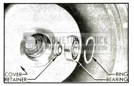
1953 Buick Pilot Bearing and Retainers
Inspection of 1953 Buick Torque Converter Parts
- Clean and inspect ball bearings as described in Section 1-B of 1952 Buick Shop Manual. Wash all other parts in clean solvent and dry thoroughly.
- Inspect all planetary gear teeth, thrust washers, bushings, and related bearing surfaces for excessive wear, scoring or other damage.
- Inspect free wheel roller springs for distortion and check rollers and race for nicks or burrs. Small nicks or burrs should be removed with an Arkansas stone and polished with crocus cloth.
- Inspect converter pump, turbines and stator for damaged or cracked vanes.
- Inspect rear edge of first turbine hub (at ring gear) and the mating thrust surface on second turbine (around carrier) for wear, scoring or other damage. Inspect turbine carrier for excessive wear or other damage.
- If second turbine or the carrier must be replaced, use care in separating them to avoid damage to the good part.
- With second turbine suitably supported, tap carrier free of counterbore in turbine, using hammer and a hardwood dowel or other soft punch. Do not drive against surface of thrust boss in carrier. See figure 4-20.
1953 Buick Removing Carrier from Turbine
- lnspect converter pump hub for scores and for wear caused by the front pump seal. If pump is suspected of leaking oil it may be tested as described in subparagraph c.
- Replace all worn or damaged parts.
Testing Converter Pump for Oil Leakage
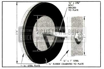
- Prepare a plate with rubber washer to close the opening in converter pump hub, as shown in figure 4-21.
1953 Buick Plate and Washer for Pump Test
The bolt head should be brazed to the plate to seal the bolt hole, and the 1/8″ thick rubber washer should be cemented to the plate.
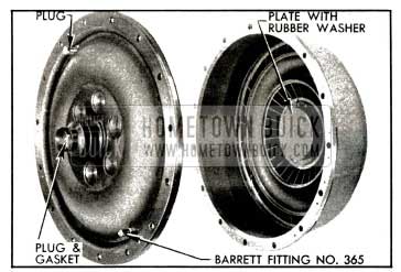
- Install plate with washer over inside surface of pump hub (fig. 4-22), then install pump cover with seal and tighten all bolts to 25-30 ft. lbs. torque in sequence shown in figure 4-34.
- Install large plug with gasket in hub of pump cover, install one drain plug, and install a Barrett fitting No. 365 in other drain hole. Tighten all parts securely. See figure 4-22.
1953 Buick Plate and Plugs Installed in Pump and Cover
- Attach air hose to Barrett fitting, fill pump with compressed air at 80 to 100 lbs./sq. in. and submerge pump in water tank. Air bubbles will appear at any point where oil leakage exists.
CAUTION: After a pump cover seal is used in this test it should not be used when rebuilding transmission.
4-6 ALIGNMENT OF CONVERTER PUMP AND BELL HOUSING
Converter oil leaks, front oil pump body leaks, front oil pump noise, and excessive wear of front oil pump bushing and oil seal may be caused by: (1) Excessive run-out of flywheel face (2) Excessive run-out of converter pump hub (3) Misalignment of bell housing.
When any of these conditions are encountered and there is any doubt as to their true cause, check the flywheel, converter pump and bell housing as follows:
- Check run-out of flywheel face as described in paragraph 2-26 (b) and make required corrections before proceeding further.
- Install converter pump and cover on flywheel and tighten mounting bolts to 25-30 ft. lbs. torque. Install bell housing on crankcase.
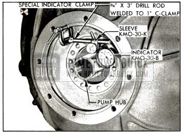
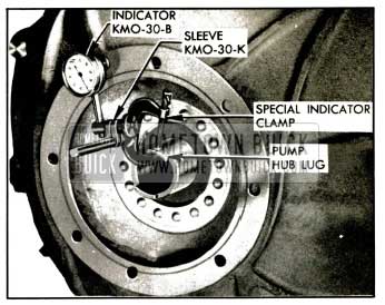
- Prepare a special dial indicator clamp by welding a piece of 5/16″ x 3″ drill rod to a 1″ C-clamp. Use the special clamp and Sleeve KM0-30-K to mount Dial Indicator KM0-30-B so that indicator stem bears against the pump hub as shown in figure 4-23.
1953 Buick Checking Run-Out of Converter Pump Hub
- Turn flywheel and note indicator reading. Run-out of pump hub should not exceed .012″. If run-out is .012″ or less, mark flywheel and pump with daub of paint so that final installation can be made in same position.
- If hub run-out exceeds .012″ mark flywheel and pump, remove pump and reinstall 180 degrees from first position, then check run-out again. If run-out is then .012″ or less, mark flywheel and pump with daub of paint.
- If pump hub run-out still exceeds .012″ after Steps 4 and 5, replace primary pump and check for run-out again.
- Attach the special dial indicator clamp to the oil pump driving lug on rear end of converter pump hub. CAUTION: Do not clamp to bearing surface of hub. Mount Dial Indicator KM0-30-B to bear against rear face of bell housing at a radius of 3 3/4″. See figure 4-24.
1953 Buick Checking Run-Out of Rear Face of Bell Housing
- Turn flywheel, making sure that crankshaft end thrust is held in one direction, and note run-out of bell housing face as shown by dial indicator. Run-out should not exceed .005″.
- If run-out of bell housing face exceeds .005″, cement paper shims of proper thickness to rear face of crankcase to bring run-out of housing face to .005″ or less, with all bolts securely tightened.
- Mount dial indicator and Hole Attachment KM0-30-F to bear against inner edge of pilot hole in bell housing. See figure 4-25. Runout of pilot hole should not exceed .004″.
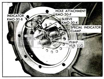
1953 Buick Checking Run-Out of Bell Housing Pilot Hole
- If run-out of pilot hole exceeds .004″, remove bell housing, remove the two dowels, and reinstall bell housing, leaving bolts just loose enough to permit shifting housing by tapping with a lead hammer.
- Set up dial indicator as shown in figure 4-25 and bring pilot hole of bell housing within .004″ run-out by tapping in required direction with lead hammer. If it is not possible to move housing far enough, remove housing and drill bolt holes with 1/2″ drill.
- When bell housing is placed so that pilot hole run-out is .004″ or less, tighten all bolts, then ream the two dowel holes through housing and crankcase, using 17/32″ Reamer J 2548-3 and Ratchet J 808-6.
- Remove bell housing and install oversize dowels J 808-5 in crankcase.
4-7 ASSEMBLY AND INSTALLATION OF TORQUE CONVERTER
Assembly of 1953 Buick Torque Converter Units
- Place the input shaft pilot bearing retainer in the hub of converter pump cover with the shouldered side upward, push the pilot bearing into hub of cover until the outer race bears against the shoulder in hub, then install retaining ring. See figure 4-19.
- If the stator was replaced, make certain that new stator has correct number of vanes-12 vanes for Series 40 or 20 vanes for Series 50-70. See figure 4-4.
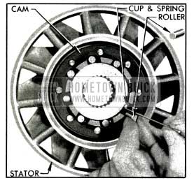
1953 Buick Installing Free Wheel Roller
- Install springs and cups and free wheel roller race in the cam on front side of converter stator, then use a suitable thin blade to depress the cup and spring while inserting each of the free wheel rollers. See figure 4-26 and 4-18.
- Install the ball bearing in rear side of stator, using care to start it squarely into place.
The bearing must be fully seated in the counterbored recess and the outer race must be free to turn. See figure 4-18.
- If second turbine was separated from the carrier, make certain that counterbored recess in turbine and mating surfaces of carrier are clean and free of burrs, and apply a film of oil to these surfaces.
- Support the carrier on suitable blocks, install several pinion pins to serve as pilots, then place turbine in position so that carrier is squarely started into recess in turbine.
- Use a hammer and hardwood dowel or other soft punch to tap the turbine down over the carrier. Avoid distortion of turbine by using light blows applied midway between holes and alternated from side to side to keep parts square with each other. See figure 4-27.
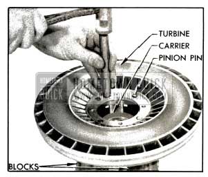
1953 Buick Installing Turbine on Carrier
NOTE: If turbine cannot be assembled on carrier with moderate force, remove it and check for burrs in counterbored recess.
- With turbine and carrier supported on wood blocks, hub side down, assemble and install the four pinions as follows:
- Place planet pinion on a thrust washer, install 22 needle bearing rollers in pinion and place a thrust washer on top of pinion. NOTE: A loading tool made locally of steel rod %” in diameter by LYJ. 6″ long will simplify loading and installation of pinion. See figure 4-28.
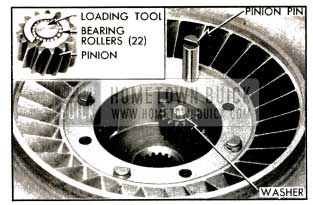
1953 Buick Installing Pinion in Carrier
- Place assembled pinion in carrier and install a pinion pin with notched end up. After loading tool is pushed out of carrier, slide a block under pinion pin to hold it in place. Turn all pins so that notches face center of carrier. See figure 4-28.
- Place planet pinion on a thrust washer, install 22 needle bearing rollers in pinion and place a thrust washer on top of pinion. NOTE: A loading tool made locally of steel rod %” in diameter by LYJ. 6″ long will simplify loading and installation of pinion. See figure 4-28.
- Install pinion pin lock plate so that it enters the notches of all pins, the install the four turbine-to-carrier bolts with lockwashers. See figure 4-17.
- Place second turbine and carrier assembly in first turbine, then install the first turbine disk and hub assembly over the second turbine. See figure 4-16, view B.
- Rotate disk until the ring gear meshes with the carrier pinions, then align driving lugs on disk with notches in first turbine and push the assembly all the way down into turbine.
- Note that the turbine disk retaining ring is “dished”. Place the ring in position with the “dish” upward so that the inner edge will bear firmly against the disk when the ring is engaged in the groove in first turbine. See figure 4-29.
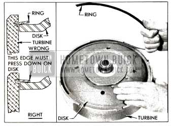
1953 Buick Installing Disk Retaining Ring
- Start one end of ring into groove in turbine, then twist the ring upward as shown in figure 4-29 to lay the ring flat on the disk so that it can be progressively entered into the groove all the way around.
- Make certain that the ring is fully seated in the groove and that inner edge bears against the turbine disk. Tap inner edge down against disk if it has raised up.
Installation of 1953 Buick Torque Converter Units
- Install the converter pump on reaction shaft, turning it until lugs on pump hub enter the slots in front oil pump driving gear. See figure 4-15.
- Make sure that the ball bearing is properly seated in the converter stator, then install this unit on the reaction shaft while pushing against the roller race to keep it from sliding out of place. Install stator retaining ring in groove in reaction shaft. See figure 4-14.
- Install sun gear on input shaft and mesh it with free wheel cam in the stator, then install the bronze thrust washer on shaft.
- Place the tapered Expander J 5338-2 on end of input shaft. Use Driver J 5338-1 to push the second turbine retaining ring over the expander and shaft until it seats in groove in shaft. See figure 4-30.
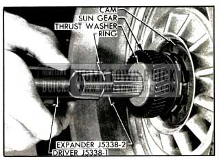
1953 Buick Installing Turbine Retaining Ring
- Support twin turbine assembly so that all weight rests on a block placed under center of second turbine.
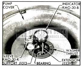
- Attach Extension J 5339 to plunger of Dial Indicator KM0-30-B, then mount indicator on Support J 1013 with Sleeve KM0-30-K. Place indicator support on the protruding hub of the turbine carrier, adjust dial indicator so that the extension bears at 90 degrees against the ground surface on first turbine hub, then set indicator at zero. See figure 4-31.
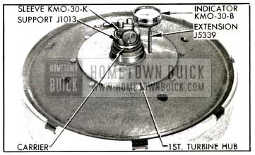
1953 Buick Dial Indicator on Turbine Assembly
- Support converter pump cover on blocks in a horizontal position, lightly tap the input shaft pilot bearing down against the shoulder in hub of cover, and place a bronze thrust washer in recess at center of pump cover.
- Remove dial indicator and support from turbine assembly and set it firmly on the thrust washer on pump cover so that the indicator plunger extension bears against inner race of pilot bearing. See figure 4-32.
1953 Buick Dial Indicator on Pump Cover
Use care to avoid changing the zero setting of dial indicator.
- The dial indicator should read between .002” and .010 clockwise from zero because the distance measured in step 8 (fig. 4-32) must be .002″ to .010″ LESS than the distance measured in step 6 (fig. 4-31). This difference is required to give the first turbine proper end play or operating clearance in its position between the pump cover and the second turbine.
If the indicator does not read within specified limits, select another washer of proper thickness. Thrust washers are available under Group 4.127 as follows:

1953 Buick Dial Indicator Thicknesses
- Install twin turbine assembly on input shaft, turning it as required to mesh the planet pinions with the sun gear.
- Looking at front face of converter pump cover, select the three bolt holes (X) that are aligned with the center of the hub and one of the counterbored recesses adjacent to hub. Mark these holes for later installation of the flywheel to-pump driving bolts. See figure 4-33.
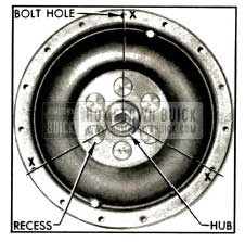
1953 Buick Location of Driving Bolt Holes
- Install a new O-ring seal on pump cover, making sure that surfaces are clean and that seal has even tension all around and is not twisted.
- Grease the selected thrust washer so it will adhere and place it in recess in cover, then install cover on pump so that the three marked driving bolt holes are not aligned with any hole in pump rim at which a balance weight is located.
- Install bolts with plain washers and special nuts in all but the three driving bolt holes, insert the shank of a 11/32″ drill through one bolt hole to align all holes, then tighten bolts to approximately 5 ft. lbs. torque in numerical sequence shown in figure 4-34. Finally tighten bolts in same sequence to 25-30 ft. lbs. torque.
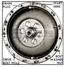
1953 Buick Bolt Tightening Sequence
When tightening bolts, insert a wide screwdriver blade between flat side of bolt head and the pump to prevent a corner of bolt from digging into pump casting.
- Screw the socket set screw with lock-washer into the input shaft through opening in pump cover hub.
- Remove reverse band adjustment cover and shift into “Parking”. Pry up on reverse band operating lever with screw driver to lock input shaft, then tighten socket set screw to 25-30 ft. lbs. torque. See figure 4-35.
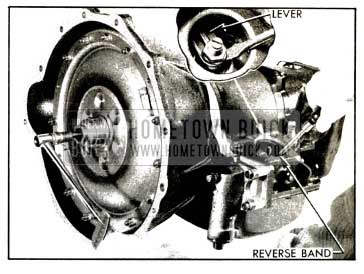
1953 Buick Tightening Set Screw
- Install large hex plug with gasket in hub of pump cover and tighten securely. Install adjustment cover and gasket.
Leave A Comment
You must be logged in to post a comment.