SECTION 3-F – 1953 BUICK CARTER 4-BARREL CARBURETOR
3-21 DESCRIPTION AND OPERATION OF 1953 BUICK CARTER 4-BARREL CARBURETOR
General Description
The Carter Model WCFB carburetor used on the Series 70 engine is a 4-barrel downdraft type which provides the advantages of a compound installation of two 2-barrel carburetors in one compact unit. See figure 3-40.
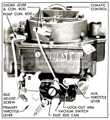
1953 Buick Carter WCFB Carburetor Assembly
To aid description and the proper identification of parts the 1953 Buick Carter 4-barrel carburetor is consider to be divided into a primary section and a secondary section.
The primary section covers the 2-barrelled forward half of the 1953 Buick Carter 4-barrel carburetor assembly. This section is essentially a complete 2-barrel carburetor containing a float system, low speed system, high speed system, power system, and accelerating system. This section also includes an accelerator vacuum switch for starting the engine, and the climatic control (automatic choke) mechanism.
The secondary section covers the 2-barrelled rearward half of the 1953 Buick Carter 4-barrel carburetor assembly. This section is essentially a supplementary 2-barrel carburetor which cuts in to assist the primary section when a pre-determined car speed or engine load is reached. This section contains a float system, low speed system with fixed jets (non-adjustable) and a high speed system. It has a separate set of throttle valves and a set of auxiliary valves which are located in the barrels above the throttle valves.
The primary throttle valves are operated by the accelerator pedal and the connecting throttle linkage. The secondary throttle valves are operated by the primary throttle valve shaft through delayed action linkage which permits a pre-determined opening of the primary valves before the secondary valves start to open. Action of the linkage then causes both sets of throttle valves to reach the wide open position at the same time.
The accelerator vacuum switch, which is operated by the primary throttle valve shaft, is fully described in paragraph 10-29. The other systems of the carburetor are described in the following subparagraphs.
Operation of Float Systems
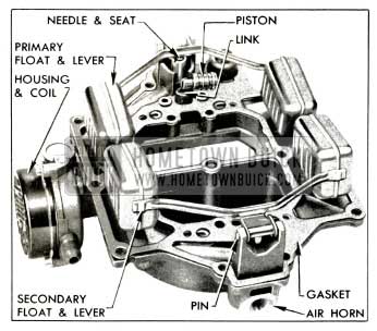
Each section of the 1953 Buick Carter 4-barrel carburetor has a separate float system consisting of a float bowl formed by a partition in the body, a 2-pontoon float and lever, needle, and needle seat. Fuel enters the carburetor through a strainer in the inlet passage above the secondary needle seat. From this point, fuel is supplied to the primary float bowl through a passage in the air horn. See figure 3-41.
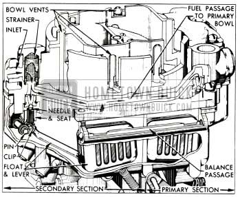
1953 Buick Primary and Secondary Float Systems WCFB Carter
When the fuel reaches the prescribed level in each float bowl the float and lever moves the needle against its seat to shut off flow of fuel. A connecting passage along one side of the body effects a balance of the fuel levels and air pressures between the primary and secondary float bowls.
The joint between the air horn and body is sealed by a gasket, and the bowls are vented by passages which are calibrated to provide proper air pressure above the bowl fuel under all operating conditions. These passages in the air horn lead into the air cleaner elbow and also to outside atmosphere.
Operation of Low Speed Systems
Each barrel of the 1953 Buick Carter 4-barrel carburetor has a separate low speed system but the general operation is identical in all barrels. The low speed system in each barrel supplies fuel to the engine whenever the position of the throttle valve is such that suction is created at the idle ports in the wall of the body flange. This happens at idle and part throttle operation.
Suction on an idle port causes fuel in float bowl to flow through the metering rod jet (primary side) or main metering jet (secondary side) into a passage which supplies both the low speed jet and the main nozzle. It then flows upward through the low speed jet which meters the fuel used by the low speed system. Above the low speed jet the fuel is combined with a stream of air coming in from the 1953 Buick Carter 4-barrel carburetor throat through a by-pass. The combining of the air stream with the fuel tends to atomize or break up the gasoline into a vapor. See figure 3-42.
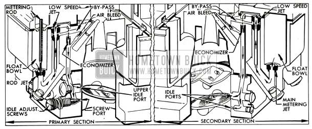
1953 Buick Primary and Secondary Low Speed Systems-WCFB Carter
The fuel-air mixture passes through a small drilled passage called the economizer and is combined with an additional air stream coming through the air bleed from the throat of the 1953 Buick Carter 4-barrel carburetor. This additional air tends to break the fuel particles into a still finer vapor.
The fuel-air mixture that flows downward through the idle mixture passage and out through the idle ports is still richer than an idle mixture needs to be, but when it mixes with the air coming in past the throttle valve, it forms a combustible mixture of the right proportions for idle speed.
The upper idle port is slotted vertically. As the throttle valve is opened it not only allows more air to come in past it but also uncovers more of the idle port, thereby allowing a greater quantity of the fuel-air mixture to enter the 1953 Buick Carter 4-barrel carburetor throat from the idle mixture passage.
With continued opening of the throttle valve the suction on the idle ports tapers off until a point is reached where the low speed system no longer supplies fuel-air mixture. Before this point is reached, however, the high speed system has begun to supply fuel, as described later.
In the primary section, the quantity of fuel-air mixture supplied through the lower idle ports is controlled by the idle adjustment screws, which may be adjusted to provide smooth engine idle operation. In the secondary section, the quantity of fuel air mixture is controlled by the size of the ports.
The secondary throttle valves remain closed during normal idle and intermediate speeds of the engine, until the primary throttle valves are opened approximately 40-45 degrees. While the secondary valves are closed, fuel-air mixture is continually delivered from the secondary lower idle ports. As the secondary valves are opened additional fuel-air mixture is supplied through the upper idle ports as previously described.
Operation of High Speed Systems
Each barrel of the 1953 Buick Carter 4-barrel carburetor has a separate high speed system which supplies fuel to the engine whenever the position of the throttle valve is such that the incoming air stream creates suction on the main nozzle. The high speed systems in all barrels operate in a similar manner except that the fuel flow through the systems in the primary section is controlled by metering rods and jets, while the fuel flow in the secondary section is controlled by main metering jets only.
In each barrel, air entering through the air horn passes through the venturi system which increases the velocity of the air and creates a suction on the main nozzle. This causes fuel in the float bowl to flow through the metering rod jet (primary) or main metering jet (secondary) into the main nozzle, from which it is discharged into the air stream passing through the small venturi. See figure 3-43.
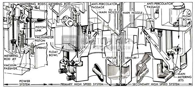
1953 Buick High Speed and Power Systems-WCFB Carter
If any vapor bubbles are formed in the hot gasoline in the main nozzle passage, they rise in the low speed jet well and the vapor exhausts through the anti-percolator passage into the barrel. This avoids percolating difficulties which might occur if the vapor bubbles rose directly into the main nozzle.
In each barrel of the primary section, the amount of fuel entering the high speed system is metered or controlled by the area of the opening between the metering rod jet and the end of the metering rod which extends into the jet. The lower end of the metering rod has steps of different diameters to provide different metering areas, depending upon the position of the metering rod in the jet. The metering rod is connected by a link, countershaft and connector rod to the primary throttle shaft so that it is raised when the throttle valve is opened and lowered when the throttle valve is closed.
On idle and part throttle operation the largest or economy step of metering rod extends into the jet, thereby giving the smallest metering area. As the throttle valve is opened for high speed or greater power, the metering rod is raised so that the middle step and later the smallest or power step provides increased metering area between rod and jet. At top speed, the smallest or power step is in the jet.
Engines operated at part throttle on level road use a mixture of maximum leanness. The mixture for greatest power and acceleration is somewhat richer, and is furnished by the power and accelerating systems described later.
The high speed systems in the primary section control the flow of fuel during the intermediate or part throttle range of operation and up to approximately 85 MPH. The secondary throttle valves remain closed until the primary valves have opened approximately 40-45 degrees, after which they are opened proportionately so that all valves reach the wide open position at the same time. While the secondary valves are closed, the auxiliary valves located above them are held closed by the weight on the auxiliary valve shaft lever (fig. 3-40); therefore there is not sufficient air flow through the barrels to operate the high speed systems in the secondary section.
When the secondary throttle valves are open and the engine speed is at least 1200-1400 RPM, the resulting air flow through the secondary barrels forces the auxiliary valves open because their supporting shaft is located off-center in the barrels. When the auxiliary valves are open the high speed systems in the secondary section also supply fuel to the engine.
Operation of the Power System
For maximum power or high speed operation above approximately 85 MPH, a richer mixture is required than that necessary for normal throttle opening. The richer mixture is supplied through the high speed systems in the primary section through vacuum control of the metering rods.
The power system consists of a vacumeter piston located in a cylinder connected to manifold vacuum, a spring which tends to push the piston upward against manifold vacuum, and a vacumeter piston link attached to the piston and supporting the two metering rods. See figure 3-43.
Under part throttle operation, manifold vacuum is sufficient to hold the piston and link down against the tension of the spring, so that the link is held against the tongue of the metering rod arm. The metering rods are then raised and lowered mechanically as the throttle valve is opened and closed. When the throttle valve is opened to a point where additional fuel is required for satisfactory operation, manifold vacuum decreases sufficiently so that the piston spring moves the piston, link and metering rods upward to the proper metering rod step position to give the required richer mixture, independently of throttle opening. As soon as the demand is passed, manifold vacuum moves the piston link down against the metering rod arm so that the metering rods are controlled mechanically again.
Operation of Accelerating System
The accelerating system supplies the extra quantity of fuel which is needed momentarily for smooth and rapid acceleration when the throttle valve is suddenly opened at speeds below 30 MPH. This system is built into the primary section of the 1953 Buick Carter 4-barrel carburetor.
A pump plunger, operating in a cylinder cast into the primary float bowl, is mechanically operated from the throttle valve shaft by means of the throttle shaft arm, pump connector rod, pump operating arm and countershaft assembly, pump arm and pump arm link. The pump circuit contains intake and discharge check valves and a discharge passage leading to a pump jet in each primary barrel of 1953 Buick Carter 4-barrel carburetor. See figure 3-44.
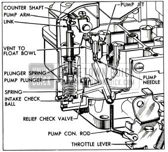
1953 Buick Accelerating System- WCFB Carter
When the throttle is closed, the pump plunger moves up and draws a supply of fuel from the primary float bowl past the intake ball into the pump cylinder. When the throttle is opened, the pump plunger on its downward stroke exerts pressure on the fuel which presses the intake ball against its seat, raises the check needle off its seat and discharges a metered quantity of fuel through the pump jets into each barrel of 1953 Buick Carter 4-barrel carburetor. The pump plunger spring provides a follow-up action so that the fuel discharge carries out over a brief period of time. A relief check valve connecting the discharge passage with the float bowl prevents excessive build-up of pressure in case the throttle is suddenly snapped open. See figure 3-44.
At speeds above approximately 30 MPH, pump discharge is not required for smooth acceleration. When the throttle valves are opened for higher speeds, the pump plunger bottoms in the cylinder so that pump discharge will not result from throttle valve movements.
During high speed operation a vacuum exists at the pump jets. To prevent withdrawal of fuel through the pump circuit, the passage to the pump jets is vented by a cross passage to the float bowl above the fuel level. This allows air instead of fuel to be drawn off the pump jets. See figure 3-44.
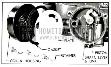
Operation of Climatic Control (Automatic Choke)
The climatic control mechanism is contained in the primary section of the 1953 Buick Carter 4-barrel carburetor. Except for minor details of construction it is identical with the same mechanism used in the 2-barrel carburetor, which is fully described in paragraph 3-16.
The secondary section does not have a choke valve in the air horn. In order to prevent air entering the 1953 Buick Carter 4-barrel carburetor through the secondary side during the engine warm-up period it is necessary to lock the auxiliary throttle valve in the closed position. This is accomplished by engagement of a lock-out arm with a locking step on the auxiliary valve shaft lever. See figure 3-40.
With the choke valve in wide open position the lock-out arm rests in a lowered position, clear of the auxiliary valve shaft lever. As the choke valve closes it rotates the fast idle cam trip lever, and an arm on the lever raises the lock-out arm. As soon as the choke valve is closed a few degrees from wide open position the hooked end of the lock-out arm lies in .the line of travel of the locking step on the valve shaft lever, thereby preventing the shaft and valves from turning.
3-22 DISASSEMBLY, CLEANING, INSPECTION OF 1953 BUICK CARTER 4-BARREL CARBURETOR
Disassembly of 1953 Buick Carter 4-barrel Carburetor
- Remove pin spring and disconnect rod from fast idle cam trip lever and choke lever. Remove choke lever from choke shaft.
- Disconnect pump connector rod from pump operating lever, push retainer off lower end of rod, and remove rod and retainer.
- Remove dust cover and gasket. Rotate eyes of metering rods off pins on vacumeter piston link and lift rods out, using care to avoid bending them. See figure 3-45.
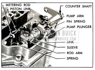
1953 Buick Metering Rod and Pump Operating Parts
1953 Buick Parts on Air Horn
1953 Buick Climatic Control Parts
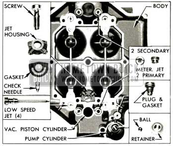
1953 Buick Parts in Main Carburetor Body
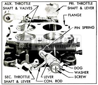
1953 Buick Throttle Parts on Body Flange
Cleaning and Inspection of Parts
The procedure for cleaning and inspection of parts is the same as the procedure for the 2-barrel carburetor. Refer to paragraph 3-19 (b, c) for carburetor parts and paragraph 3-18 (b) for climatic control parts.
3-23 ASSEMBLY AND ADJUSTMENT OF 1953 BUICK CARTER 4-BARREL CARBURETOR
During assembly of 1953 Buick Carter 4-barrel carburetor, use all new gaskets and any additional new parts found to be necessary during inspection. Calibrated parts must be as specified for carburetor CODE number.
The following new gaskets must be soaked in 90 proof denatured alcohol for 15 minutes, installed on part, and let dry before installing the parts: Needle seat gaskets; Bowl strainer nut gasket; Pump relief plug gasket.
- Drive new idle port rivet plugs firmly into openings in body flange, using Rivet Set T 109-211.
- Place secondary throttle shaft in body flange and install valves with new screws. Stamped numbers on valves must be downward and toward middle of flange. Shift the valves as required to provide the closest possible fit in barrels in closed position, then tighten screws securely. See figure 3-50. Support screw heads on suitable steel block and stake opposite ends of screws.
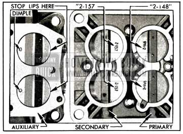
1953 Buick Installation of Carburetor Throttle Valves
Position the valve so the clearances along the sides are fairly uniform and so that the stop lips have good bearing on edge of barrels. See figure 3-50.
Tighten screws securely, support screw heads on suitable steel block and stake opposite ends.
- Slide primary throttle shaft into body flange with lever at closed throttle position.
- Install throttle valves on shaft with new screws, placing the stamped number on valves downward and toward middle of flange. Back off throttle lever adjustment screw, fully close and center both valves in barrels of body flange, then hold valves firmly while tightening screws. See figure 3-50.
- Hold body flange toward a light while slightly opening and closing valves to make certain they are centered in barrels. Support valve screw heads on suitable steel block and lightly stake opposite ends of screws.
- Install operating lever, dog, washer, and screw on primary throttle shaft, then install throttle connector rod and pin spring as shown in figure 3-49.
- Turn primary throttle valves to wide open position, with throttle lever against stop boss on body flange. The secondary throttle valves should then be in wide open position; if not, bend throttle connector rod at upper angle to obtain the wide open position, using Bending Tool T 109-41.
- Place fast idle cam and cam trip lever over fast idle screw so that tongue on trip lever is held in the notch in cam by the hooked end of cam spring, then install parts on body flange with arm of trip lever placed under the auxiliary throttle lock-out arm. See figure 3-51.
1953 Buick Fall Idle Cam and Vacuum Switch Parts
- Using Float Gauge T109-233 (3/32″ wide) for primary float or Gauge T109-222 (3/16″ wide) for secondary float, place gauge under middle of float pontoons with notched ends of gauge fitted over the edge of air horn. See figure 3-52.
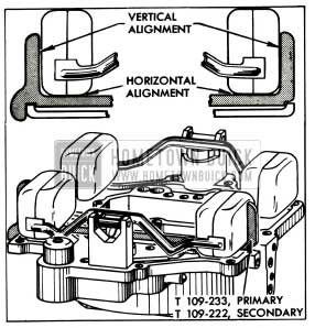
1953 Buick Checking Float Adjustment With Gauge
This distance should be 19/32″ for primary float and 11/16″ for secondary float. Adjust by bending the stop tab on float lever.
- After completing float adjustments, carefully remove float assemblies, install a new air horn gasket and reinstall float assemblies.
- Install vacumeter piston link in air horn with lip at center opening pointing toward center of horn. Use care to avoid distorting the metering rod spring or getting it out of position in link. Install piston on lower end of link.
- Carefully install air horn assembly on main body, guiding vacumeter piston into its cylinder and pump plunger rod through hole in horn. Use care to avoid straining the floats and possibly changing their adjustments.
- When installing air horn screws, place the return spring bracket at right rear corner, the cable clip just to right of fuel inlet, and the code tag at left rear corner. Beginning with the six middle screws, tighten all air horn screws gradually and uniformly to avoid warping the air horn flange.
- Connect the secondary throttle return spring between the spring bracket and the secondary throttle shaft lever.
- Install the inlet strainer, nut and gasket, and tighten nut securely.
- Coat pump operating countershaft with light graphite grease and start it into bearing in air horn. Hold pump arm in place and push countershaft through. Install spacer sleeve on countershaft. Hold metering rod arm so that it engages the opening in vacumeter piston link and push countershaft through arm.
- With pump arm pushed as far as it will go toward countershaft lever, tighten the clamp screw securely. Check countershaft for freedom from binding. Install link in pump plunger rod and outer (long stroke) hole of pump arm, with ends pointing toward countershaft arm. Install pin spring on link.
- Place pump connector rod retainer over throttle shaft lever at connector rod hole, insert end of rod through retainer and lever holes, and snap retainer into place on rod. Connect upper end of rod to pump operating countershaft arm and install pin spring on grooved end of rod.
- Adjust Accelerating Pump Plunger. Since the pump plunger travel controls the amount of fuel discharged through the pump jets, correct plunger adjustment is very important and should be checked each time the 1953 Buick Carter 4-barrel carburetor is assembled.
- Back out throttle idle stop screw until primary throttle valves seat in bores of body flange.
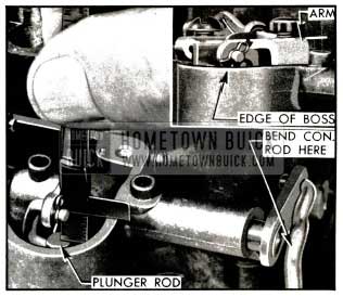
- With throttle valves held closed, measure distance that upper end of pump plunger rod is below the top edge of dust cover boss on air horn, using a narrow scale with sliding clip. See figure 3-53. This distance should be 9/32″.
1953 Buick Checking Pump Plunger Adjustment
If scale is not available, hold a narrow straight edge on top of dust cover boss. The top flat surface of pump lever should be parallel with straight edge. See figure 3-53.
- Insert end of each metering rod in hooked end of metering rod spring, carefully push rod down to enter metering rod jet, then rotate eye of rod over pin on vacumeter piston link. Use care to avoid bending metering rod. See figure 3-45.
- Adjust Metering Rods. Proper setting of the metering rods is of vital importance to engine performance and fuel economy; therefore, the following adjustments must be carefully made after adjusting the pump plunger (step 34).
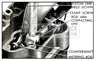
- Loosen metering arm clamp screw just enough so that arm can be turned on countershaft.
- Press down on vacumeter piston link until metering rods bottom in 1953 Buick Carter 4-barrel carburetor body casting.
- While holding rods down and primary throttle valves fully closed, revolve metering rod arm until tongue on arm contacts lip of vacumeter piston link, then carefully tighten metering rod arm clamp screw. See figure 3-54.
1953 Buick Metering Rod Adjustment
- Pack light graphite grease into holes above countershaft, then install dust cover with a new gasket.
- Install choke lever on choke shaft, connect fast idle connector rod to choke lever and fast idle cam trip lever, and install pin spring on grooved lower end of rod.
- Adjust fast idle cam and choke unloader as described in paragraph 3-17, then check adjustment of auxiliary throttle lock-out arm, as follows in step 40.
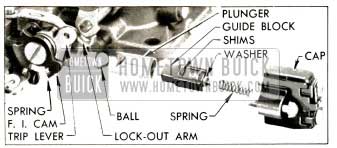
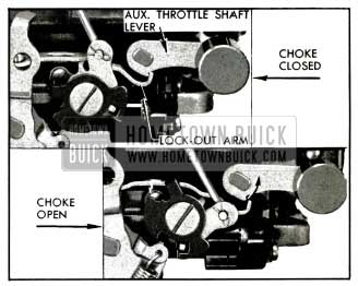
- With choke valve closed, the end of hook on lock-out arm should contact the auxiliary throttle shaft lever, making maximum engagement with locking step on lever. As choke valve is opened, the hooked end of lock-out arm should drop clear of locking step a few degrees before choke valve reaches wide open position. See figure 3-55. Bend end of lock-out arm up or down as required to meet these conditions. Check for free operation of choke valve and fast idle cam.
1953 Buick Lock-Out Arm Adjustment
Leave A Comment
You must be logged in to post a comment.