SECTION 3-A 1953 BUICK ENGINE FUEL AND EXHAUST SYSTEMS SPECIFICATIONS AND GENERAL DESCRIPTION
3-1 SPECIFICATIONS, 1953 BUICK V-8 FUEL AND EXHAUST SYSTEMS
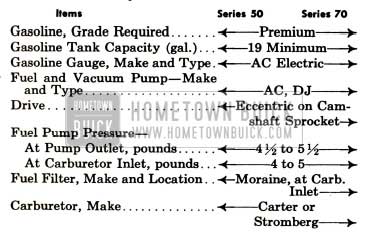
General Specifications
1953 Buick Exhaust System Specifiations
1953 Buick Exhaust System Specifiation
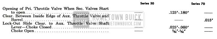
1953 Buick Carter Carburetor and Choke Calibrations
IMPORTANT: Calibrations are governed by the CODE number on the attached code tag.
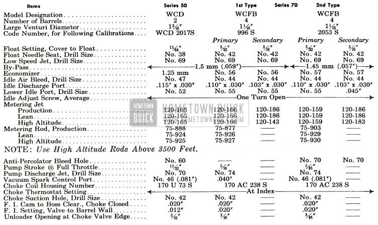
1953 Buick Carter Carburetor and Choke Calibrations Specifications
1953 Buick Stromberg Carburetor and Choke Calibrations
IMPORTANT: Calibrations are governed by the CODE number stamped on air horn directly above the fuel level sight plug.
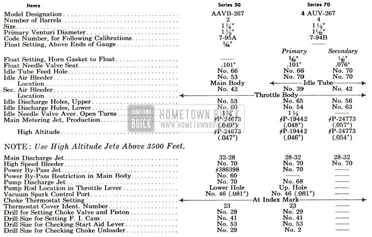
1953 Buick Stromberg Carburetor and Choke Calibrations Specifications
1953 Buick Stromberg Carburetor and Choke Calibrations Specification
3-2 DESCRIPTION OF 1953 BUICK V-8 FUEL SYSTEM
1953 Buick Gasoline Tank, Feed Pipe, and Filter
The 1953 Buick gasoline tank is attached by two strap type supports to the body under the trunk compartment, where it is seated against strips of anti-squeak material. Two internal baffles spot-welded to the upper half at centerline of tank at the support seats act as struts to maintain the shape of tank and prevent flexing due to weight of gasoline and pull of the supporting straps.
The 1953 Buick gas tank filler is soldered into its opening in the upper half of tank and the inner end is supported by the left baffle. An internal passage and a groove in the upper end of filler, where the cap seats, provide a protected air vent for the tank. See figure 3-10.
The feed pipe connects to the gasoline gauge tank unit at top of tank and is supported on the right side of car frame by clips. The front end of feed pipe is connected to the fuel pump by a rubber hose which provides the flexibility required by movement of the engine on its rubber mountings.
A Moraine gasoline filter is located at the gasoline inlet of the carburetor for the purpose of removing any dirt and water which may be present in the gasoline. The filter contains a porous bronze filtering disk and is provided with a plug for draining out the accumulated dirt and water.
1953 Buick Fuel Pump, Carburetor, and Automatic Choke
The combination fuel and vacuum pump is mounted on the right side of the timing chain cover and is actuated by a hardened, chromeplated, stamped steel eccentric mounted on front side of the camshaft sprocket. The 1953 Buick fuel section is mounted above the vacuum section, has extra-large valves, and has a built-in air dome with diaphragm to dampen out pulsations in the fuel stream. The pump construction and operation is described in Section 3-D.
1953 Buick engines of all series are equipped in production with either a Carter or a Stromberg downdraft type carburetor. Both makes are considered standard and it is not intended that these units be interchanged to provide “optional” equipment.
1953 Buick Series 50 engines use a 2-barrel carburetor and Series 70 engines use a 4-barrel carburetor. All carburetor assemblies include automatic choke mechanism and an accelerator vacuum switch. A thick fibre gasket is used between the carburetor and the intake manifold to insulate the carburetor from the heat of the manifold.
The 1953 Buick Carter carburetors are described in Section 3-E (2-barrel) and Section 3-F (4-barrel). The Stromberg carburetors are described in Section 3-G (2-barrel) and Section 3-H (4-barrel). The accelerator vacuum switches are described in Section 10-E.
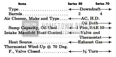
1953 Buick Air Cleaner and Intake Silencer
All series engines are equipped with heavy duty oil bath air cleaners combined with intake silencers. The 1953 Buick air cleaner removes abrasive dust and dirt from the air before it enters the engine through the carburetor. The intake silencer reduces to a very low level the roaring noise made by the air as it is drawn through the intake system. The cleaner and silencer also functions as a flame arrester in event of “backfire” through the intake system.
The 1953 Buick Series 50 air cleaner and silencer is mounted on top of the carburetor. Air enters the cleaner first and then passes through the silencer.
The 1953 Buick Series 70 inverted elbow type air cleaner and silencer is mounted lengthwise on top of the engine. Air enters the silencer first and then passes through the air cleaner located directly above the carburetor. See figure 3-1.
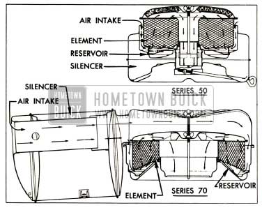
1953 Buick Air Cleaner and Silencer Assemblies-Series 50 and 70
The 1953 Buick air cleaner consists of an oil reservoir and a cleaner element containing a filtering mesh which nests down into the reservoir above the oil level. The reservoir is filled with S.A.E. 50 engine oil to a predetermined level.
Incoming air passes downward through the passage between the oil reservoir and cleaner element, impinges on the surface of the oil and turns upward into the cleaner element. The air carries oil into the element to coat the finely divided filtering mesh. The air thus exposed to a large oil wetted surface to which the dirt and impurities adhere. The cleaned air then passes through the silencer and into the carburetor. See figure 3-1.
When the throttle is closed, any excess oil on the filtering mesh drips back into the reservoir carrying the collected dirt with it. This dirt then settles to the bottom of the reservoir.
1953 Buick Carburetor Throttle Control Linkage
The 1953 Buick carburetor throttle control linkage is designed to provide positive control of the throttle valves through their entire range without being affected by movement of the engine on its rubber mountings. The linkage also serves to operate the accelerator vacuum switch when cranking the engine.
The 1953 Buick accelerator pedal is connected by two rods and a bell crank type lever to an equalizer shaft mounted horizontally on the engine to rear of the carburetor. Movement of the pedal rotates the equalizer shaft, which actuates the throttle shaft in the carburetor through a connecting rod. The throttle return spring is connect to a lever on the equalizer shaft and to a bracket anchored on the engine. See figure 3-9.
On 1953 Buicks equipped with Dynaflow Drive, a dash pot is mounted in position to be actuated by a lever on the equalizer shaft as the throttle is closed. The dash pot cushions the closing of throttle valves to prevent sudden shut off which might cause the engine to stall when the accelerator pedal is suddenly released. The dash pot is an atmospheric type in which a diaphragm and calibrated by-pass controls the closing of the throttle valves. It is sealed at assembly and is serviced as a unit only.
3-3 DESCRIPTION OF 1953 BUICK V-8 INTAKE AND EXHAUST SYSTEMS
1953 Buick Intake Manifold and Heat Control
A low-restriction, dual (2 section) intake manifold is bolted to the inner edges of both cylinder heads, where it connects with all inlet ports. The end branches of each section run at 90 degrees to the connecting middle branch, thereby forming a T-junction at the dividing point which assures a uniform division and distribution of fuel to all cylinder inlets. Each 1953 Buick manifold section feeds four cylinders-two in each bank. See figure 3-2.
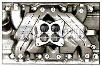
1953 Buick Intake Manifold Distribution
The 1953 Buick Series 50 2-barrel carburetor feeds one barrel into each section of its 2-port manifold. The 1953 Buick Series 70 4-barrel carburetor feeds one primary and one secondary barrel into each section of its 4-port manifold.
The 1953 Buick intake manifold is heated and hot spots are provided at the T-junction dividing points by crossover chambers cast along the outer walls of each end branch. These chambers connect to the two middle exhaust passages in each cylinder head. See figure 3-3.
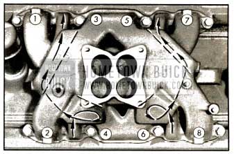
1953 Buick Intake Manifold Heat Chambers
Hot spots located at the dividing junctions aid in vaporizing the heavier particles of fuel which are swept against the outer walls due to their greater momentum. The heated intake manifold also aids in obtaining a uniform fuel distribution.
A heat control valve with a bi-metal thermostat is located in the left exhaust manifold. See figure 3-4.
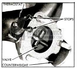
1953 Buick Manifold Valve
When the engine is cold and the thermostat closes the valve, the resulting back pressure in the manifold forces exhaust gas through the crossover chambers in intake manifold to the right exhaust manifold. As the engine warms up and the thermostat releases the valve, the flow of hot gas through the crossover chamber is reduced. Restricted openings in the metal intake manifold gaskets further reduce the flow of gases through the manifold when the engine is warm and the heat valve is open.
1953 Buick Exhaust Manifolds, Pipes, and Muffler
Each cylinder exhausts through an individual port into a separate branch of the 1953 Buick exhaust manifold, which is mounted on the outer side of each cylinder head. Use of individual exhaust ports instead of the customary “Siamese” type of porting permits valve timing that improves engine efficiency, minimizes exhaust valve burning, and effects more complete scavenging of exhaust gases from cylinders.
The left 1953 Buick exhaust manifold contains the valve which controls the supply of heat to the 1953 Buick intake manifold, as described above (subpar. a). The right 1953 Buick exhaust manifold contains an alloy steel heating tube which is connected by an insulated pipe to the automatic choke thermostat housing. The heat tube is mounted horizontally inside the manifold with the entrance end opening into a heating chamber located on the outside of manifold.
Both 1953 Buick exhaust manifolds discharge into one front exhaust pipe. This pipe crosses under the front of engine from the left manifold to meet with the right manifold in a “Y” joint that provides a common, low-restriction connection with the rear exhaust pipe attached to the muffler on right side of the frame. See figure 3-5.
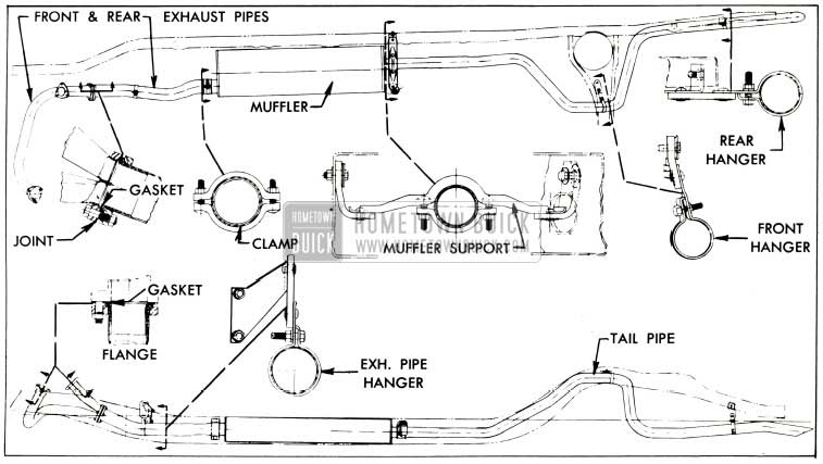
1953 Buick Exhaust Pipes, Muffler, and Mountings
The 1953 Buick muffler is an oval-shaped, dynamic flow type having very low back pressure. It is double wrapped of heavy gauge sheet steel with a layer of asbestos placed between wrappings to aid in reduction of noise transfer and prevents any “oil-canning” effect. The muffler and exhaust pipes are supported by free hanging, rubber-fabric mountings which permit free movement but eliminate transfer of noise and vibration into the passenger compartment. See figure 3-5.
Leave A Comment
You must be logged in to post a comment.