GROUP 7 – 1953 BUICK STEERING GEAR AND TIE RODS
7-1 CHANGES IN 1953 BUICK STEERING GEARS AND TIE RODS
Manual steering gears are used in Series 40-50 only. Power steering gears are optional on Series, 40-50 and are standard equipment in Series 70.
Changes in 1953 Buick Manual Steering Gears
The manual steering gears are essentially the same as described in paragraph 7-2 in the 1952 Buick Shop Manual, except for the following modifications:
The actual gear ratio has been changed to 23.6 to 1. The column jacket of the Series 50 gear fits over a tube which is pressed into the gear housing, and a clamp anchors the jacket in place. The control shaft lower bearing is pressed into the tube in gear housing and the transmission control mechanism in the 1953 Buick steering column is new, as described in paragraph 4-3.
On Series 50 Dynaflow models, a combination neutral safety and back-up light switch is mounted on the column jacket under the cowl, and is operated by a lever attached to the control shaft.
Adjustment and other service procedures given in Section 7-A of the 1952 Buick Shop Manual apply to the 1953 manual steering gears. The modifications and some dimensional changes affect interchangeability, therefore the application indicated in the Master Parts List must be observed when replacing parts.
Changes in Tie Rods
Tie rods are similar to 1952 and are serviced in the same manner as described in Section 7-A of the 1952 Buick Shop Manual. Dimensional changes affect interchangeability of some parts, therefore the Master Parts List must be observed when selecting replacement parts.
Changes in 1953 Buick Power Steering Gear and Oil Pump
The 1953 Buick power steering gear is essentially the same as described in paragraph 7-10 in the 1952 Buick Shop Manual, except for the following modifications.
New hydraulic valve having changed groove spacing, new plungers and springs, new housing with cover, and new location of the check valve in return (“RT”) port of housing. The housing and cover are piloted to insure concentricity of parts with the 1953 Buick steering shaft.
The pitman shaft is longer in Series 50-70 and length of the steering shaft is changed. The column jacket fits over the hydraulic valve cover and is anchored by a clamp. Transmission controls in the column have been changed as described in paragraph 4-3.
Only the Vickers oil pump is used in 1953. The oil reservoir is mounted on top of the pump, where it replaces the manifold previously used. A new combination overload relief valve and flow control valve replaces the separate valves previously used. Pressure and return hoses are new and not interchangeable between some models; applications indicated in the Master Parts List must be observed when replacing hoses.
Changes in the 1953 Buick steering gear and pump affect the service procedures given in the 1952 Buick Shop Manual. Complete new procedures are given in the following paragraphs.
7-2 TROUBLE DIAGNOSIS – 1953 BUICK POWER STEERING GEAR
The information given in paragraph 7-12 in the 1952 Buick Shop Manual applies also to the 1953 Buick power steering gear installation. The following condition which was not covered in the 1952 manual may be encountered in either the 1952 or 1953 models.
Failure to Recover from Turns
When the 1953 Buick steering wheel is released at completion of a turn the front wheels should return to the straight ahead position in the same manner as permitted by the manual steering gear. In cases of failure to recover from turns check the following items.
- Tightness of king pins in bushings. Lubricate or otherwise free up.
- Heavy adjustment of 1953 Buick steering gear or steering linkage (par. 7-3).
- Tight steering shaft upper bearing. Replace bearing.
- Loose worm thrust bearings; this may cause snapping noise in the gear. Remove gear assembly for proper adjustment (par. 7-4, 7-5).
- Thrust bearings reversed at assembly. Remove gear assembly and install parts correctly (par. 7-4, 7-5).
- Improper O-ring seals on each side of valve or improperly machined grooves in valve spool or valve housing. Install proper seals or replace valve assembly (par. 7-4, 7-5).
- Tip interference between center tooth of pitman shaft sector and mating tooth of ball nuts. This will be evident when lashing the gear as the scale reading approximately 120 degrees off center, left or right, will be higher than on center. This condition requires replacement of pitman shaft.
7-3 ADJUSTMENT OF 1953 BUICK POWER STEERING GEAR IN CAR
The following procedure supercedes the instructions given in paragraph 7-13 of the 1952 Buick Shop Manual.
- Disconnect pitman arm from 1953 Buick steering tie rod and check tightness of pitman arm nut with an 18″ wrench. NOTE: Never attempt to adjust steering gear with pitman arm connected to tie rod.
- Turn 1953 Buick steering wheel slowly through its full travel to check for binding, tight spots or uneven action.
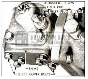
- Loosen the four corner bolts of power rack guide cover about one half turn or just enough to assure lash between the power rack and pitman shaft sector. See figure 7-1.
1953 Buick Steering Gear Adjustments
NOTE: If bolts are loosened too much, the rack will bind on sector teeth.
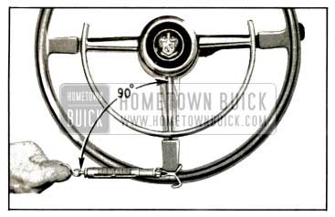
- Turn 1953 Buick steering wheel to extreme right or left position. Apply Scale J 544-A to a spoke at rim of wheel and, while pulling scale at 90 degrees to spoke, check the pull required to turn the wheel steadily in the range where lash normally exists between ball nut and pitman shaft sector. See figure 7-7. The lash range exists for one eighth turn of steering wheel from either extreme position.
- The reading on the scale should be between 3/8 and 3/4 pound, which would indicate normal loading or drag at the steering shaft upper bearing and at the thrust bearings. If within these limits proceed to step 9; otherwise continue with step 6.
- Loosen the 1953 Buick steering column bracket at instrument panel and recheck the scale pull on steering wheel in lash range. If scale reading is now within limits specified in step 5 it indicates misalignment of steering gear in its mountings at frame and instrument panel. Loosen mounting bolts at frame and shift gear assembly to provide proper alignment when all mountings are tightened.
- If scale reading is still high after releasing steering column at instrument panel, remove steering wheel, direction signal switch housing and steering shaft upper bearing.
If upper bearing is too deep or too tight .in column jacket to be removed easily, drill a hole in lower side of bearing shell and insert a self-tapping metal screw to provide a means of pulling bearing. Be very careful to avoid marring steering shaft.
- Again check the scale pull on steering wheel in lash range. A scale reading of between 1/4 and 1/2 pound indicates that the excessive loading was due to a faulty upper bearing or a bent steering shaft. If reading is not within these limits the worm thrust bearing adjustment is not correct; the steering gear must be removed from car to correct this adjustment.
- If the scale reading is within limits in any preceding step, turn steering wheel 2 3/4 turns from either extreme position to center the ball nut on the central “high point” of pitman shaft sector. At this position the center spoke of wheel should be straight down.
- Turn pitman shaft adjusting screw clockwise until lash between pitman shaft sector and ball nut is just removed, checking by working pitman arm, then tighten lock nut. See figure 7-1.
- Turn steering wheel two turns either way from central position and check pull with scale. This should be between 1/2 and one pound.
Write down the actual scale reading.
1953 Buick Checking Steering Gear With Scale
- Turn steering wheel back to near central position and check the pull required to turn wheel through the “high point” or no-lash range. Turn pitman shaft adjusting screw clockwise as required to obtain a scale reading 1/2 to 3/4 pound higher than was obtained in step 11, after lock nut is tightened. It is always advisable to adjust to near the high limit.
Write down the actual scale reading.
- Tighten the four power rack guide cover bolts and recheck the pull through the “high point”. The scale reading should be l1/8 to 1/4 pound higher than in step 12, or between 1 1/8 and 2 pounds.
If reading is not within these limits, add or remove cover shims (fig. 7-1) as required to obtain the specified pull through the “high point” or no lash range. Guide cover shims are available in .003″ and .005″ thicknesses so that they may be combined to produce any required total thickness. NOTE: To avoid spilling lubricant, it is advisable to remove filler plug with vent attached (fig. 7-1) and use a clean oil gun to draw out approximately 3/4 pint of lubricant from the gear housing before removing the guide cover.
- Connect steering tie rod to pitman arm, turn tie rod plug up solid, then back off two turns and install cotter pin.
- Fill gear housing to proper level with specified lubricant (par. 1-1).
7-4 REMOVAL AND INSTALLATION OF 1953 BUICK POWER STEERING GEAR
NOTE: Series 50-70 only. For Series 50-70 refer to paragraph 7-14 in the 1952 Buick Shop Manual.
Removal of 1953 Buick Steering Gear Assembly
- Place car cover over left front fender then remove the battery and battery shield.
- Disconnect the pressure and return line hoses from the hydraulic pump and immediately install shipping caps on pump fittings to retain oil in pump. Drain hoses and install shipping plugs to prevent dripping of oil.
- Disconnect and remove horn cable connector from steering column jacket.
- Disengage speedometer cable from clip on steering column and loosen the bolt in clamp which secures the column jacket to the steering gear valve cover.
- Disconnect transmission shift rod from the control shaft lower lever.
- Move front seat all the way back and cover the seat and back.
- Cover the steering column jacket with masking tape to prevent damage to the finish.
- Remove 1953 Buick steering wheel, using Puller J1566, then cover the horn contact and threaded end of shaft with masking tape.
- Remove signal switch and transmission shift control levers.
- Disconnect wires from the neutral safety switch and disconnect signal switch wires from the fuse block.
- Detach the rubber insulator retainer and pull it up about a foot on column jacket. Remove the jute column pad.
- Pull back the floor mat and remove the pedal plate attached to toe panel. Disconnect one end of cut-out tie bar and swing it to one side.
- Remove 1953 Buick steering column bracket (and any spacers) at instrument panel, then pull upward on column jacket to free it from the steering gear valve cover.
- Remove the cranking motor splash pan from car frame and the access hole cover from the rear fender skirt, which covers the gear to frame bolts.
- Remove the 1953 Buick steering gear to frame lower bolts and clamps, then loosen upper bolts enough so that gear can be tilted sideways to provide room for pitman arm puller.
- Remove nut and lockwasher, then remove pitman arm from pitman shaft, using Puller J 5504.
- With another man inside the car to guide the steering column and prevent damage to the column jacket and front seat, carefully lift the steering gear assembly up and forward out of engine compartment, leaving column jacket assembly in the body.
Installation of 1953 Buick Steering Gear Assembly
Install the 1953 Buick steering gear assembly by reversing the procedure for removal, paying attention to the following points.
- When installing column jacket assembly over steering shaft place Bearing Protector J 5159 over serrated end of shaft to avoid damage to 1953 Buick steering shaft upper bearing in jacket. See figure 7-3.
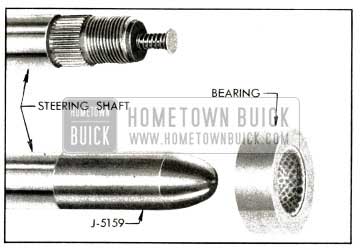
1953 Buick Steering Shaft, Bearing, and Bearing Protector
Slot in lower end of jacket must engage dowel pin in hydraulic valve cover.
- Before pitman arm is installed, mount the gear and column jacket assembly securely in clamps at frame and bracket at instrument panel, then check for bind, as follows.
- Temporarily install steering wheel and use Scale J 544-A to check the pull required to turn the wheel steadily through the high point or no lash range. The pull should not be more than 1/4, pound more than before installation, or between 1 1/8 and 2 pounds.
- If pull is greater than specified, a damaged upper bearing or a bind in the mountings is indicated. Check and correct cause of excessive loading before continuing with installation.
- Before tightening the column jacket clamp bolt, adjust the transmission control shaft lever stop plate and control linkage as described in paragraph 4-3.
- Connect the pressure line hose to the lower union on the hydraulic pump, and connect the return line hose to the upper union on pump.
- After gear installation is completed, fill the reservoir and gear housing to proper levels with specified lubricants (par. 1-1).
7-5 DISASSEMBLY, INSPECTION, ASSEMBLY OF 1953 BUICK POWER STEERING GEAR
Disassembly of 1953 Buick Steering Gear
- Thoroughly clean exterior of gear assembly with a suitable solvent.
- Remove two hoses, two large valve-to-cylinder tubes, and the small bleed line tube, then allow oil to drain from hydraulic valve and power cylinder. Remove filler plug with vent and drain lubricant from gear housing. See figure 7-4.
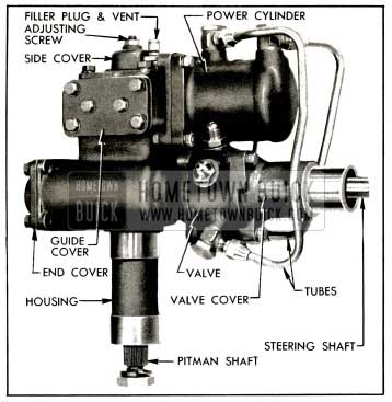
1953 Buick Left Side of Power Steering Gear Assembly
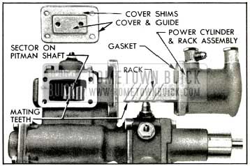
- Turn steering shaft clockwise as far as possible, remove the four corner bolts only from the power rack guide cover, then remove the cover and guide assembly and all cover shims. See figure 7-4.
- Remove bolts and elbows from power cylinder, then remove power cylinder and rack assembly, and cylinder gasket, from gear housing.
- Push rack up to the cylinder adapter and then pull it sharply away to hammer the piston against the adapter. It may be necessary to repeat this several times to break the grip of rubber seals between adapter and cylinder so that the rack and piston can be removed. See figure 7-5.
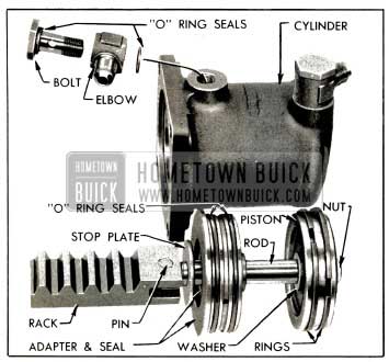
1953 Buick Power Cylinder and Rack Parts
- Remove safety nut, piston, thrust washers, adapter, and stop plate from piston rod.
- Turn 1953 Buick steering shaft counterclockwise to move the ball nut to approximate center position, then remove the gear housing side cover and gasket with pitman shaft attached by the adjusting screw. See figure 7-6.
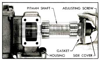
1953 Buick Removing Pitman Shaft and Side Cover
- Unscrew the adjusting screw to separate the pitman shaft from the side cover and remove adjusting screw and shim from the shaft.
- Measure from end of hydraulic valve cover to nearest edge of the horn cable contact on steering shaft and write down this dimension for use when reinstalling the contact.
- Using hot soldering iron, disconnect the horn cable from the cable contact, then remove wire and contact from steering shaft.
- Remove hydraulic valve cover. Drive up edge of worm bearing nut where staked into worm shaft keyway, using suitable chisel, then remove nut and thrust bearing. See figure 7-7.
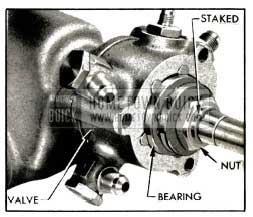
1953 Buick Thrust Bearing and Nut
- With 1953 Buick steering shaft horizontal, remove the hydraulic valve assembly, using care to keep the spool and plungers from falling out. Remove lower thrust bearing from gear housing.
- Check the valve spool and centering plungers for possible sticking in valve housing, then carefully remove these parts and the centering springs. See figure 7-8.
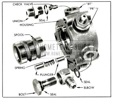
1953 Buick Hydraulic Valve Parts
Place spool and plungers where they will not be damaged by contact with other parts.
- Remove unions and elbows, then remove check valve from the return (“RT”) port of valve housing. See figure 7-8.
- Remove gear housing end cover and gasket, then remove steering shaft and ball nut from gear housing.
- Remove clamps and ball return guides from ball nut, turn nut over to remove all halls (60), then remove ball nut from steering shaft worm.
Cleaning and Inspection of 1953 Buick Power Steering Gear Parts
- Thoroughly wash all parts in clean kerosene or solvent and wipe dry with clean, lint free cloths.
- Inspect 1953 Buick steering shaft for wear or brinelling in ball and needle bearing races, which would require replacement of shaft.
- Support steering shaft in V-blocks and check it for straightness. Run-out at center should not exceed .020″.
- Inspect teeth of ball nut and all sector teeth of pitman shaft. If teeth are excessively worn or scored replace the part. Replace pitman shaft if serrated end is twisted.
- Check fit of pitman shaft adjusting screw and shim in the slot in end of pitman shaft. With shim in place, screw head must be free to turn in slot with no perceptible end play to .002″ loose. If end play is excessive, selectively fit a new shim; these are furnished in four different thicknesses.
- Inspect pitman shaft bushings in gear housing and side cover. Replace bushings in housing and replace cover assembly if bushings are worn excessively.
- Remove worm seal from gear housing with a punch and use Installer J 5189 to install a new seal with spring side outward. See figure 7-9.
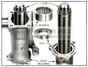
1953 Buick Installing Bearing and Seal in Gear Housing
- If worm bearing in housing requires replacement, drive it out with a punch and use Installer J 5189 to install the new bearing. See figure 7-9.
- If worm bearing in the housing end cover requires replacement, insert Remover J 5190 into bearing and turn the screw, which will expand two plates under the bearing and will then force the tool and bearing out. See figure 7-10.
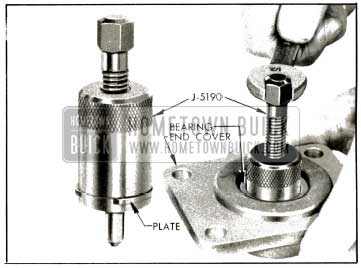
1953 Buick Removing Bearing from End Cover
Use Installer J 5191 to install the new bearing. This tool has a shoulder to locate the bearing at proper depth in cover. See figure 7-11.
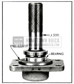
1953 Buick Installing Bearing in End Cover
- Replace pitman shaft seal, installing new seal with feather edge toward inside of gear housing.
- Inspect piston rod, teeth and guide bearing surface of power rack, and rack guide for excessive wear or scoring. If necessary to replace piston rod or rack drive out the coupling pin and use new pin to connect new parts. Stake rack at three places on each side to retain the pin, and file down burrs raised by staking.
- Inspect power cylinder bore for scores or other damage. Remove any burrs from the chamfered edge to prevent damage to seals on the adapter during assembly.
- Inspect piston rings for scores or breaks.
- Inspect piston rod seal in power cylinder adapter. If seal is damaged or of doubtful condition drive it out, and remove the O-ring seal from groove in adapter bore. Install new O-ring seal in groove, then press a new piston rod seal into adapter with the spring side inward.
- Inspect hydraulic valve housing, spool, and centering plungers for scores, nicks or burred edges. Slight stickiness of spool or plungers in housing may be corrected by polishing with crocus cloth. Do not use emery cloth. Replace damaged parts and make sure that all parts slide freely in housing.
- Test the check valve by blowing through both ends. Ball should seat when blowing through small end, and allow passage of air when blowing through slotted end of valve body.
- Remove the seal and the control shaft lower bearing from hydraulic valve cover with a punch. Press a new bearing into cover. Use Installer J 5188 to press the new seal into cover, with spring side of seal outward toward shoulder of tool. See figure 7-12.
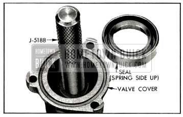
1953 Buick Installing Valve Cover Seal
- Inspect the 1953 Buick steering shaft bearing in upper end of the steering column jacket. Replace bearing if worn or damaged.
Assembly of Power Steering Gear
NOTE: Make sure that all parts are absolutely clean, and lubricate parts with clean engine oil during assembly.
- Place 1953 Buick steering shaft on bench with upper end to your right, then install ball nut on worm so that when teeth are uppermost the deeper side of teeth are toward you. Install 30 balls in each circuit of the worm, nut, and return guides, and install guide clamp.
- Run ball nut to the upper end of worm, then install steering shaft in gear housing, using care to avoid damaging worm seal in housing. Install end cover with new gasket.
- Install lower thrust bearing over steering worm with the large race outward, and place a new O-ring seal in groove in face of gear housing.
- Install check valve in “RT” port of the hydraulic valve housing and tighten securely. See figure 7-8.
- Install hose unions with new O-ring seals, placing union with smaller outer threads in valve housing port marked “PR” and other union in part marked “RT”. Install elbows and bolts at the other ports with new seals on both sides of each elbow. Do not tighten these parts.
- Place valve housing on bench with the return (“RT”) port to the right of the pressure (“PR”) port, then carefully install the valve spool with the counterbored end upward as shown in figure 7-13.
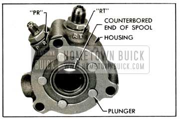
1953 Buick Spool Installed in Valve Housing
NOTE: The spool is a very close fit in housing and must be started carefully to avoid jamming. Do not force spool into place.
- Install five centering springs and ten plungers in valve housing, with drill spotted ends of plungers inward.
- With 1953 Buick steering shaft horizontal, install valve assembly with the counterbored end of valve spool outward toward the free end of steering shaft. Use care to keep spool and plungers from sliding out of housing.
- Support steering gear in a vertical position to make sure that thrust bearing balls are seated in races, then align the large (“RT”) union with left edge of cylinder flange on gear housing. Install Valve Cover Adapter J 5182 (fig. 7-14) with valve cover bolts and tighten securely.
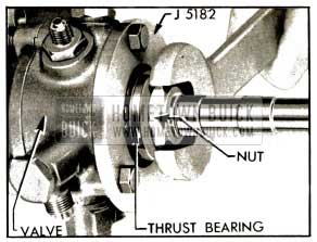
1953 Buick Tightening Worm Bearing Nut
- Install upper thrust bearing with large race toward hydraulic valve, make sure that balls are seated in races, and install a new worm bearing nut.
- Install 1953 Buick steering wheel and turn counterclockwise until centering springs are fully compressed, due to pressure of ball nut against’ the end cover. Hold wheel and tighten worm bearing nut just enough to seat the thrust bearings firmly against valve spool. See figure 7-14.
- Apply Scale J 544-A to a spoke at rim of wheel and while pulling scale at 90 degrees to spoke check the pull required to turn the wheel steadily. See figure 7-2.
- The reading on the scale should be between 1/4 and 1/2 pound. Adjust the worm nut as required to obtain this reading, then stake outer edge of worm bearing nut down into keyway of worm shaft (fig. 7-7), making sure that nut does not turn from its adjusted position.
NOTE: Check for possible looseness of bearing adjustment by attempting to turn bearing outer race by hand; a very heavy drag should exist.
- Remove 1953 Buick steering wheel and Adapter J 5182, place Protractor J 5159 over threaded end of steering shaft (fig.7-3) and install hydraulic valve cover with a new O-ring seal properly seated in its groove. With dowel pin in cover placed on opposite side from the “RT” port in valve housing install cover bolts with lockwashers and tighten securely.
- Place adjusting screw and shim in slot of pitman shaft, install side cover with a new gasket, and install lock nut finger tight on screw.
- Place gear assembly on left side, turn steering shaft until ball nut teeth are centered on pitman shaft bushings, and tilt nut slightly toward side cover opening. See figure 7-15.
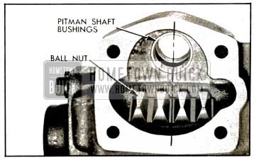
1953 Buick Position of Ball Nut for Installation of Pitman Shaft
Hold pitman shaft with the gear sectors straight down as it is installed in gear housing; use care to avoid damaging pitman shaft seal in gear housing as shaft is pushed through it. Install side cover and tighten bolts securely.
- Install 1953 Buick steering wheel and turn slowly through full range (5% turns) to check for free action, then turn wheel back to midway position (2% turns) to center the ball nut on the central “high point” of pitman shaft sector.
- Turn pitman shaft adjusting screw clockwise until lash between ball nut and pitman shaft sector is just removed and tighten lock nut.
- Turn steering wheel two turns right or left from center. Apply Scale J 544-A to a spoke at rim of wheel and, while pulling scale at 90 degrees to the spoke, check the pull required to turn the wheel steadily in the range where lash normally exists. See figure 7-2.
Write down the scale reading, which should be between 1/2 and 3/4 pound.
- Turn steering wheel back to near center and again use the scale to check the pull required to turn the wheel steadily through the “high point” or no-lash range.
- The pull through the “high point” (step 20) should be 1/2 to 3/4 pounds greater than the pull in the lash range (step 19). Turn adjusting screw as required to obtain this difference in pull after lock nut is securely tightened.
Write down the final scale reading for use later.
- Install new O-ring seals in both grooves of power cylinder adapter. Place stop plate on piston rod, then install Rod Inserter J 5193 to protect the seal as rod is pushed through seal and adapter. See figure 7-16.
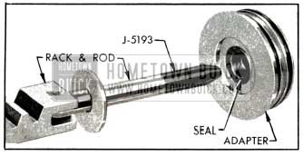
1953 Buick Application of Rod Inserter J S 193
Install thrust washer, piston with rings, thrust washer, and safety nut on piston rod and tighten securely.
- Use Ring Compressor J 5186 to compress the piston rings, then install piston and adapter in power cylinder. See figure 7-17.
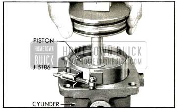
1953 Buick Installing Steering Gear Piston With Ring Compressor
It may be necessary to tap the end of power rack with a soft mallet to push rings through the compressor and into cylinder. Tap the adapter down flush with cylinder flange.
- Install the two elbows and bolts on power cylinder, place new O-ring seals on each side of each elbow. Do not tighten bolts.
- Turn steering shaft clockwise to limit of travel. Push power rack in against stop plate in cylinder adapter. Install power cylinder and rack assembly on gear housing with a new gasket. The end tooth of rack must mesh between the two end teeth in pitman shaft sector. See figure 7-18.
1953 Buick Position of Rack and Sector for Installation of Power Cylinder
- Install power rack guide and cover assembly with all of the original shims and tighten cover bolts securely.
- Use Scale J 544-A to check the pull required to turn steering wheel steadily through the “high-point” or no-lash range; this should be 1/8 to 1/4 pound greater than the pull previously obtained in step 21. Change the total thickness of cover shims as required to obtain this difference, then finally tighten cover bolts securely.
- Install the small bleed line tube and the two large valve-to-cylinder tubes. The longer tube goes on left side of gear assembly. See figure 7-4. Tighten the elbow bolts at hydraulic valve but leave elbow bolts loose at power cylinder.
- Install the horn cable contact on steering shaft with notch for cable aligned with hole in shaft and inner edge of contact located the distance from end of valve cover measured in step 9.
- Install horn cable and terminal assembly in steering shaft and solder the cable end into notch of cable contact, using soldering iron and rosin flux. Make sure that contact surface is free of flux and solder.
- Remove unions from the hydraulic valve and fill valve as completely as possible with oil specified for Dynaflow transmissions (par. 1-4), then install and tighten unions. Attach the pressure and return line hoses, fill them with oil and install plugs in open ends.
- Remove both elbow bolts from power cylinder and fill the cylinder and tubes with Dynaflow oil, then install and tighten the elbow bolts securely.
NOTE: It is desirable to fill the valve, tubes and cylinder as completely as possible to exclude air. Rapping the valve and cylinder with a soft mallet during the filling operation will aid in eliminating air pockets.
- Fill the gear housing to filler opening with Multi-Purpose Gear Lubricant specified for synchromesh transmissions (par. 1-1) and install filler plug with vent.
7-6 DISASSEMBLY, INSPECTION, ASSEMBLY OF 1953 BUICK VICKERS OIL PUMP
Disassembly of 1953 Buick Vickers Pump
- Use shipping caps to cover the hose unions on pump to exclude dirt, then thoroughly clean exterior of pump.
- Remove reservoir cover, drain out all oil then remove reservoir which is attached with four bolts on the inside. Remove two cork gaskets, being careful not to lose the spacer located in each bolt hole. See figure 7-19.
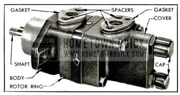
1953 Buick Steering Gear Pump with Reservoir Removed
- Remove four bolts (no lockwashers) and separate the pump cover and O-ring seal from rotor ring and body, then remove the control valve assembly and spring from pump cover. See figure 7-20.
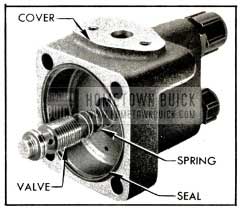
1953 Buick Pump Cover and Control Valve
- Remove the pressure plate which fits over two dowel pins extending through the rotor ring, then remove the ring, O-ring seal, and the rotor and vanes. See figure 7-21.
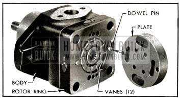
1953 Buick Pressure Plate, Ring, Rotor and Vanes
- Remove bearing retaining ring, using Ring Compressor J 5207 (fig 7-22), then press drive shaft and outer bearing out of pump body.
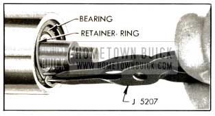
1953 Buick Removing Bearing Retaining Ring
Shaft must be pressed through the inner ball bearing which is located in body behind the shaft seal. See figure 7-23.
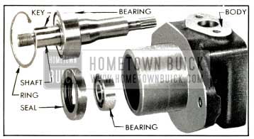
1953 Buick Drive Shalt, Bearings, and Seal
- Drive the shaft seal from body with a punch and remove the inner ball bearing.
Cleaning and Inspection of 1953 Buick Vickers Pump Parts
- Wipe the bearing and shaft assembly with clean cloths; do not soak in cleaning solvent as the lubricant sealed into the bearing may be diluted by solvent and wipe dry with clean lint free cloths.
- Inspect the drive shaft for wear and check both ball bearings for roughness or noisy operation. If the large bearing must be replaced, press the new bearing on shaft with a tool that applies pressure on the inner race only.
- Check fit of vanes in slots of rotor; vanes must slide freely but snugly in slots. Tightness may be relieved by thorough cleaning or remove] of irregularities. Replace rotor if excessive looseness exists between rotor and vanes, and replace vanes if they are irregularly worn or scored.
- Inspect all ground surfaces of the rotor ring for roughness or irregular wear. Slight irregularities may be removed with a hard Arkansas stone. Replace ring if inside cam surface is scored or worn.
- Inspect the fiat faces of the pressure plate and body for wear or scoring. These faces may be repaired by lapping until smooth and fiat, after which all lapping compounds must be thoroughly washed away.
- Inspect the control valve bore in pump cover for scores or other damage. Hair line scratches are normal but heavy scratches or scores should be cleaned up with a cylindrical hard Arkansas stone. If this cannot be done satisfactorily, replace the cover.
- First type covers had the outer end of the valve bore closed by a plug and O-ring seal. If there is leakage of oil at plug, remove ring or pin that retains the plug and push plug out of cover. Remove all burrs from around countersink and ring groove with a fine stone. Install new O-ring seal on plug, apply lubricant to seal and bore, then reinstall plug through the rear (countersink) end of bore.
- Inspect ground surfaces of the control valve for scores. Hair line scratches are normal but heavy scratches or scores should be cleaned up with a hard Arkansas stone. Replace the valve assembly if it is badly scored or if it is found to be the cause of low pump pressure. It is not practicable to disassemble, clean and assemble the valve parts and assure proper pressure control. Make certain that control valve slides freely in bore of pump cover.
Assembly of 1953 Buick Vickers Pump
Assemble the pump by reversing procedure for disassembly, paying attention to the following items:
- Make sure that all parts are absolutely clean, and lubricate all moving parts with clean engine oil during assembly.
- Use new seals and gaskets.
- Make certain that the bearings and shaft seal are firmly seated in their proper positions, After the inner ball bearing is installed, the shaft seal must be installed with the two lj11;” holes in casing toward the outside. Use a tube or shaft 1%” in diameter to apply pressure against outer edge of seal during installation.
- Install the outer bearing retaining ring with the beveled side outward.
- The rotor ring must be installed over the dowel pins with the embossed arrows pointing in a counterclockwise direction as viewed from rear end of pump. See figure 7-21. NOTE: When viewed from the front or shaft end of pump, the arrows on ring point in a clockwise direction, which is the direction of rotation of pump shaft.
- Install vanes in slots of rotor with the rounded edge outward toward the ring.
- When pump cover is installed, turn cover bolts down snug only. Install the reservoir with new gaskets, being sure that a spacer is located in each bolt hole (fig. 7-19), then tighten reservoir and pump cover bolts securely. This is necessary to assure proper alignment of the cover, reservoir, and body.
- When assembly is completed, rotate pump shaft to make sure of free movement, then install caps on hose unions to exclude dirt until pump is installed.
- When pump is installed in engine, adjust drive belt to allow 3/8″ deflection with thumb pressure midway between pulleys. See figure 2-39.
Leave A Comment
You must be logged in to post a comment.