GROUP 8 – 1953 BUICK BRAKES
NOTE: For 1953 Buick brake information not listed above refer to Group 8 of the 1952 Buick Shop Manual.
8-1 CHANGES IN 1953 BUICK BRAKE MECHANISM
The regular (foot powered) hydraulic 1953 Buick brake mechanism used as standard equipment on all 1953 models except Model 76 X (Skylark) is essentially the same as described in Section 8-A in the 1952 Buick Shop Manual. Several changes have been made which affect interchangeability of parts.
Series 50 rear brake linings are increased to 2 1/4” width, with corresponding increase in drum width. Series 70 secondary brake shoe lining is of new composition and is identified by an orange paint mark on edge of lining.
The front brake shoe geometry change which was introduced in late 1952 cars will be continued on Series 70 models. This change consisted of raising the adjusting screws 23/64” toward center of brakes and lowering the anchor pins 5/16″ toward center, thereby increasing the self-energizing action of the brake shoes and reducing effort required at brake pedal.
A very important addition to the brake mechanism is the installation of power brakes as standard equipment on Model 76 X (Skylark). The 1953 Buick power brake installation is also available as optional equipment on other Series 70 models and all Series 50; however, it is not available on the Series 40 cars.
1953 Buick brake service procedures given in Group 8 of the 1952 Buick Shop Manual apply to the 1953 standard hydraulic brake mechanism, and to the wheel brake assemblies of the power brake installations. Description and service procedures covering the power brake cylinder are given in the following paragraphs.
8-2 DESCRIPTION OF 1953 BUICK POWER BRAKE MECHANISM
General Description
Wheel brake assemblies used with 1953 Buick power brake mechanism are identical with the regular (foot powered.) brake equipment, except that a high pressure type of brake shoe lining is used. This lining is identified by its black colored edge.
The 1953 Buick power brake installation has a Kelsey Hayes Model 6 C-100 power brake cylinder in place of the master cylinder used in the regular hydraulic brake system. The brake cylinder is mounted on the car frame under the body and is connected to the brake pedal by an extended push rod. Reserve fluid is carried in a separate reservoir located under the hood, on the side and connected to the hydraulic section of the brake cylinder by a short pipe.
The 1953 Buick power brake cylinder utilizes engine manifold vacuum in its operation, as described later, therefore it is connected to the intake manifold through pipes and flexible connections. A vacuum check valve is located in this line, near the cylinder, to prevent loss of vacuum in the cylinder when the engine is stopped, or in case engine stalls.
When vacuum exists in the power brake cylinder, the force required to apply the brakes is provided by the brake cylinder instead of by foot pressure applied to the brake pedal. The driver simply applies light pressure on the pedal to control operation of the brake cylinder. Since high pedal leverage is not required, the brake pedal ratio is materially reduced so that the total pedal travel is almost half the pedal travel of the regular brake mechanism.
The 1953 Buick brake pedal pad is approximately level with the accelerator pedal when both are in released position. This convenient location combined with short pedal travel and light pedal pressure makes right foot braking extremely easy and fast because foot movement is reduced to a simple pivot action on the heel.
One or two power brake applications may be made before the vacuum in 1953 Buick brake cylinder is exhausted, after the engine stops. When vacuum does not exist in the cylinder, brakes may be applied through foot pressure on the brake pedal. It should be understood, however, that application of brakes through foot pressure alone requires relatively high effort because the power brake pedal does not provide as much leverage as the regular (foot powered) brake pedal.
Construction of 1953 Buick Power Brake Cylinder
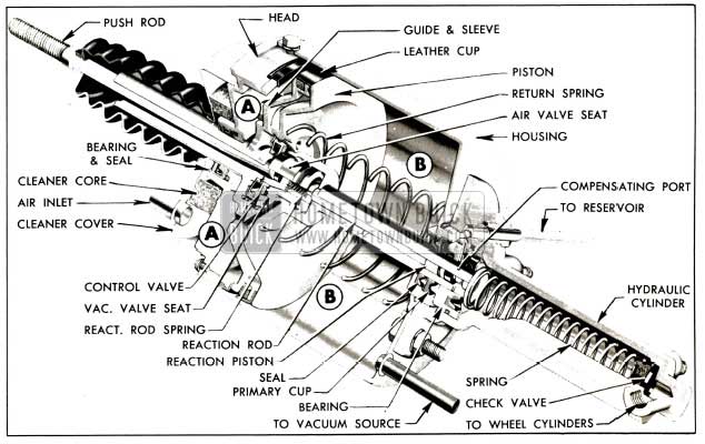
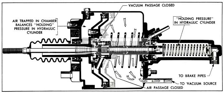
As shown in figure 8-1, the 1953 Buick power cylinder head closes the forward end of the cylinder housing to form a large air-vacuum chamber in which the power piston operates.
1953 Buick Power Brake Cylinder
The sleeve (small end) of the power piston extends through seals, cups, and a bearing in forward end if the hydraulic cylinder which is mounted on rear end of cylinder housing. The sleeve (small end) of a guide mounted on the piston extends through a bearing and seal in the cylinder head. The piston is thereby centrally supported so that it can move freely back and forth in the housing. A return spring presses the piston toward the cylinder head.
The rim of power piston carries a spring expanded leather cup to seal against passage of air, so that the piston divides the air-vacuum chamber into two separate chambers which we will call (A) air chamber (B) vacuum chamber. See figure 8-1. Engine manifold vacuum always exists in the vacuum chamber (B) when engine is running, because it is directly connected to the intake manifold by a pipe. Either vacuum or air at atmospheric pressure may exist in the air chamber (A) depending on operating stages described later; this is governed by the control valve.
The control valve parts are located in the cavity at center of the lower piston and guide assembly. The rubber diaphragm of the floating control valve is pressed over the hub of piston guide and a light coil spring presses the valve disk rearward. The air valve seat slides inside the hub of power piston, and the reaction rod spring presses it forward. In the brake released stage, the air valve seat contacts the hub of piston guide and the floating control valve disk. The cylinder push rod extends through the piston guide sleeve in position to push the air valve seat rear ward when brakes are applied. A vacuum valve seat is machined on the power piston in position to be contacted by the control valve disk. Holes in piston and guide provide air or vacuum passages to the air chamber (A). See figure 8-1.
The power piston sleeve contains a reaction piston with rubber cup and a reaction rod. See figure 8-1. Both of these parts slide freely in the sleeve and their movement is governed by the fluid pressure in the hydraulic cylinder, as explained later.
The power piston sleeve and reaction piston together form the hydraulic cylinder piston. Movement of these parts rearward into the fluid filled cylinder displaces a corresponding volume of the fluid, which is forced out into the 1953 Buick brake pipes and wheel cylinders. Compensating ports in rear end of piston sleeve permit return of surplus fluid to reservoir when brakes are released. The residual check valve and spring in the hydraulic cylinder maintains static pressure in brake pipes and wheel cylinders.
Operation of 1953 Buick Power Brake Cylinder
Description of 1953 Buick power brake cylinder operation will cover (1) Unapplied Stage (2) Applied Stage (3) Reaction Pressure (4) Poised Stage (5) Releasing Stage.
(1) Unapplied Stage. See figures 8-2 and 8-3.
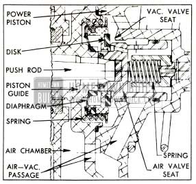
1953 Buick Control Valve Parts
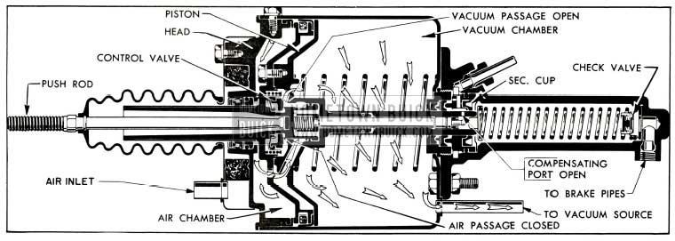
1953 Buick Unapplied Stage
The pedal return spring holds the push rod clear of the air valve seat. The reaction rod spring presses air valve seat forward against the hub of piston guide and against the floating control valve disk, thereby closing the air passages leading to the air chamber.
The air valve seat holds the floating control valve disk clear of the vacuum valve seat on power piston, thereby opening the passage through the piston and guide between the air and vacuum chambers. Manifold vacuum exists on both sides of power piston therefore pressures are equal on both sides, and the return spring holds the piston forward against the cylinder head.
The compensating ports in rear end of power piston sleeve are forward of the secondary cup, permitting flow of fluid between the reservoir hydraulic cylinder as required. The residual check valve is seated to maintain static pressure in the brake pipes and wheel cylinders.
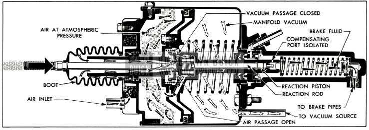
(2) Applied Stage. See figure 8-4.
1953 Buick Applied Stage
Pressure on the 1953 Buick brake pedal moves the push rod rearward into contact with the air valve seat. As the valve seat is moved clear of the piston guide hub a restricted amount of outside air starts moving through this opening, and into the air chamber. The outside air at atmospheric pressure enters through the inlet in air cleaner cover, is filtered as it passes through the felt cleaner core, then flows through the push rod boot and piston guide sleeve to the air valve opening mentioned.
Further movement of push rod and valve seat permits the floating control valve disk to bear against the vacuum valve seat on power piston, closing the vacuum passage, and then the air valve seat moves clear of the control valve disk to permit a large volume of air to enter the air chamber.
With atmospheric pressure on the head side of power piston and vacuum on the other side, the difference in pressure moves the piston rearward, forcing the piston sleeve into the hydraulic cylinder. Escape of fluid into the reservoir is cut off when the compensating ports pass through the secondary cup and the displaced fluid is forced out into the brake pipes and wheel cylinders to apply the brake shoes.
(3) Reaction Pressure. As pressure is built up in the brake pipes and wheel cylinders during brake application, the reaction piston is subjected to the same hydraulic pressure. Since the piston and reaction rod are free to move in the piston sleeve, the pressure is transmitted through the rod to the air valve seat, then through the seat and push rod to the brake pedal.
The pressure thus transmitted to the brake pedal opposes the foot pressure applied by the driver. This reaction pressure gives the driver a definite indication or “feel” of the pressure being applied to the brake shoes so that he has positive control over the braking operation at all stages.
(4) Poised Stage. See figure 8-5.
1953 Buick Poised Stage
Brake apply action and build-up of hydraulic pressure continues only as long as the pedal is kept moving to keep the push rod in contact with the air valve seat. When the push rod stops, the air valve seat stops because it is held against the push rod by the reaction rod spring. The piston continues rearward momentarily until the control valve disk contacts the air valve seat and closes the air passage.
The piston stops moving when atmospheric pressure is cut off. Since the control valve disk still bears against the vacuum valve seat on piston, air cannot be exhausted out of the air chamber, therefore the power piston remains stationary or poised, ready to move in either direction. If the 1953 Buick brake pedal is depressed for heavier brake application the air valve seat will move rearward and open the air passage. If pedal is released, the following release action will occur.
(5) Releasing Stage. When foot pressure on brake pedal is released, the pedal return spring pulls the push rod away from the air valve seat. The reaction rod spring pushes the valve seat forward into contact with the control valve disk and the piston guide hub, cutting off all air passages. The valve seat also pushes the control valve disk clear of the vacuum valve seat, opening the vacuum passage so that all air in the air chamber is immediately exhausted through the vacuum chamber. The piston return spring immediately pushes the piston forward to the cylinder head.
When the compensating ports in the power piston sleeve pass forward through the secondary cup, any surplus fluid in the hydraulic system can return to the reservoir. The residual check valve spring presses the residual check valve against its seat with sufficient pressure to maintain some residual pressure in the brake pipes and wheel cylinders.
8-3 1953 BUICK POWER BRAKE TROUBLE DIAGNOSIS
Refer to Section 8-B in the 1952 Buick Shop Manual for test and diagnosis of brake troubles related to items other than the power brake cylinder and its linkage. The following conditions relate specifically to the 1953 Buick power brake installation.
Springy, Spongy Action of 1953 Buick Brake Pedal
- Air in Hydraulic System. Thoroughly bleed entire hydraulic system (par. 8-4) after finding and correcting the leak.
Excessive 1953 Buick Brake Pedal Travel
- Improperly Adjusted Push Rod. Adjust push rod for specified end play (par. 8-4).
- Air in Hydraulic System. Thoroughly bleed entire hydraulic system (par. 8-4) after finding and correcting the leak.
- Improperly Adjusted Brake Shoes. Adjust brake shoes as described in paragraph 8-12 or 8-15 in 1952 Buick Shop Manual.
Hydraulic System Loses Fluid
- Loose Brake Pipe Connections. With engine running and heavy pressure applied to brake pedal, check all brake pipe connections, including reservoir-to-cylinder filler pipe.
- Worm or Damaged Power Cylinder Cups or Seals. Remove, disassemble, inspect power cylinder, paying particular attention to condition of primary cup and seal, reaction piston cup and O-ring, and the related gearing surfaces of the piston sleeve (par. 8-5).
Hard or Sticky Initial Pedal Pressure
May be accompanied by failure of pedal to return to release position when foot pressure is removed.
- Lack of Lubrication. Lubricate pedal shaft and push rod clevis at grease fittings.
- Binding of Corroded Clevis Pin. Remove push rod clevis pin and clean or replace it.
- Misalignment of Pedal Shaft With Push Rod. Loosen pedal shaft bracket bolts to permit bracket to shift to a free position, then tighten bolts securely.
- Dry Power Cylinder Piston Cup. Remove inspection screw in power cylinder head and inject 2 or 3 ounces of special Power Brake Cylinder Oil (Group 4.898). Back off all brake shoes, start engine and pump brake pedal until the piston moves freely. Readjust shoes.
NOTE: Use only the oil specified and DO NOT pour this oil into the reservoir because it will damage rubber cups in brake hydraulic system.
1953 Buick Brakes Do Not Release Properly
Refer to paragraph 8-7 in the 1952 Buick Shop Manual for causes of brake drag due to conditions other than the power brake cylinder and its control linkage.
- Binding at 1953 Buick Brake Pedal. Check for lack of lubrication or for corrosion at pedal bearing shaft and at push rod clevis pin.
- Push Rod Adjustment Too Long. Adjust push rod for specified end play (par. 8-4).
- Inspection Screw or Gasket Missing. Check inspection screw in power cylinder head for looseness or missing gasket. Install new gasket and tighten screw securely.
- Dry Power Unit Piston Cup. See subparagraph d item (4).
- Hydraulic Cylinder Not Aligned with Piston. Remove power cylinder, loosen hydraulic cylinder flange nuts, depress piston guide to full stroke and tighten nuts securely. Check for free movement of piston before installation of power cylinder.
- Plugged Compensation Ports. Remove and disassemble power cylinder, clean thoroughly (par. 8-5), also flush brake hydraulic system to remove all dirt.
- Power Unit Internal Friction. Remove, disassemble and inspect power cylinder, looking particularly for weak or broken springs and for dry rubber cups and O-ring seals. Reassemble as specified (par. 8-5).
Power Cylinder Does Not Boost
- Test for power cylinder operation as follows: With engine stopped, depress brake pedal several times to eliminate all vacuum from the system. Apply the brakes and while holding foot pressure on brake pedal, start the engine. If power cylinder is operating, the pedal will move slightly forward when vacuum power is added to the pedal pressure.
- If above test shows that power cylinder is not operating, check the following items.
- Vacuum Check Valve Stuck Closed. Remove and open check valve, clean parts with a dry cloth.
- Vacuum Pipe Bent, Broken or Obstructed. Check pipes from intake manifold to vacuum check valve and from there to power cylinder. Replace any damaged or plugged parts and make sure all connections are tight.
- Blocked Air Inlet. Check condition of breather hose attached to air cleaner cover, air cleaner core, push rod boot, and air passage inside the piston guide sleeve. Clean or replace parts as required.
When installing push rod boot make certain that large end is properly seated over flange of air cleaner cover and small end is properly seated over retaining ridge on push rod. Adjust push rod as specified in paragraph 8-4. - Jammed Air Valve Seat. If foreign material has jammed the air valve seat in power piston remove and disassemble power cylinder for inspection (par. 8-5).
- If above test shows that power cylinder is operating but not giving normal brake action, check the following items.
- Insufficient Brake Fluid in System. Fill reservoir, bleed all lines and check for leaks (par. 8-4).
- Binding at Brake Pedal. Check for lack of lubrication or for corrosion at pedal bearing on shaft and at push rod clevis pin.
- Damaged Secondary Cup. Remove and disassemble power cylinder for inspection (par. 8-5).
- Brake Lining Condition. Check for glazed, dirty, or oily brake linings. Clean or replace.
8-4 REMOVAL, INSTALLATION, ADJUSTMENT, BLEEDING OF 1953 BUICK POWER BRAKE CYLINDER
Removal, Installation of Cylinder
- Remove cranking motor splash pan.
- Disconnect return spring, remove clevis pin at front end, then remove brake pedal push rod with cylinder push rod attached.
- Disconnect the breather tube which is clamped to inlet tube on power cylinder air cleaner cover.
- Disconnect and remove the pipe and hose that connects the vacuum check valve to power cylinder.
- Disconnect the reservoir to hydraulic cylinder pipe, allow reservoir and pipe to drain. Disconnect distributor to cylinder pipe and allow to drain. Discard old fluid and cover pipe ends with tape to exclude dirt.
- Remove nuts and lockwashers attaching power cylinder to its support and remove cylinder from car.
- Install power cylinder by reversing the procedure for removal, except for installation of push rod and splash pan. Adjust brake pedal stop and push rod (subpar. b) then bleed hydraulic system (subpar. c) to complete the installation.
Adjustment of 1953 Buick Brake Pedal Stop and Push Rod
- Make certain that 1953 Buick brake pedal is properly lubricated and moves freely on its shaft, also that it does not bind on floor mat.
- Adjust brake pedal stop bolt, if necessary, so that the pedal grommet is compressed to 1/2″ height, then tighten the lock nut.
- Slightly wet the end of cylinder push rod with brake fluid before inserting it into the power piston guide sleeve, and be sure that the boot is drawn fully back over the retaining ridge on push rod. Make sure that rear end of boot is properly seated over the flange on air cleaner cover.
- Connect push rod to brake pedal with clevis pin and cotter pin, then check for free movement of pedal and push rod.
If a bind exists, loosen pedal shaft bracket bolts to permit bracket to shift to a free position, then tighten bolts securely.
- Starting with pedal against its stop, use fingertips only to gently move the push rod rearward until it contacts the air valve seat. Movement or end clearance of rod should be 1/16″. Loosen lock nut and turn the cylinder push rod as required to provide this clearance after lock nut is tightened.
When checking this adjustment use light pressure when contacting air valve seat because it will be moved if pressure exceeds two pounds. If seat is moved, an incorrect adjustment will be made and dragging 1953 Buick brakes will result. - Connect return spring to push rod and install cranking motor splash pan.
Bleeding Brake Hydraulic System
The 1953 Buick power brake hydraulic system must be filled with new G.M. or Delco Super No. 11 brake fluid (Group 4.683) and all air must be bled out after any work requiring disconnection of a hydraulic brake pipe.
The brake bleeding procedure given in paragraph 8-9 in the 1952 Buick Shop Manual should be used with a pressure tank attached to the reservoir. Two additional bleeder points are provided by bleeder screws located in the hydraulic cylinder.
Bleed first at the rear end bleeder screw on hydraulic cylinder, then at the front bleeder screw at cylinder flange, and finally bleed the four wheel cylinders in sequence of left front, right front, left rear, right rear.
When brake fluid runs free of air bubbles at all bleed points, start the engine and while holding pressure on brake pedal, bleed again at both hydraulic cylinder bleeder screws. Be sure to close bleeder screws before brake pedal strikes floor mat.
After bleeding is completed, make sure that reservoir is filled to proper level and check brake system for fluid leaks while applying heavy pressure on 1953 Buick brake pedal, with engine running.
8-5 DISASSEMBLY, INSPECTION, ASSEMBLY OF 1953 BUICK POWER BRAKE CYLINDER
Disassembly of Cylinder Head, Piston and Guide
- Remove push rod boot and pull out the push rod.
- Mount power cylinder in bench vise with hydraulic cylinder down. Tighten vise only enough to hold cylinder firmly; excessive tightening will crack or distort the cylinder.
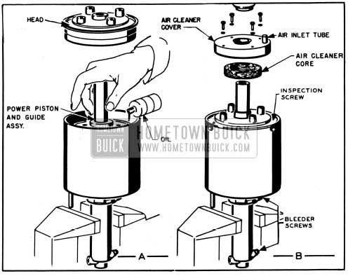
- Remove four bolts with lockwashers, pry air cleaner up with screwdriver, and remove cover and air cleaner core. See figure 8-6.
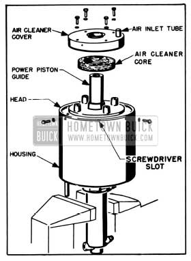
1953 Buick Removal of Air Cleaner and Cylinder Head
CAUTION: Hold down on piston guide as head is freed, to prevent the piston return spring from throwing parts upward out of control.
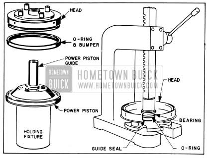
1953 Buick Removal and Disassembly of Head
1953 Buick Disassembly of Piston and Guide
Disassembly of Hydraulic Cylinder
- Remove four nuts and lockwashers which attach the hydraulic cylinder to the housing, lift off cylinder assembly, and remove the cylinder-to-housing O-ring. See figure 8-9.
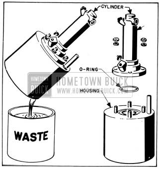
1953 Buick Removal of Hydraulic Cylinder
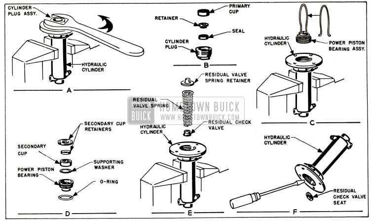
1953 Buick Disassembly of Hydraulic Cylinder
Cleaning, Inspection, Replacement of Parts
As an aid in determining the cause of improper power brake operation, wipe fluid from all rubber parts, the residual check valve, the floating control valve and air valve seat, then carefully examine these parts for nicks, cuts or other damage. After examination discard all these parts.
Thoroughly clean the remaining parts in diacetone alcohol or clean brake fluid.
CAUTION: Do not use anti-freeze alcohol, gasoline, kerosene, or any other cleaning fluid that might contain even at race of mineral oil, as this could cause serious damage to all rubber parts in the 1953 Buick brake system.
Carefully examine the cleaned parts for nicks, burrs, stripped threads, or other damage. Make certain that the small compensating ports in end of power piston sleeve are clear.
If these holes are plugged, clean them thoroughly and flush the hydraulic system to remove all dirt.
If the power piston guide sleeve, outer surface of piston sleeve, or inner surface of sleeve where reaction piston operates show evidence of abrasion, polish out light scores with crocus cloth or very fine polishing paper, then wash and dry thoroughly.
If any parts indicate that heavy abrasive action has resulted from severe contamination of the brake fluid, replace damaged parts and be sure to thor9ughly flush the reservoir and wheel cylinder lines.
The 1953 Buick Power Brake Cylinder Overhaul Kit (Group 4.898) contains all necessary replacement parts for the power brake cylinder. When reassembling the brake cylinder use all the new parts in the kit regardless of whether the old parts appear fit for use. In addition, replace any other parts which inspection indicates to be unfit for use.
Before installation, wet all O-rings and rubber cups with clean brake fluid, except where O-ring or seal is pre-greased. Do not destroy this application of silicone grease.
Conversion of Series No. 1 Power Brake Cylinder
When a Series No. 1 power brake cylinder is serviced it-is to be converted to a Series No. 2 unit by use of all parts in the overhaul kit and also replacement of the first type power piston and push rod. As noted in subparagraph a, step 12, the control spring and dampener spring used in Series No.1) is to be discarded as these parts are not used in Series No. 2.
When a Series No. 1 power cylinder is converted to Series No. 2, be sure to stamp or paint (red or yellew) the letter “K” on the cylinder head, preceding the date already stamped there.
Assembly of Hydraulic Cylinder
- Mount hydraulic cylinder in vise with flange end up, and drop a new residual check valve seat into lower end of cylinder. Dropping the seat over a drift pin will guide it into proper position. See figure 8-11, view A.

1953 Buick Assembly of Hydraulic Cylinder
Assembly of Power Piston, Guide, and Head
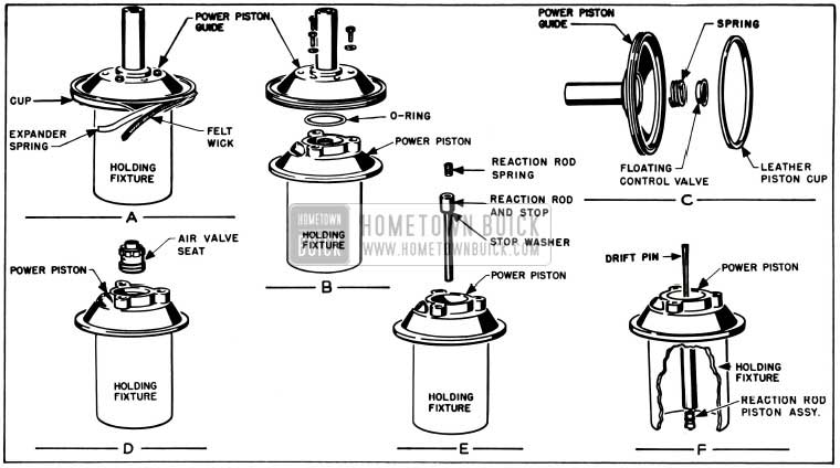
- Place expander spring in groove of power piston guide with bent ends in, so that approximate center of spring is at one of the slots in upper flange of guide, then insert wedge (supplied in kit) through slot to hold spring in place. See figure 8-12, view A.

1953 Buick Guide and Piston Parts

1953 Buick Assembly of Piston and Guide
Test action of air valve seat against spring with thumb pressure, to insure free movement.
- Place piston guide over the piston and insert the push rod through guide to hold the air valve seat down against reaction rod spring while starting bolts with lockwashers. Use three equally spaced holes in guide; the other three holes are air passages. See figure 8-13, view B.
After starting one bolt, remove the expander spring wedge, then install other bolts and tighten all securely, using care not to strip threads in aluminum piston. Remove service ring.
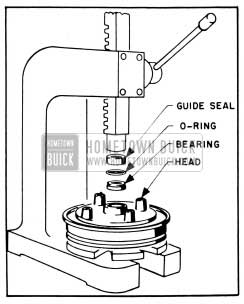
- With cylinder head resting on bench, hub end up, install bearing with flat side down and press a new O-ring into bearing groove with finger.
- Install new greased guide seal with felt side up, using care to preserve grease on seal. Using arbor press, apply only enough load to outside edge of seal to press it snugly against the bearing. Do not crush seal. See figure 8-14.
1953 Buick Installing Parts In Head
Installation of Power Piston, Guide, and Head
- Install new O-ring and bumper over outside groove of cylinder head and wet the rubber with special Power Brake Cylinder Oil supplied in parts kit. Also wipe this special oil on the inside of cylinder housing and oil the leather cup on rim of power piston guide. See figure 8-15.

1953 Buick Lubrication of Parts Before Installation
1953 Buick Installation of Piston and Head
Leave A Comment
You must be logged in to post a comment.