GROUP 13 – 1953 BUICK BODY
NOTE: For body information not listed above refer to Group 13 in the 1952 Buick Shop Manual.
13-1 1953 BUICK BODY STYLES AND NEW FEATURES
1953 Buick Body Styles
1953 Buick Body style numbers are as follows:
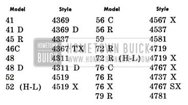
1953 Buick Body Styles
New Features
1953 Buick bodies are essentially the same as 1952 bodies; however quite a number of new features have been incorporated. Many of the new features relate to moldings, trim, paint, panel contours, etc. which affect appearance but do not require service information. The following new features are listed because they affect service procedures or interchangeability of parts.
- Hood Ledge Lacing. A new hood ledge lacing with new method of fastening is used to provide a proper seal with the alligator type hood.
- Front Door Ventilator. The new ventilator incorporates an integral type center division channel, and a drain gutter, located at the bottom of the chrome glass channel.
- Back Window Glass. A one-piece wraparound type back window glass is used on all styles except convertibles. Removal and installation is basically the same as described in paragraph 13-13 in the 1952 Buick Shop Manual.
- Instrument Panel, Front Door Finish Panels. Series 70 instrument panel and front door finish panels have a Di-Noc transfer finish. This finish is produced by flexible sheets of decorative lacquer film which are cemented to the metal panels. The Di-Noc finish may be repaired or replaced with new material by following the detailed instructions given in Fisher Body Service News No. 7. (Buick No. 1)
- Door and Quarter Trim Pads. Trim pads are redesigned on all styles. Series 70 trim pads now require a tacking operation along the top edge.
- Front Seats. Split type seats in all 2-door styles have “tilt-in” type seat backs to provide easier entrance into rear seat area of car. On Series 50-70, a diagonal movement is also provided to give greater entrance room. See paragraph 13-2.
- Rear Seats. Rear seats on Series 40 use the “zig-zag” spring construction.
- Electrical Equipment. Series 50-70 bodies have wiring harnesses and electrical units designed for 12 volts, compared with 6 volts in Series 40 bodies.
- Hydro-Lectric Power System. Model 46 C, Style 4367 X, is equipped with a new power system which operates the folding top only. This is a “sealed-in” system with a reversible motor and a spur gear type hydraulic pump. See paragraph 13-3.
13-2 1953 BUICK SERIES 50-70 FRONT SEAT SERVICE
1953 Buick Series 50-70 2-door styles use front seat assemblies having “tilt-in” seat backs and a diagonal pivoting movement of the seat cushion to provide a maximum entrance passage to the rear seat area of 1953 Buick body. When either front seat back is pushed forward it tilts inward and also acts as a lever to rotate the entire seat assembly about a pivot point on the opposite side. The seat adjusters are designed to prevent diagonal or lateral movement when the seat backs are in normal position.
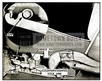
The seat adjusters are equipped with inertia locks which prevent operation of the seat in case a sudden stop should throw a seat back forward. A sudden stop causes a counterweighted lock arm to swing forward around its hinge pin until the hooked end of arm engages a lock pin, thus preventing movement of the seat assembly. See figure 13-1.
1953 Buick Inertia Lock
Checking Inertia Lock Operation
The operation of the 1953 Buick inertia lock must be checked after any service operation is performed on the 1953 Buick front seat assembly.
- Make certain that inertia lock arm operates freely on its hinge pin.
- Operate the seat backs and seat assembly to check for free operation of seat adjuster and actuating plate assemblies.
- With seat backs in full rearward position in contact with the rubber bumpers, raise the inertia lock arm into contact with the lock pin.
A gap of 1/16″ should exist between arm and pin as shown in figure 13-1. - If adjusters and actuating plates are operating properly and the 1/16″ gap does not exist in step 3, file or grind front edge of lock pin to obtain specified gap. Do not remove more than 1/16″ of stock from the lock pin.
1953 Buick Front Seat Removal and Installation
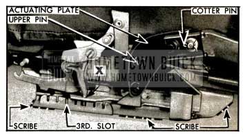
- Remove seat side panel and remove the cotter pin and cup washer from seat back outer hinge pin. See figure 13-2. Note location of rubber washer.
1953 Buick Seat Adjuster-Left Side
1953 Buick Front Seat Assembly Removal
- Remove 1953 Buick seat adjuster handle and both seat side panels.
On manual type, lock both seat adjusters in third locking slot from front. See figure 13-2.
- On hydraulic type, align the slot “X” (fig. 13-2) in both adjusters with the third locking slot.
- On hydraulic type, disconnect battery positive cable from junction block, remove regulator cover from front of seat and remove nut which attaches seat regulator to seat assembly, then disengage stud from bracket.
- Scribe the location of both seat adjusters on body floor pan (fig. 13-2) before removing the four attaching bolts from each adjuster, then remove seat assembly from 1953 Buick body.
1953 Buick Front Seat Assembly Installation
- Place the seat assembly in 1953 Buick body. With the rear end of left adjuster as far inboard as possible, align both seat adjusters with the marks previously scribed on body floor pan.
- Attach each adjuster to floor pan with four bolts.
- On hydraulic type, attach regulator to seat assembly and install cover on front of seat. Connect battery positive cable to junction block.
- Check operation of seat assembly and inertia lock (subpar. a, above).
- Install seat side panels and seat adjuster handle (manual type).
1953 Buick Front Seat Adjuster Removal
- Remove 1953 Buick front seat assembly as described in subparagraph c above, but without scribing location of adjusters on floor pan.
- Remove seat back (subpar. b, above) on same side as the seat adjuster that is to be removed.
- Rotate seat adjuster actuating plate downward far enough to disengage the upper pin from the seat adjuster cam plate slot. See figure 13-2.
- Remove rubber washer and then slide the actuating plate from the outer hinge pin.
- With seat placed bottom side up on a covered bench, remove cotter pins from both ends of the equalizing rod.
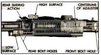
- Remove the two rearward bolts attaching the affected seat adjuster to the seat bottom frame, then remove the single attaching bolt at front end of adjuster. See figure 13-3.
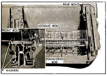
1953 Buick Seat Adjuster Attaching Parts
1953 Buick Front Seat Adjuster Installation
- Install 1953 Buick seat adjuster on seat bottom frame, making certain the following parts are properly located and attached:
- The higher surface of rear attaching bracket must be placed outboard and lower surface must be placed inboard. See figure 13-4.
1953 Buick Left Seat Adjuster-Top View
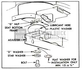
(b) The plastic washer must be placed between adjuster and seat bottom frame at front attaching bolt, with sliding surfaces well lubricated with Lubriplate, or equivalent. See figure 13-5.
1953 Buick Adjuster Front End Attachment
On Hydraulic type, set both seat adjusters in the same relative fore and aft position by aligning rear end of each seat adjuster floor bracket or stationary channel flush with the rear end of adjuster upper slide channel.
- Using the rear sliding action (on left adjuster only), move rear end of left seat adjuster inboard as far as possible.
- Visually align the front end of both seat adjusters so they are centered on the seat bottom frame front attaching bracket.
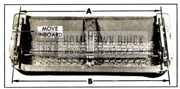
- With rear end of left adjuster all the way inboard, measure the distances “A” and “B” between centerlines of adjusters at both ends. See figure 13-6. Measurements “A” and “B” must be equal.
1953 Buick Alignment of Adjuster on Seat Bottom Frame
NOTE: Remeasure “‘A” as well as “B” after each adjustment; also make sure that rear end of left adjuster stays inboard on its sliding action.
- When measurement “A” and “B” are equal, tighten seat adjuster front attaching bolts. The extra flat washers will lock the front ends of seat adjusters to maintain measurement “B” and keep adjusters parallel while installing seat assembly in body.
- Set seat cushion and adjuster assembly in body and with rear end of left adjuster as far inboard as possible align seat adjuster and floor pan bolt holes on right and left sides. Install eight attaching bolts.
- Remove the extra flat washer that was installed in step 1 (c) and after reinstalling the front attaching bolts make sure they are free to move laterally.
- Install actuating plates and seat backs.
- On hydraulic type, attach hydraulic regulator and cover to seat assembly and connect battery positive cable to junction block.
- Check operation of the seat assembly and inertia lock (sub par. a, above), then install seat side panels and seat adjuster handle (manual type).
13-3 1953 BUICK HYDRO-LECTRIC POWER SYSTEMS
The 1953 Buick Hydro-Lectric Power System is standard equipment on Models 46 C, 56 C, 76 C, 76 R, 76 X, and is optional on Models 52 and 72 R.
The Hydro-Lectric Power System used in Series 50-70 models provides power operation of the folding top, front seat, door and rear quarter windows. The electrical units are designed for 12-volt current, otherwise the system is identical with 1952 equipment. For description and service information on this system refer to Section 13-G in the 1952 Buick Shop Manual.
The Hydro-Lectric Power System used in Model 46 C provides power operation of the folding top only. The electrical units are designed for 6-volt current and all units are of different design than relative units in the Series 50-70 system.
Model 46 C Power System Units
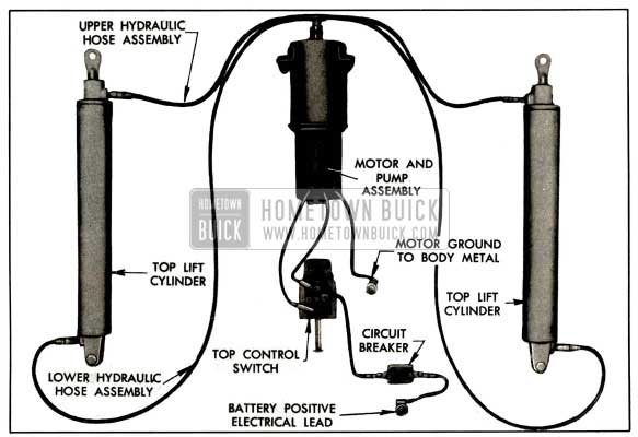
The power system used in Model 46 C is a “sealed-in” system which is not vented to atmosphere, therefore it is not necessary to replace hydraulic fluid periodically, as specified for the Series 50-70 system. All units of the “sealed-in” system are shown in figure 13-7.
1953 Buick Power System Units-Model 46C
The 1953 Buick Hydro-Lectric motor and pump assembly is mounted with rubber grommets on the right side of the rear compartment lower division panel under the folding top compartment fabric bag. The unit consists of a 6-volt reversible type electric motor, a spur gear pump and a fluid reservoir assembled vertically with the reservoir at the top.
The spur gear pump has only four moving parts-two spur gears and two ball-spring check valves. The fluid pressure developed by this pump is proportional to the speed of the motor, therefore a low battery will result in low pressure and sluggish action of the folding top. The pump must deliver fluid pressure within the range of 240 to 280 p.s.i. The motor requires 72 amperes when operating the pump at a fluid pressure of 230 p.s.i.
The motor and pump, and operation of the folding top, is controlled by means of a self centering control switch mounted on lower edge of the instrument panel to right of steering column. The switch is connected to the battery positive lead through an overload circuit breaker, and is connected to the power motor with two electrical leads. See figure 13-7.
The hydraulic pump is connected to the right and left top lift cylinders by rubber hoses equipped with 5/16″ fittings. One hose connects to the bottom end of each cylinder and one hose connects to the top end of each cylinder so that fluid pressure may be applied to either side of the piston as required. The piston and the upper end of cylinder are equipped with seals to prevent passage of fluid past the piston and piston rod.
Operation of Model 46C Power System
When the control switch knob is pushed forward to raise the folding top, electrical current from the battery passes directly through the circuit breaker and control switch to the motor. The motor and pump then operate to force hydraulic fluid under pressure through the connecting hoses to the lower ends of both top lift cylinders.
Fluid entering the lower end of each cylinder forces the piston and rod upward, and this movement is transmitted by the piston rod to the top linkage to raise the top. As the piston moves upward it forces fluid out of the upper end of the cylinder and this fluid returns to the pump through the upper connecting hose. The returning fluid recirculates through the pump. See figure 13-8.
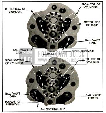
1953 Buick Flow of Fluid Through Pump
When the control switch knob is pulled rearward to lower the folding top, the motor and pump operate in the opposite direction, forcing hydraulic fluid into the upper ends of the top lift cylinders to push the pistons and rods downward. Variations in volume of fluid in cylinders, caused by piston rod displacement, is taken care of by the fluid reservoir. The ball and spring check valves in the pump permit flow of fluid between reservoir and low pressure side of pump only. See figure 13-8.
Manual Operation of 1953 Buick Model 46C Folding Top
The folding top may be raised or lowered manually if the power system is inoperative for any reason. The manual operation must be performed very slowly to avoid closing the check valve in pump through which the returning fluid must pass into the reservoir. Since the spur gears block passage of fluid between opposite ends of lift cylinders when pump is not running, the fluid must flow into the reservoir through one check valve and flow out of reservoir through the other check valve during the manual operation.
13-4 1953 BUICK POWER SYSTEM CHECKING PROCEDURES
For 1953 Buick Series 50-70, refer to paragraph 13-29 in the 1952 Buick Shop Manual. The following procedures apply only to the Model 46 C Hydro-Lectric Power System.
Mechanical Checking Procedure
Unless it is obvious that faulty operation of the folding top is caused by electrical or hydraulic faults, the first check should be of the mechanical operation of the top. Check for binding action by manually raising and lowering the top as described in paragraph 13-3 (c).
A further manual check of the top may be made by disconnecting the top lift cylinder piston rods from the folding top linkage, then rating and lowering the top by hand. The folding top should travel freely through its up and down cycle without any evidence of a binding action. Should a binding action be noted when locking the top at the header, carefully check the alignment of the door windows, ventilators and rear quarter windows in relationship to the roof side rail weatherstrips. Make all adjustments necessary for correct top alignment then proceed with the electrical and hydraulic checks.
Electrical Checking Procedure
The 1953 Buick electrical system should be completely checked before testing the hydraulic system in cases where the complete power system is inoperative.
A low battery will seriously affect operation of the power system. For efficient operation, battery specific gravity should not be less than 1.200, or equivalent voltage. Check battery condition as described in paragraph 10-15.
If battery is in satisfactory condition, carefully inspect all wires and connections at cranking motor solenoid switch, circuit breaker, top control switch, and power motor, including the ground lead. Check for loose connections, corrosion, broken wires and damaged insulation.
If source of trouble has not been found, use a good 6-volt light with one lead grounded to body and separately test all wires and units in the circuit between battery and power motor. The motor may be disconnected from the supply wiring at the “jack-knife” unions near the motor. With unions disconnected, a jumper wire of No. 8 stranded wire may be used to connect the motor directly to the battery. If motor fails to operate when directly connected to battery, the motor and pump assembly should be removed for repairs.
Hydraulic Checking Procedure
If the folding top still fails to operate, or operates in a faulty manner after the mechanical and electric checks have proved satisfactory, then the source of trouble probably lies within the hydraulic system. First make certain that the hydraulic fluid is at specified level in the reservoir (par. 13-5, b) then perform the following additional checks.
- Check Operation of Lift Cylinders. Remove the rear seat cushion, seat back and rear quarter side trim. Operate the folding top control switch to activate the motor and pump for both “up” and “down” cycles, then observe the operation of both lift cylinders. If the top in its movement appears to be sluggish or out of alignment, causing binding of the top linkage, then one of the lift cylinders is either inoperative or is operating too slow. This condition may be caused by either a defective cylinder or clogged hydraulic lines somewhere in the faulty circuit. With the system under pressure an inspection should be made of the hydraulic hoses from the “T” couplings on top of the reservoir to the top and bottom of the lift cylinder, to determine if the obstruction lies within the hoses leading to the cylinders.
- Install Pressure Gauge at Pump. Remove retainers to obtain slack in hoses connecting the pump to top lift cylinders. Remove reservoir filler plug. If top operates improperly on “up” movement, place top in raised position and install a standard pressure gauge between the pump port and “T” of hydraulic lines leading to bottom ends of top lift cylinders. See figure 13-9.
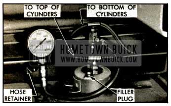
1953 Buick Pressure Gauge Installed at Pump
If top operates improperly on “down” movement, place top in fully lowered position and install the pressure gauge between pump port and “T” of hydraulic lines leading to top ends of top lift cylinders.
Reinstall reservoir filler plug and proceed with the following tests.
- Test Pressure in Hydraulic Lines. If top is up and pressure gauge is connected to the “bottom” hydraulic lines, push control switch knob forward and hold a few seconds. If top is down and pressure gauge is connected to the “top” hydraulic lines, pull control switch knob rearward and hold a few seconds.
For efficient operation of the hydraulic system the fluid pressure indicated on gauge should range between 240 and 280 p.s.i. If the pressure is below specified range, either the pump is not delivering required pressure or there is fluid leakage past the piston in one or both lift cylinders.
- Test Fluid Pressure Delivered by Pump. Pinch or kink both hoses in line to which the pressure gauge is connected in order to completely shut off fluid flow to lift cylinders, then operate the control switch as specified in step 3 above. If pressure is still below the specified range of 240-280 p.s.i. the pump is at fault. If pressure is now within the specified range, however, test lift cylinders as follows.
- Test for Leakage in Lift Cylinders. Pinch or kink the hoses leading to top and bottom of the right hand lift cylinder in order to completely shut off fluid flow, then operate the control switch as specified in step 3, above. If pressure is still below the specified range of 240-280 p.s.i., then fluid is leaking past the piston in the left hand cylinder and this cylinder must be replaced. If pressure is within specified limits, however, the left hand cylinder is satisfactory for use.
Test the right hand cylinder in the same manner while kinking hoses leading to the left hand cylinder.
13-5 1953 BUICK POWER SYSTEM SERVICE PROCEDURES
For 1953 Buick Series 50-70, refer to paragraphs 13-30 and 13-31 in the 1952 Buick Shop Manual. The f6llowing procedures apply only to the Model 46 C Hydro-Lectric Power System.
Precautions When Working on Power System
- Before disconnecting any wire or any fluid line be sure to disconnect the battery to avoid short circuits or accidental pumping of hydraulic fluid on finished surfaces or upholstery. Hydraulic fluid will damage lacquer finishes.
- Before disconnecting any fluid line always remove the filler plug on fluid reservoir, then reinstall plug before operating the system. Veinting of reservoir is necessary in this “sealed-in” system to relieve any pressure and avoid the possibility of hydraulic fluid being forced from disconnected line.
- Suitable cloths should be on hand to wipe up any spilled fluid when lines are disconnected. Hydraulic fluid is inflammable.
- When a fluid line is disconnected be sure to cover all openings to prevent entrance of dirt into the system. Also protect the ends of any wires that may be disconnected.
- When connecting “Tees” or “Elbows” in fluid lines, sparingly apply a coating of 3-M Fluid Line Sealer to the male threads, except for first thread. Connection should be firmly tightened while sealer is still wet.
- After fluid lines are connected, operate the folding top through several cycles to expel any trapped air into the fluid reservoir, then bring fluid level in reservoir to proper level. (subpar. b, below).
Maintaining Hydraulic Fluid Level
Since the “sealed-in” hydraulic system is not vented to atmosphere and exposed to contamination it is not necessary to replace the hydraulic fluid periodically. Whenever any work is done on the system the level of fluid in the reservoir should be checked and brought to proper level.
Raise the folding top, and remove the motor and pump shield in rear (trunk) compartment. Remove filler plug from fluid reservoir (fig. 13-9) and insert a suitable CLEAN dip stick. The fluid level should be 2″ below top of reservoir. Add Delco Super No. 11 Brake Fluid as required to obtain the specified level.
If fluid level is found excessively low, it is important to correct the cause of fluid loss before adding fluid to reservoir. An inspection for fluid leakage should be made if an odor of brake fluid is detected inside the body.
The fluid capacity of the hydraulic system is 3.86 pints. To refill the system, fill reservoir to specified level and operate top through several cycles, check reservoir and add fluid as required. Repeat this operation until level remains constant. One filling of reservoir may not be sufficient as the fluid capacity of the two top lift cylinders is almost double that of the reservoir.
Motor and Pump Removal and Installation
- Raise the folding top to full “up” position, then disconnect the battery.
- Remove rear seat cushion and back, also fold back the insulating pad on right side of body.
- Carefully pull wiring harness through opening in panel, remove insulation from the “jack knife” unions and disconnect the red and green wires from motor leads. Disconnect ground wire. See figure 13-10.
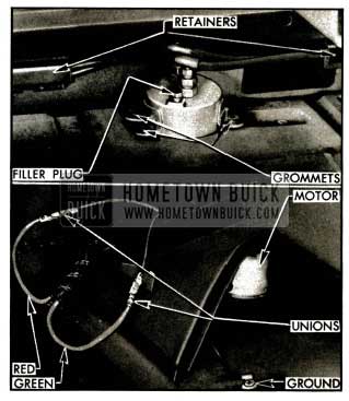
1953 Buick Motor and Pump Connections
Top Lift Cylinder Removal and Installation
- Raise the folding top to full “up” position, then disconnect the battery.
- Remove rear seat cushion and seat back, and remove the rear quarter arm rest assembly.
- Remove nut and bolt that connects lift cylinder piston rod to folding top linkage (fig. 13-11), then manually push piston rod down until piston is at bottom end of cylinder.
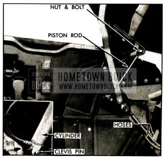
1953 Buick Lift Cylinder Connections
Leave A Comment
You must be logged in to post a comment.