GROUP 9 – 1953 BUICK FRAME
9-1. CHECKING ALIGNMENT OF 1953 BUICK FRAME
Checking Alignment of 1953 Buick Frame and Suspension Members
When a 1953 Buick frame has been damaged by accident the following procedure may be used to check alignment of the 1953 Buick frame, and the alignment of the chassis suspension members with the frame. This procedure should be used to check alignment after repairs to frame have been completed.
Checks are to be made with frame assembled with power plant, body, etc. and car resting on wheels. The car should be placed on a clean floor that is reasonably level. Both sides of the front ends of the frame must be the same distance from the floor; the same condition must exist at rear end of 1953 Buick frame. Where points are to be extended to floor by use of a plumb bob, it is desirable to attach clean pieces of paper to floor with tacks or tape so that the points can be clearly marked. Apply brakes or block wheels so that car ca mot move.
- Using a plumb bob, extend the following points to the floor and mark where point of plumb bob touches floor, as shown in figure 9-1.
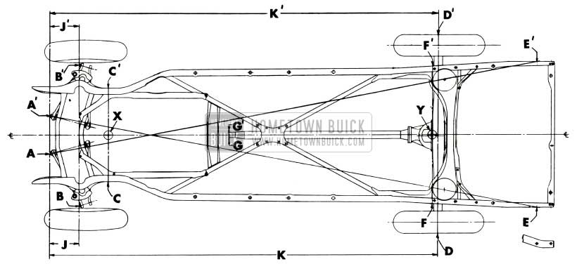
1953 Buick Checking Points for Frame and Suspension Alignment
- A and A1 at point of grease fitting in front ends of control arm shafts.
- B and B1 at point of grease fitting in front ends of lower pivot pins.
- C and C1 at jigging holes in side rails about 7″ to rear of bumper frame stops, holding plumb line flat against side rails.
- D and D1 at center of rear axle shafts.
- E and E1 at center of forward bolts attaching rear bumper.
- F and F1 on side rails just forward of rear axle rubber bumper, holding plumb line fiat against side rails.
- G and G1 at each side of torque tube flange.
- Move car out of the way. Using a chalked line, draw lines on the floor through the following points: A and A1, B and B1, C and C1, D and D1, F and F1.
- Divide the distance between C and C1 and mark the center point X on line C-C1. Divide the distance between F and F1 and mark the center point Y on line F-P. Draw frame centerline through points X and Y.
- Measure diagonal distances A to E1. If these diagonals are not equal within 3/16” the frame is bent.
- Measure the distances J and J1. If these are not equal within 1/8″ a lower control arm is bent.
- Measure the distances K and K 1, which will be equal within 3/16″ if rear axle is properly aligned with frame. Points G and G1 should be equally distant from vehicle centerline X-Y. If distances K and K1 are not equal within 3/16″ and points G and G1 are equally distant from centerline, a bent rear axle housing or torque tube is indicated. If points G and G’ are not equally distant from centerline, look for misalignment of engine in the frame.
Checking Alignment of 1953 Buick Frame Only
When a 1953 Buick frame has been damaged by accident and the power plant, body, etc., are removed, the measurements shown in figure 9-2 or 9-3 may be used to check for alignment of frame members. The procedure should also be used to check alignment after repairs to 1953 Buick frame have been completed.
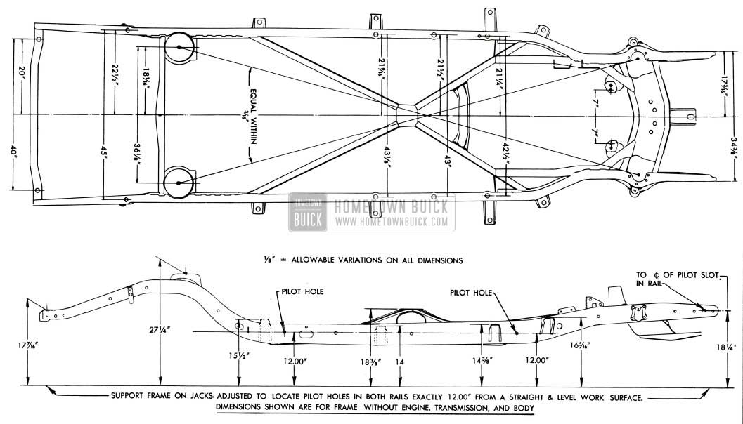
1953 Buick Frame Checking Dimensions-Series 40
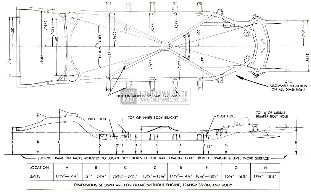
1953 Buick Frame Checking Dimensions-Series 50-70
The 1953 Buick frame must be solidly supported on suitable stands so that the top of side rails are level. Use a steel tape or adjustable trammel and a steel straight edge to obtain the measurements indicated in figure 9-2 or 9-3.
9-2. 1953 BUICK FRAME REPAIRS
Straightening and Welding
In case of frame distortion resulting from an accident it is permissible to straighten or weld the frame if the distortion is not excessive.
Heat can be applied without materially weakening the steel, provided this is kept below
1200°F. This is a deep cherry red when viewed in subdued daylight, as in an average shop. Heat in excess of 1200°F. will weaken the metal structure and lead to eventual failure in service.
Replacement of 1953 Buick Frame Members
If a 1953 Buick frame front cross member is very badly distorted as a result of a front end collision, replacement is advisable because its rigid box construction makes proper straightening very difficult. Since the front suspension members are mounted on the frame front cross member, front end alignment will be affected if the cross member is not in perfect alignment.
The front end and rear cross members, rear spring support cross member, and a number of braces and brackets are available for service replacement. The old members may be removed from the frame by cutting the attaching rivets and welds, after removing other parts or assemblies to allow working space.
When installing new frame members use hot rivets since they can be properly driven with hand tools. Cold driven rivets are not recommended because they cannot be securely driven with hand riveting tools. In places where hot rivets cannot be installed it is permissible to use finished bolts snugly fitted in reamed holes. Use lockwasher with bolts and draw nuts up tight. Weld a new member to adjacent members in the same manner that the replaced member was welded.
After installation of any new frame member check the frame for proper alignment as described in paragraph 9-1. After any repairs or replacements in front end of frame be sure to check front wheel alignment (par. 6-1, a).
Leave A Comment
You must be logged in to post a comment.