SECTION 3-D – 1953 BUICK FUEL AND VACUUM PUMP
NOTE: For Series 40 Type DG fuel and vacuum pump procedures see Section 3-D in the 1952 Buick Shop Manual.
3-11 DESCRIPTION AND OPERATION OF TYPE DJ FUEL AND VACUUM PUMP
Description of 1953 Buick Pump
An AC Type DJ combination fuel and vacuum pump for 1953 Buicks is used on all Series 50-70 engines. The pump assembly is mounted on the right side of the timing chain cover, and the pump rocker arm is actuated by an eccentric mounted on front side of the camshaft sprocket.
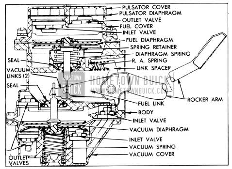
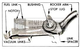
The fuel section is located above the vacuum section of the 1953 Buick pump assembly. It has a built-in air dome with a diaphragm to dampen out pulsations in the fuel stream. The fuel and vacuum sections form two separate, independently operated diaphragm type pumps, which are combined in one compact unit. The single rocker arm actuates both the fuel and the vacuum sections through separate links which permit each section to function independently. See figure 3-11.
1953 Buick Type DJ Fuel and Vacuum Pump
Operation of Fuel Section of 1953 Buick Pump
The fuel section of the 1953 Buick pump draws gasoline from the tank and supplies it to the carburetor in sufficient quantity to meet engine requirements under all operating conditions. The principle parts of the fuel section are shown in figure 3-11.
The rocker arm spring and the link spacer hold the rocker arm in constant contact with the eccentric on the engine camshaft sprocket so that the rocker arm swings up and down as the camshaft rotates. As the arm swings upward it bears against a shoulder on the fuel link which is pivoted on the rocker arm bushing. The fuel link swings downward, thereby pulling the fuel diaphragm downward by means of the connecting pull rod.
Downward movement of the fuel diaphragm compresses the diaphragm spring and also creates a vacuum in the fuel chamber above the diaphragm. The vacuum causes the outlet valve to close and causes fuel from the gasoline tank to enter the fuel chamber through the inlet valve.
As the rotating eccentric permits the rocker arm to swing downward the arm releases the fuel link; it cannot move the link upward. The compressed diaphragm spring then exerts pressure on the diaphragm and the fuel in the chamber above diaphragm. This pressure closes the inlet valve and forces fuel out through the outlet valve to the carburetor.
Since the fuel diaphragm is moved upward only by the diaphragm spring, the pump delivers fue1 to the carburetor only when the pressure in the outlet line is less than the pressure maintained by the diaphragm spring. This condition arises when the carburetor float needle valve is not seated and the fuel passage from the pump into the carburetor float chamber is open. When the needle valve is closed and held in place by the pressure of the fuel on the float, the pump builds up pressure in fuel chamber until it overcomes the pressure of the diaphragm spring. This pressure results in almost complete stoppage of diaphragm movement until more fuel is needed. Normal diaphragm stroke is approximately 1/64”.
The air dome with diaphragm in the top of fuel pump provides a pocket in which fuel under pressure can compress a certain volume of air. When the pressure is relieved (pump on suction stroke) the pocket of compressed air pushes the fuel on to its destination. The air dome minimizes flow variations experienced with two-cycle pump stroke and increases the pump output.
Operation of Vacuum Section of 1953 Buick Pump
The vacuum section of the 1953 Buick pump acts as a booster when engine manifold vacuum is insufficient to operate the windshield wipers at proper speed. This section is a double acting pump since it is effective on both the upward and downward movement of the diaphragm. The principle parts are shown in figure 3-11.
As previously explained (subpar. b), the rocker arm swings up and down as the engine camshaft rotates. As the arm swings upward it bears against shoulders on the two vacuum links which are pivoted on the rocker arm bushing. The vacuum links swing downward thereby pushing the vacuum diaphragm downward by means of the connecting rod.
Downward movement of the diaphragm compresses the diaphragm spring, which then pushes the diaphragm upward as the rotating operating eccentric permits the rocker arm to swing downward. The rocker arm cannot move the vacuum links upward. Upward and downward movement of the diaphragm produces a pumping action in the air chambers on both sides of the diaphragm.
When the windshield wiper control valve is opened and the diaphragm is moved downward by the rocker arm and links, air is drawn through the windshield wiper motor into the upper air chamber through the inlet valve in pump body. At the same time, air is exhausted from the lower air chamber into the engine manifold through the outlet valve in the vacuum cover. As the spring moves the diaphragm upward, air is drawn into the lower air chamber through the inlet valve in the cover, while air is exhausted from the upper chamber through the outlet valve which opens into the pump body from which it exhausts into the crankcase.
When the windshield wiper control valve is closed, or when engine manifold vacuum is sufficient to operate the wiper motor, vacuum holds the diaphragm in the downward position so that the rocker arm cannot actuate the vacuum links. The 1953 Buick vacuum pump remains inactive until low manifold vacuum permits the diaphragm spring to push the diaphragm upward.
3-12 1953 BUICK FUEL PUMP INSPECTION AND TEST
If the 1953 Buick fuel pump is suspected of delivering an improper amount of fuel to the carburetor, it should be inspected and tested on the engine, as follows:
- Make certain that there is gasoline in the tank.
- With engine running, inspect for leaks at all gasoline feed pipe connections at gasoline tank, 1953 Buick fuel pump, gasoline filter, and carburetor. Tighten any loose connections. Inspect the flexible connection in feed line and all pipes for dents or kinks which would restrict the flow of fuel. Air leaks or restrictions on suction side of 1953 Buick fuel pump will seriously affect pump output.
- Inspect for leaks at 1953 Buick fuel pump diaphragm flange. Tighten the cover screws alternately and securely. Do not use shellac or any other adhesive on diaphragm.
- Clean the gasoline filter at carburetor (par. 3-7).
- Disconnect pump-to-carburetor pipe. Ground primary terminal of distributor with jumper wire so that engine can be cranked without firing. Place suitable container at end of pipe and crank engine a few revolutions. If no gasoline, or only a little, flows from pipe the feed pipes are clogged or fuel pump is inoperative. Before condemning the fuel pump, disconnect feed pipes at pump and blow through them with air hose to make sure that pipes are clear.
- If gasoline flows in good volume from pipe at carburetor it may be assumed that the 1953 Buick fuel pump and feed pipes are okay; however, it is advisable to make the following “static pressure” test to make certain that fuel pump is operating within specified pressure limits.
- Attach a suitable pressure gauge to the disconnected end of gasoline pipe at carburetor. Run engine at 450 and 1000 rpm on gasoline in carburetor bowl and note reading on pressure gauge.
- If 1953 Buick fuel pump is operating properly the pressure will be 4 to 5 pounds and will remain constant at speeds between 450 and 1000 rpm. If pressure is too low or too high, or varies materially at different speeds, the pump should be removed for repairs (par. 3-14). NOTE: If pressure gauge is connected at pump outlet instead of at end of feed pipe the pressure should be 4 1/2 to 5 1/2 pounds.
3-13 1953 BUICK VACUUM PUMP INSPECTION AND TEST
To test the vacuum section of pump, fully open the windshield wiper valve and observe the wiper blades while alternately idling and accelerating the engine. Operation of the windshield wiper should continue at nearly constant speed regardless of the engine speed or throttle opening. NOTE: A dry windshield has the effect of slowing wiper blades in comparison with operation over a wet windshield. Consider this when testing, or wet the windshield by spraying with water. If windshield wiper does not operate properly make the following inspection and test.
- Make certain that wiper hoses are properly connected at pump, wiper motor, and control on instrument panel, and that connections are air tight. Replace cracked or deteriorated hose.
- Make certain that wiper transmission links or cables are not binding against anything under the cowl. If cables are used, make sure they are correctly attached to the wiper motor and are properly placed in pulleys on cable tensioners and transmissions.
- If windshield wiper does not operate properly after all points of leakage have been corrected, detach both pipes at 1953 Buick vacuum pump and join them with a piece of rubber hose. Slowly operate engine from idle to about 25 MPH speed; the wiper should run at full speed operating on engine vacuum only. If it does not, it can be assumed that the wiper motor, or tubing is defective. The pump vacuum section is inoperative if the windshield wiper operates properly on engine vacuum but not on pump vacuum.
- A further test of vacuum pump may be made by attaching a vacuum gauge to the inlet port (port connected to wiper motor), with outlet pipe disconnected. CAUTION: Always make this test of 1953 Buick vacuum pump with the outlet open.
- With engine operating at equivalent of 20 MPH road speed, the gauge should show 7 to 12 inches of vacuum. Less than 7 inches of vacuum indicates an inoperative 1953 Buick vacuum pump.
3-14 DJ FUEL AND VACUUM PUMP REPAIRS
After removal of 1953 Buick pump from engine and before disassembly is started, plug all openings and thoroughly wash exterior of pump with cleaning solvent to remove all dirt and grease.
Removal of Vacuum Cover, Valves, and Diaphragm
- Replace two diametrically opposite vacuum cover screws with 10-32 x 1 1/2″ screws and turn them down snug. Remove all other cover screws, then alternately loosen the 1 1/2″ screws until pressure of diaphragm spring against cover is fully released. See figure 3-12.
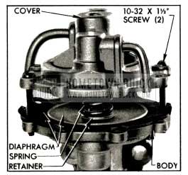
1953 Buick Removing Vacuum Cover
1953 Buick Vacuum Valves and Pull Rod Seal
Removal of Fuel Cover, Valves, and Diaphragm
NOTE: The vacuum cover must be removed (subpar. a) before removing the fuel cover.
- Mark edges of fuel cover and pump body with file so that cover may be reinstalled in its original position on body. See figure 3-13.
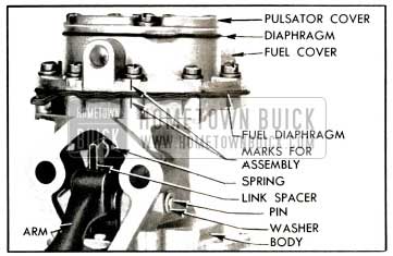
1953 Buick Fuel Section of Pump
Removal of Rocker Arm and Links
- File riveted end of rocker arm pin flush with steel washer (fig. 3-13), or cut off end with a 3/8” drill, then drive out pin with a drift punch and hammer.
- Remove rocker arm and links, and rocker arm spring from pump body. Remove bushing which holds rocker arm and links together.
Inspection of 1953 Buick Pump Parts
- Clean and rinse all metal parts in solvent. Blow out all passages with air hose.
- Inspect pump body, fuel cover, and vacuum cover for cracks, breakage, and distorted flanges. Examine all screw holes for stripped or crossed threads. Replacement of pump assembly is advisable if one of the three main castings is not serviceable.
- Inspect the rubber pull rod oil seals in pump body. See figure 3-16. If damaged or of doubtful condition, pry out the metal retainer and discard the rubber seal. Place new seal in body with concave side outward, press metal retainer down firmly into body with the flat end of a rod 7/8″ in diameter, then stake body metal in four places around the retainer.
- Inspect rocker arm for wear or scores at camshaft pad, at point of contact with links, and at pivot hole. Inspect bushing for wear.
- Discard links if pump has been in service for high mileage. Amount of wear of these parts cannot be determined visually.
- Discard diaphragm in faulty section of pump, or both diaphragms if service mileage is high.
- Discard valve and cage assemblies as these parts cannot be visually checked for wear.
- Discard rocker arm and diaphragm springs, as removed, because old springs may be distorted, weak, or corroded.
Installation of Rocker Arm and Links
- Insert drilled end of fuel link (short) into link spacer, place one vacuum link (long) on each side of spacer, line up holes in these parts, then slide them between jaws of rocker arm and install the pin bushing. The notches in all links must be on same side as the stop lug on rocker arm, and link spacer must be on opposite side. See figure 3-14.
1953 Buick Rocker Arm Links, Spacer, and Bushing Assembled
Installation of Fuel Diaphragm, Valves, and Cover
NOTE: Always install the fuel diaphragm and cover before the vacuum diaphragm and cover.
- Soak new fuel and pulsator diaphragms in clean kerosene or fuel oil.
- Place diaphragm spring on oil seal retainer in body, place cup shaped spring retainer on top of spring, then push fuel diaphragm pull rod through these parts with flat of rod at 90 degrees to links in body. Hook pull rod to the short, center fuel link.
- Place a new valve gasket in each valve seat in fuel cover. Place one valve in seat nearest the inlet port with the spring cage side facing up. Place another valve in the outlet valve seat with the spring cage side down. See figure 3-15.
1953 Buick Valves in Fuel Cover
Tighten screws alternately on diametrically opposite sides until all are tight before releasing the rocker arm.
CAUTION: Diaphragm must be held in flexed position until all screws are tightened, otherwise diaphragm may be stretched too tight and cause pump to deliver excess pressure.
Installation of Vacuum Diaphragm, Valves, and Cover
- Soak new vacuum diaphragm in clean kerosene or fuel oil.
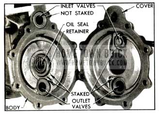
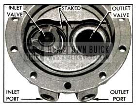
- Place a new valve gasket in each valve seat in vacuum cover. Place one valve in seat nearest inlet port with the spring cage side facing up. Place another valve in the outlet valve seat with the spring cage side down. Press valves down firmly against gaskets, then stake cover metal in four places around each valve. See figure 3-16.
- Install gasket and valve, with spring cage side down, in seat farthest from mounting flange in pump body, then stake in place. See figure 3-16. Do not install the inlet valve adjacent to mounting flange at this time.
- Hold vacuum diaphragm so that the ear is toward rocker arm and flat on pull rod is at 90 degrees to links as pull rod is pushed through oil seal in pump body.
- Use a pipe on rocker arm to position inner ends of the two vacuum links about l2 inch below oil seal and hook slotted end of pull rod over both vacuum links.
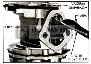
- Depress rocker arm and insert hooked end of Diaphragm Flexing Tool No. PT-8 (AC) between rocker arm and the stop boss in body, then release rocker arm. The vacuum diaphragm will then be in a flat or level position.
If Tool No. PT-8 is not available, a piece of metal having a short bent end %2 inch thick may be used. See figure 3-17.
1953 Buick Vacuum Diaphragm Flexing Tool in Place
- Lift ear of diaphragm at rocker arm and install a valve in valve seat in body. Do not use a gasket or stake this valve in place as it is retained and sealed by the diaphragm.
- Place spring retainer over the riveted end of diaphragm pull rod, place diaphragm spring on the retainer, then place vacuum cover over the spring.
- With projection of vacuum cover placed toward rocker arm, install two 10-32 x 1 1/2″ screws in diametrically opposite screw holes (fig. 3-12) and alternately turn screws down until cover is close to the diaphragm.
CAUTION: As cover is installed make certain that diaphragm is centralized. If diaphragm is pulled to one side it may cause the diaphragm spring to rub on cover and produce a squeak during pump operation.
- Install regular screws and turn down until heads just engage the lockwashers. Remove long screws and install short ones. Be sure that screws pass through holes in fabric of diaphragm without chewing.
- Remove the flexing tool. The pressure of the vacuum spring will then flex the diaphragm the correct amount.
- Tighten all cover screws alternately on diametrically opposite sides, turning each screw several turns at a time, until all are securely tightened.
Testing Repaired 1953 Buick Fuel and Vacuum Pump
Bench tests of the 1953 Buick fuel and vacuum sections of the pump require equipment which is not available in service stations; therefore, tests must be made after installation of pump assembly on an engine. Test fuel section of pump as described in paragraph 3-12. Test vacuum section of 1953 Buick pump as described in Paragraph 3-13.
Leave A Comment
You must be logged in to post a comment.