GROUP 5 – 1953 BUICK REAR AXLE ASSEMBLY
5-1 1953 BUICK REAR AXLE CHANGES
The 1953 Buick rear axle assembly is essentially the same design as the 1952 rear axle assembly; however, a number of changes were made which affect interchangeability of parts and some service procedures. This section will describe the changes and their related service procedures. For all other information refer to Group 5 in the 1952 Buick Shop Manual.
Propeller Shaft Seal
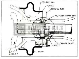
A new propeller shaft seal was used at start of 1953 production. The new seal is tightly fitted into a recess in the torque tube front flange. Approximately half of the seal retainer projects into a recess in the torque ball to act as a pilot. The universal joint seal formerly located at this point in torque ball has been eliminated. See figure 5-1.
1953 Buick Rear Axle Propeller Shaft Seal
The seal is installed with the spring loaded lip edge toward front of car, and this edge bears against a sleeve which is pressed on the propeller shaft in position to close off the splines against passage of oil. A paper gasket is used between the torque tube and torque ball.
Pinion Bearing Lock Nut and Seal
After start of production, the pinion bearing lock nut was modified to accommodate a new seal. The new seal has a revised outer retainer which provides more positive piloting during assembly, preventing cocking of the seal. The rear edge of the new outer retainer is straight, whereas the rear edge of the previous type is rolled over. Because of the slightly longer retainer of the new seal it was necessary to narrow the hex section of the bearing lock nut to provide adequate clearance. The new seal will be packaged with the modified nut in the kit furnished for service.
Differential Assembly
After 1953 production started, a new differential, propeller shaft, and third member housing assembly was introduced on all models. The change permits use of larger pinions to provide faster rear axle gear ratios. While the second design is essentially the same as the first, none of the parts are interchangeable because of differences in dimensions. At the same time this change was made, the speedometer driving worm gear was changed to 8 teeth (par. 4-1, e).
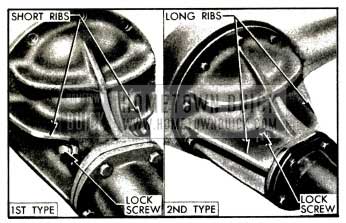
First and second differential designs may be identified by the external appearance of the carriers. In the second type, the upper side ribs are extended forward to the front flange and the pinion bearing sleeve lock screws are rotated so that the bottom screw is no longer straight down. See figure 5-2.
1953 Buick First and Second Type Differential Carriers
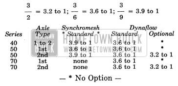
1953 Buick Rear Axle Gear Ratios
The following gear ratios are used in 1953 Buick rear axles. NOTE: The 1953 Buick rear axle ratio is indicated by numbers stamped on bottom center of axle housing.
1953 Buick Rear Axle Gear Ratios
Ring gear and pinion tooth combinations for these ratios are: 3.2 to 1= 42-13; 3.6 to 1= 43-12; 3.9 to 1=43-11.
5-2 1953 BUICK REAR AXLE SERVICE PROCEDURES
Except for the following changes caused by the previously described changes in design, the service procedures given in Group 5 of the 1952 Buick Shop Manual are to be used on the 1953 Buick rear axle assemblies.
Removal and Installation of Pinion and Propeller Shaft Assembly
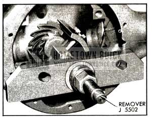
The new design of propeller shaft seal and availability of new tools makes it unnecessary to disconnect the torque tube from the torque ball in order to remove and install the pinion and propeller shaft assembly.
Remover and Replacer J 5502 is designed to pull the pinion and shaft assembly as shown in figure 5-3.
1953 Buick Removing Pinion and Shaft
Since it is definitely recommended that the assembly be pressed and not driven during installation, this tool is also designed to press the assembly into place as shown in figure 5-4.
Because of the increased diameter of the second type pinion gear, a new Pinion Bearing Spacer J 5499 must be inserted between the rear bearing and the pinion gear during installation so that the bearing will be pushed into place without binding against the spacer on pinion shaft. See figure 5-4.
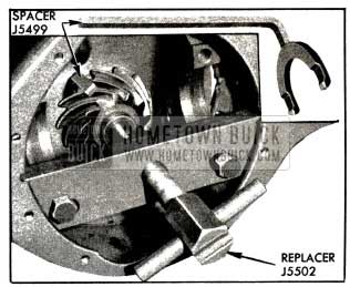
1953 Buick Pressing Pinion and Shaft into Place
When the pinion and shaft assembly is being installed, be very careful to start the shaft through the front seal in torque tube without damaging the seal retainer and thereby causing an oil leak. If the axle assembly is under the car, the universal joint yoke will guide the propeller shaft so that the sleeve will enter the seal centrally. If axle assembly is not under car, however, a second man should guide the shaft as the sleeve enters the seal, to avoid damaging the seal.
Checking Pinion Setting With Gauge
After installation, the pinion setting must be checked with Gauge J 681-A or J 2197 as described in Paragraph 5-15 of the 1952 Buick Shop Manual, observing the following points.
(1) First Type Carrier. When checking pinion setting in the first type carrier use pinion setting table given in figure 5-23 of the 1952 Buick Shop Manual.
(2) Second Type Carrier. When checking pinion setting in the second type carrier use the new Adapter J 2197-9 with Clamp J 2197-8 and also use the new pinion setting table given in figure 5-5 of this manual. The new table is based on a nominal setting of .317 for Gauge J 681-A and .864 for Gauge J 2197.
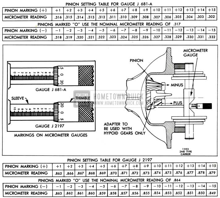
1953 Buick Pinion Setting Tables for Second Type Carrier
Ring Gear Adjustment
Refer to paragraph 5-16 of the 1952 Buick Shop Manual for ring gear adjustment procedure. When adjusting ring gear in a second type carrier observe the -following points.
Backlash must not be less than .006″ nor more than .011″, with .007″ to .009″ preferred. Backlash must not vary more than .003″ around the ring gear. Side bearing preload is 2 to 3 notches tight; one notch on adjuster represents about .0035″ change in backlash. The new Adjuster Wrench J-1365-A must be used for adjusting backlash; do not use a punch on adjusters. Tighten bearing cap bolts to 100-120 ft. lbs. torque.
Leave A Comment
You must be logged in to post a comment.