SECTION 11-A 1953 BUICK ACCESSORIES MAINTENANCE – EXCEPT RADIO
NOTE: For accessories not listed above refer to Section 11-A in the 1952 Buick Shop Manual.
11-1 1953 BUICK HEATER AND DEFROSTER
The 1953 Buick heater and defroster installations are essentially the same as described in Section 11-A in the 1952 Shop Manual. The only change requiring service information is in the method of connecting the water hoses so that the heater water system is completely separated from the Dynaflow oil cooler water system. Figure 11-1 shows the heater and defroster water hose connections for all series.
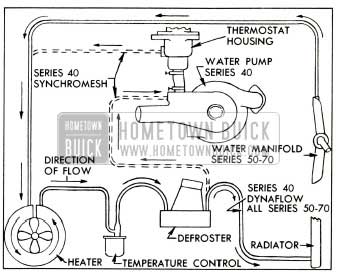
1953 Buick Heater and Defroster Hose Connections
11-2 1953 BUICK AIR CONDITIONER
The 1953 Buick Air Conditioner is factory installed optional equipment. Locations of the various units of the 1953 Buick Air Conditioner system and their connecting pipes are shown in figure 11-2. Figure 11-3 shows the electrical control circuits, which are entirely separate from all other chassis and body wiring circuits.
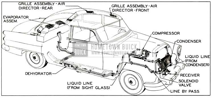
1953 Buick Air Conditioner Installation
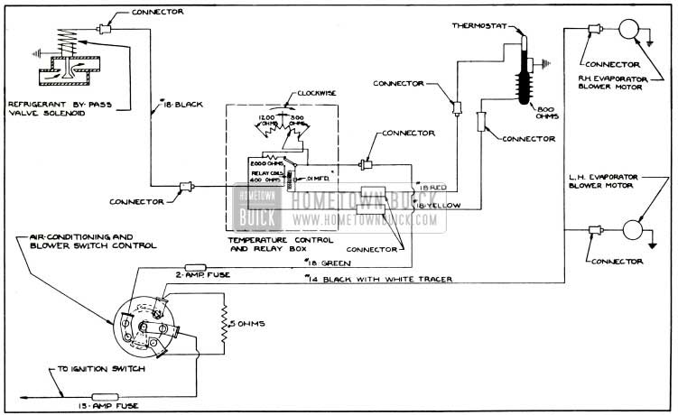
1953 Buick Air Conditioner Control Circuit Diagram
A complete description of the 1953 Buick Air Conditioner system with all necessary service information is given in the separate 1953 Buick Air Conditioning Manual (B.P.S. 7.22). This manual is used in Buick service training schools and is also available at Hometown Buick.
Except for the few operations given in this paragraph, all service work on the Air Conditioner system should be performed only by mechanics who have been trained in Buick or other air conditioning schools. Whenever a pipe is disconnected from any unit except the compressor, liquid or vaporized refrigerant will escape unless the proper procedure is used. Any work involving the handling of refrigerant requires special equipment and a knowledge of its proper use.
Operating Instructions
Operation of the 1953 Buick Air Conditioner is controlled by two switch knobs located on instrument panel just above the steering column. See Figure 11-4.
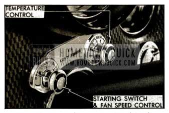
1953 Buick Fan and Temperature Control Switch
To start 1953 Buick Air Conditioner operation, turn the left hand switch knob to “FAST” or “SLOW” as required by car temperature. For maintaining comfort after car is cooled down, the “SLOW” fan speed should be used except in the most extreme summer heat.
The temperature level of the air supply may be set at any point between 64° and 78° F to suit the personal comfort of car occupants. This is done by turning the right hand knob (fig. 11-4). It is not necessary to set the temperature control to coldest position in order to cool out the car. When the knob is set for the desired temperature level the Air Conditioner will soon bring the interior temperature to that level and will maintain it until the knob is given a different setting.
If car has been standing in the sun it may be aired out by opening doors and windows. When the Air Conditioner is started, however, all windows and ventilators must be closed in order that all outside air entering the passenger compartment will be admitted only through the Air Conditioner.
Distribution of cooling air is controlled by two ceiling vent panels on each side of body. The rear panel has a shutter which may be opened or closed by the protruding button. The front panel does not have the shutter. Air directors in front and rear panels may be turned in any direction desired or may be closed by turning to the “OFF” position. The front panels have an additional air director which may be rotated to any desired position, but cannot be closed.
“Winterizing” the 1953 Buick Air Conditioner
During winter months the air valves should be closed so that cold air will not be drawn into the passenger compartment through the outside scoops. The air valves are controlled by knobs protruding from the cover panel of the conditioner unit in car trunk compartment. Valves are closed when knobs are set at “WINTER” position.
When average temperatures are consistently below 45° F., the Air Conditioner compressor should be idled by removal of the drive belts and installation of the short spare belt which is supplied in car equipment. This short belt bypasses the compressor pulley to drive the fan and generator.
Cleaning the 1953 Buick Air Conditioner
If a car is operated where the air is dusty or insect-laden, the transparent ducts along the rear window and the air return grille filters may need cleaning.
The transparent ducts may be removed for cleaning by removing two screws located at upper end of each duct.
The air return grille filters may be removed for cleaning by opening the car’s trunk and taking off the cooling-unit cover. Reach up under the grille and slide out the filters; then clean them with a gentle spray of water and gently shake them dry. Careful handling of the filters will preserve the precisely calculated filter structure that controls a balanced ratio of outside air to recirculated air_ in the system.
Removal and Installation of 1953 Buick Air Conditioning Compressor
Whenever it becomes necessary to remove the 1953 Buick Air Conditioner compressor so that work can be done on the engine the following instructions must be carefully followed. Whenever it becomes necessary to lower the engine for such work as removal of transmission, the lines should be disconnected from the compressor to avoid damaging the flexible adapters in these lines.
- Remove protective caps and firmly close both pressure line shut off valves on compressor by turning valves clockwise. See figure 11-5.
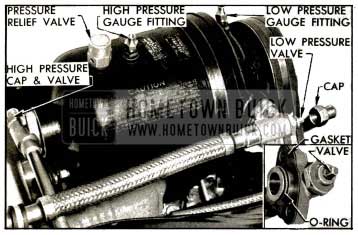
1953 Buick Compressor Line Connections
In this case remove the cap from the high pressure gauge fitting (fig. 11-5) and depress the valve stem to relieve pressure in compressor.
- Loosen the belts and remove compressor from its mounting on engine. Carefully cover all openings in compressor and shut off valves, preferably using CLEAN aluminum foil.
- When compressor is reinstalled, use new O-ring and gasket on each shut off valve. Apply Frigidaire oil to O-ring and gasket for easy installation. Adjust belts to %” deflection midway between fan and compressor pulleys.
CAUTION: Make sure that both shut off valves are fully opened before starting engine.
- After operating compressor for ten minutes at 1600-1700 engine RPM apply Buick leak detector solution (Group 9.282) around the shut off valve flanges. If bubbles form within a few seconds a gas leak exists which must be corrected.
which wheel lock and bolt/nut is for a 53 buick