SECTION 10-D 1953 BUICK GENERATING SYSTEM
NOTE: This section applies to the Series 50-70 12-volt generating system. For Series 40 6-volt generator information refer to Section 10-D in the 1952 Buick Shop Manual.
10-20 THE 1953 BUICK GENERATING SYSTEM
The 1953 Buick generating system restores to the battery the energy used in cranking the engine. It also supplies current to carry the electrical load of the ignition, lights, signaling devices, and accessories, at operating speeds above 25 MPH up to the limit of the generator’s capacity. At speeds below 25 MPH the output of generator is not sufficient to carry the electrical load of all units, therefore the battery supplies the additional current required.
The 1953 Buick generating system consists of the generator (par. 10-21), generator regulator (par. 10-22), charge indicator, battery (par. 10-14), the wires and cables connecting these units, and the battery ground cable and ground through engine crankcase which completes the circuit. See figure 10-9.
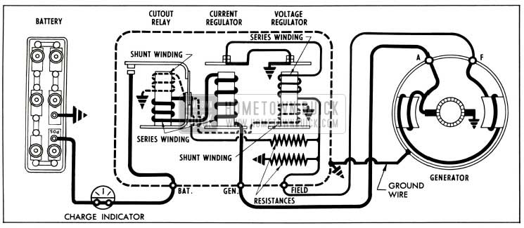
1953 Buick Generator Regulator In Generating Circuit
The charge indicator indicates charging current going into the battery and the current leaving battery, except when cranking the engine. The charge indicator does not indicate total charging rate of generator since current supplied by generator to electrical units other than the battery does not pass through the indicator.
10-21 DESCRIPTION OF 1953 BUICK GENERATOR
The 1953 Buick generator is a two-brush, two-pole shunt wound unit which is capable of delivering 30 amperes at 14 volts when hot.
The maximum output of generator is controlled by the current regulator; however, the generator does not normally deliver the maximum output because the voltage regulator controls output in accordance with the requirements of the battery and the current consuming units in operation. See figure 10-6.
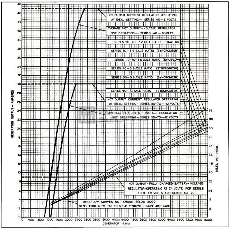
1953 Buick Generator Output Chart
The 1953 Buick generator pulley drives a fan which draws a draft of air through the generator to carry away the heat produced during operation. This ventilation permits the generator output to be increased to higher values than would be possible in a non-ventilated generator of the same size.
The armature shaft is supported by an annular ball bearing in the drive end frame and a bronze bushing in the commutator end frame. The bearing and the bushing are provided with hinge cap oil cups for periodic application of a few drops of light engine oil.
The two brushes are mounted in individual brush holders attached to the field frame and are held in contact with the commutator by spring loaded brush arms. One brush holder is grounded to the frame by the attaching rivet. The opposite brush holder is attached to the frame by a rivet and the “A” terminal screw but is completely insulated from the frame. The brush in this holder is connected to the field coils and to the “A” terminal screw. See figure 10-11. Each field coil is held in place by a pole shoe attached to the frame by a large screw, and the coil is separated from its pole shoe by heavy insulation. See figure 10-7.
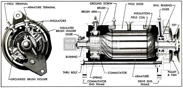
1953 Buick Generator, Sectional View
The 1953 Buick generator is mounted on a bracket on right side of engine and is driven by the fan belt. The method of mounting permits generator to be moved in or out to adjust tension of fan belt.
10-22 DESCRIPTION OF 1953 BUICK GENERATOR REGULATOR
The 1953 Buick generator regulator is mounted on the left rear fender skirt and is cushioned by rubber to dampen the noise which is caused when the regulators operate. The regulator is grounded to the fender skirt through two of the attaching bolts, and to insure positive ground the base of regulator is also connected by a wire to the generator frame.
The 1953 Buick generator regulator contains a cutout relay, current regulator, and voltage regulator, all mounted on one base and enclosed by a sheet metal cover. See figure 10-8.
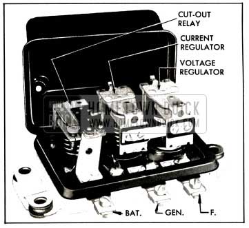
1953 Buick Generator Regulator
These three devices are magnetic switches whose functions and operations are as follows:
1953 Buick Cutout Relay
The 1953 Buick cutout relay opens the circuit to prevent the battery from discharging to ground through the generator whenever the engine is stopped or generator is operating at such low speed that its voltage is less than voltage of battery. When the voltage of generator is slightly greater than battery voltage the relay closes the circuit so that generator can furnish current to the electrical system.
The 1953 Buick cutout relay has a series or current winding of a few turns of heavy wire, and a shunt or voltage winding of many turns of fine wire, both assembled on the same core. The shunt winding is connected between generator armature and ground so that generator voltage is impressed upon it at all times. The series winding is connected so that all generator output current must pass through it. It is connected to a flat steel armature which has a pair of contact points through which current passes to the battery and other electrical units. The contact points are held open by armature spring tension when the unit is not operating. See figure 10-9.
1953 Buick Generator Regulator In Generating Circuit
When the 1953 Buick generator begins to operate, voltage builds up and forces current through the shunt winding, thereby magnetizing the core. When the voltage reaches the value for which the relay is set, the magnetism is strong enough to overcome the armature spring tension and pull the armature toward the core, thereby closing the contact points. Generator current now flows through the series winding of relay in the right direction to add to the magnetism holding the points closed, and passes on to the battery and other electrical units in operation.
When the 1953 Buick generator slows to engine idling speed, or stops, current begins to flow from the battery back through the generator, reversing the current flow through the series winding. This reduces the magnetism of the relay core to the extent that it can no longer hold the contact points closed against armature spring tension. The points are separated and the circuit broken between the generator and battery.
1953 Buick Current Regulator
The 1953 Buick current regulator automatically controls the maximum output of the generator. When the current requirements of the electrical system are large and the battery is low, the current regulator operates to protect the generator from overload by limiting its output to a safe value.
The 1953 Buick current regulator has one series winding of heavy wire through which the entire generator output flows at all times. This winding connects to the series winding in the cutout relay, described above. Above the winding core is an armature, with a pair of contact points which are held together by spring tension when the current regulator is not operating. When current regulator is not operating and the contact points are closed, the generator field circuit is directly grounded so that generator may produce maximum output, unless further controlled by the voltage regulator described below. See figure 10-9.
When the 1953 Buick generator output increases to the value for which the current regulator is set, the magnetism of the current winding is sufficient to overcome the armature spring tension. The armature is pulled toward the winding core so that the points are separated. The generator field circuit must then pass through a resistance, which reduces the flow through the field coils and thereby reduces the output of generator. This reduces the magnetic strength of the current winding so that spring tension again closes the contact points, directly grounding the generator field circuit and increasing generator output. This cycle is repeated 150 to 250 times a second, and the action limits the 1953 Buick generator output to the value for which the regulator is set.
The 1953 Buick current regulator has a bi-metal hinge on the armature for thermostatic temperature control. This automatically permits a somewhat higher generator output when the unit is cold, and causes the output to drop off as the temperature increases.
The current regulator operates only when the condition of battery and the load of current-consuming units in operation require maximum output of the generator. When current requirements are small, the voltage regulator controls generator output. Either the current regulator or the voltage regulator operates at any one time; both regulators never operate at the same time.
1953 Buick Voltage Regulator
The 1953 Buick voltage regulator limits the voltage in the charging circuits to a safe value, thereby controlling the charging rate of the generator in accordance with the requirements of the battery and the current-consuming electrical units in operation. When the battery is low, the generator output is near maximum but as the battery comes up to charge, and other requirements are small, the voltage regulator operates to limit the voltage, thereby reducing the generator output. This protects the battery from overcharge and the electrical system from high voltage.
The 1953 Buick voltage regulator consists of two windings assembled on the same core, an armature and a set of contact points, and a fixed resistance. The voltage winding consists of many turns of fine wire connected so that generator voltage is impressed on it at all times. The series winding, having a few turns of heavy wire, carries the generator field current directly to ground when the regulator contact points are closed. A contact point on the armature, which is located above the winding core, is held in contact with a stationary contact point by armature spring tension when the voltage regulator is not operating. See figure 10-9.
When the generator voltage reaches the value for which voltage regulator is set, the combined magnetic pull of the voltage and series windings is sufficient to overcome the armature spring tension, so that the armature is pulled toward the core and the contact points are separated. The instant the points separate, the field current flows to ground through the resistance. This reduces the current flow through the field coils and decreases generator voltage and output.
As soon as the field current stops flowing through the series winding, the magnetic pull of this winding collapses. In addition, the reduced voltage in the circuit causes a weakening of the magnetic field of the voltage winding in the regulator. The resulting loss of magnetism permits the springs to pull the armature away from the core and close the contact points again, thereby directly grounding the generator field so that generator voltage and output increases.
This cycle is repeated 150 to 250 times a second, causing a vibrating action of the armature, and holds the voltage to a constant value. By maintaining a constant voltage, the voltage regulator continues to reduce the generator output as the battery comes up to charge. When the battery reaches a fully charged condition, the voltage regulator will have reduced the generator output to a relatively few amperes.
The voltage regulator has a bi-metal armature hinge for thermostatic temperature control. This automatically permits regulation to a higher voltage when the unit is cold, and a lower voltage when hot, because a high voltage is required to charge a cold battery.
As previously stated, the current and voltage regulators do not operate at the same time. When current requirements are large, the generator voltage is too low to cause voltage regulator to operate, therefore the current regulator operates to limit maximum output of generator. When current requirements are small, the generator voltage is increased to the value which causes voltage regulator to operate. The generator output is then reduced below the value required to operate the current regulator, consequently all control is then dependent on the operation of voltage regulator.
Resistances
The current and voltage regulator circuits use a common resistance which is inserted in the field circuit when either regulator operates.
A second resistance is connected between the regulator field terminal and the relay base, which places it in parallel with the generator field coils.
The sudden reduction in field current occurring when either the current or voltage regulator contact points open, is accompanied by a surge of induced voltage in the field coils as the strength of the magnetic fields change. These surges are partially dissipated by the two resistances, thus preventing excessive arcing at the contact points.
10-23 PERIODIC INSPECTION AND TEST OF 1953 BUICK GENERATOR – ON CAR
As a general rule, the 1953 Buick generator should be inspected and tested every 5000 miles to determine its condition; however, the type of service in which some generators are used may make more frequent inspection advisable. High speed operation, excessive dust or dirt, high temperatures and operation of generator at or near full output most of the time are all factors which increase bearing, commutator and brush wear.
Inspection of 1953 Buick Generator
The following inspection will disclose whether the 1953 Buick generator is in proper condition for service or in need of removal for repairs.
- Using a good light and a mirror, inspect the commutator through the openings in the commutator end frame. Low or unsteady output may result if the commutator is coated with grease or dirt, or is rough, out of round, or has high mica between the bars. If commutator bars are burned an open circuit is indicated.
- Inspect commutator end of generator for thrown solder, indicating that generator has been overheated due to excessive output.
Excessive output usually results when the generator field is grounded, either internally or at the regulator. If this is indicated, disconnect the wire at “F” terminal of generator or regulator and run engine at medium speed. If generator output drops off the regulator is at fault but if output remains high the field is grounded internally in generator.
- Check condition of brushes; make sure they are not binding in holders and that they are resting on the commutator with sufficient tension to give good, firm contact. Brush leads and screws must be tight. If the brushes are worn down to one-half their original length, compared with new brushes, the generator must be removed for installation of new brushes.
- If the commutator or brushes are in bad condition, other than being dirty, the generator should be removed for repairs (par. 10-25). If these parts are only dirty, however, they may be cleaned without removal of generator.
Clean off any grease with a cloth soaked with carbon tetrachloride or other non-inflammable solvent. While engine is running, polish commutator with a brush seating stone or with a strip of 2/0 sandpaper placed over a smooth piece of thin wood. Never use emery cloth on the commutator because it will cause arcing, burning, and rapid wear of the brushes. After cleaning commutator blow out all dust from generator.
- Check fan belt for condition and proper tension (fig. 10-10), and make certain that all generator mounting bracket and brace bolts are tight. A loose fan belt will permit belt slippage, resulting in rapid belt wear and low or erratic generator output. An excessively tight belt will cause rapid belt wear and rapid wear of generator and water pump bearings. NOTE: If belt requires adjustment, first loosen belt so that generator pulley is free, then check pulley for tightness and check generator bearings for freeness of rotation and excessive side play. Tight or excessively worn bearings should be cleaned or replaced.
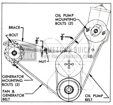
1953 Buick Fan Belt Adjustment
Testing 1953 Buick Generator Output and Generator Circuit Wiring
After the inspection given above it is advisable to test the 1953 Buick generator for output and the circuit wiring for excessive resistance. Before making the following tests make certain that battery specific gravity is not less than 1.250.
- Disconnect wire from 1953 Buick generator regulator terminal marked “BAT” and connect an ammeter in series with this terminal and the disconnected wire.
- Connect jumper wire between regulator terminal marked “F” and base plate of regulator so that current and voltage regulators cannot operate to control generator output.
- Start engine and with all electrical units turned off slowly increase engine speed until ammeter registers 30 amperes, which should be reached at approximately 1100 RPM of engine when generator is HOT, or at slightly lower speed when generator is cold. CAUTION: Do not exceed 1300 RPM of engine while “F” terminal is grounded.
- If 30 amperes cannot be obtained at approximately 1100 RPM of engine check fan belt for proper tension (fig. 10-10). If fan belt is not slipping the generator does not have proper output. Remove 1953 Buick generator for bench test (par. 10-24) and make necessary corrections before attempting any adjustment of generator regulator.
- Slowly increase engine speed until ammeter registers 20 amperes and note engine speed at this point, then stop the engine.
- Disconnect ammeter and reconnect loose wire to “BAT” terminal of regulator. Leave jumper wire connected between “F” terminal and regulator base. Momentarily bridge between “BAT” and “GEN” terminals of regulator to polarize the 1953 Buick generator.
- Start engine, then connect a voltmeter negative (-) lead to the battery positive (+) terminal and connect voltmeter positive (+) lead to “A” terminal of generator.
- Slowly open throttle until engine speed is the same as when 20 amperes was obtained in step 5. At this point note voltmeter reading.
- The voltmeter indicates the voltage drop in the generator to battery wiring. If the reading is greater than .8 volt there is excessive resistance at some point in this circuit. The cause of high resistance must be located and eliminated to insure proper charging of the battery.
- Disconnect voltmeter and remove jumper wire.
10-24 BENCH TEST OF 1953 BUICK GENERATOR
The following inspection and test of 1953 Buick generator, after removal from car, may be used to determine the cause of unsatisfactory output before generator is disassembled.
- Inspect condition of brushes and commutator as described in paragraph 10-23. If brushes and commutator are in satisfactory condition and the cause of trouble is not apparent proceed to the following steps.
- Place piece of cardboard between commutator and grounded brush. Using test lamp and points, check for grounds with test points on “A” terminal and generator frame. If lamp lights, the generator is internally grounded. Locate the ground by insulating the other brush also, and checking the brush holders, armature, commutator and field separately.
- If generator is not grounded, check the field for open circuits by placing one test lamp point on the “F” terminal and the other point on the insulated brush holder to which the other end of field coil is connected. If lamp does not light the field has open circuit. If the open circuit is due to a broken lead or bad connections, it can be repaired but if the open circuit is inside one of the field coils the coil must be replaced.
- If the field is not open, .check for a short circuit by connecting a 12-volt battery and an ammeter in series with the field coils. Proceed with care since a shorted field may draw excessive current which might damage the ammeter. An ammeter reading of 1.48 to 1.62 amperes indicates field is satisfactory; a higher reading indicates a short circuit.
- If the cause of trouble has not been located, disassemble generator for test of armature (par. 10-25
- If a shorted field is found be sure to check for burned contact points in the generator regulator (par. 10-26) because a shorted field may permit an excessive field current which could burn the contact points.
10-25 1953 BUICK GENERATOR REPAIRS ON BENCH
Disassembly, Cleaning and Inspection
When it is necessary to disassemble 1953 Buick generator for any reason, make a complete clean up and test to make sure all parts are in satisfactory condition. See figures 10-6 and 10-11 for identification of generator parts.
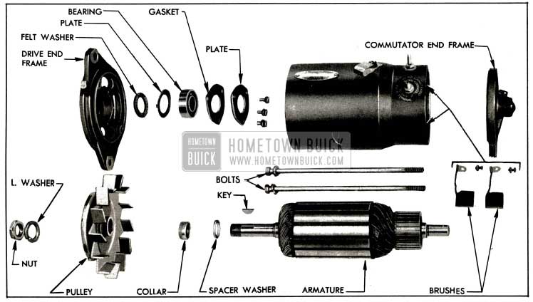
1953 Buick Generator Disassembled
- Unscrew both through bolts and remove the commutator end frame from the field frame.
- Disconnect brush leads and remove brushes from holders, then remove armature, drive end frame and pulley assembly from the field frame.
- Hold armature in vise equipped with soft jaws, and avoid excessive tightening of vise. Remove pulley not, lock washer, pulley, fan, key, collar, and drive end frame from armature shaft. Remove spacer washer.
- Remove bearing retainer plate, gasket, bearing, plate and felt washer from drive end frame.
- Thoroughly clean and inspect the ball bearing, and if satisfactory for use, pack it with high melting point ball bearing grease. Replace worn or rough bearing.
- Clean all other parts by wiping with clean cloths. The armature and field coils must not be cleaned in any degreasing compound since this might damage insulation so that a short or ground would subsequently develop.
- Carefully inspect all parts for wear or damage and make necessary repairs, or replace unserviceable parts. Any soldering must be done with rosin flux; never use acid flux on electrical connections. If brush springs are distorted or show evidence of overheating, replace them.
Testing and Repairing Armature
Before making any repairs to the armature, test it for open, shorted or grounded circuits.
Open circuits in armature are usually obvious since the open circuited commutator bars are usually burned as a result of arcing as they pass under the brushes. If 1953 Buick generator has overheated and thrown solder, the open circuit will be at connections to commutator riser bars. Repair can be affected by resoldering leads to riser bars, using rosin flux.
Test for grounds, using test lamp and points, by placing one test point on armature core and the other test point on commutator. If lamp lights, the armature is grounded. If grounds are at points where coils come out of slots in core, repairs can be made by placing insulating strips between core and coil which is grounded.
Check armature for short circuits by placing it on a growler and slowly turning armature while holding a thin strip of steel (hacksaw blade) above armature core. The steel strip will vibrate when above the area of armature core in which any short circuited coils are located. Copper or brush dust in slots between commutator bars may cause shorts between bars which can be eliminated by cleaning out the slots. Shorts at cross-over of coils at the drive end can often be corrected by bending the wires slightly and reinsulating the exposed bare wire.
If armature is otherwise satisfactory but commutator is worn, burned, out of round, or has high mica between bars, the commutator should be turned true in a lathe. After turning, undercut mica %2″, then carefully clean all dirt and copper dust out of slots. Lightly polish the commutator with 2/0 sandpaper to remove all slight burrs left by undercutting operation.
Replacement of Brush Holders
When it is necessary to replace a brush holder, drill out the attaching rivet with a No.2 drill to remove old holder from the field frame. Attach the new brush holder with the screw, lockwasher, and nut provided in the brush holder service package.
When installing the insulated brush holder place insulating bushing on attaching screw with flat side against screw head. Locate screw and bushing in hole of brush holder, force flatsided hole of insulating strip over screw threads, install parts in field frame and install lockwasher and nut on screw finger tight. Thread the terminal stud through slot in brush holder and round hole in insulating strip, then install insulating bushing, flat washer, lockwasher, and nut. Tighten attaching screw and stud nuts securely. Attach field coil and brush leads to inner end of terminal stud.
Assembly and Installation of 1953 Buick Generator
Assemble 1953 Buick generator by reversing the disassembly procedure, paying attention to the following points:
- If field coils were removed from the field frame be sure that insulation is placed between the coils and the pole shoes. Use care in tightening pole shoe screws to avoid distortion of parts, and make sure that screws are securely tightened.
- After the commutator end frame is installed to support the armature check the tension of both brush springs, using Brush Tension Checking Scale J 5184. See figure 10-12.
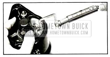
1953 Buick Checking Brush Spring Tension
When using the scale, apply a steady pull at 90 degree s to brush arm and note the scale reading at instant that brush arm is lifted off the brush. The reading should be between 24 and 32 ounces. If tension is not within these limits replace springs.
- New brushes must be seated to make good contact with armature, using a brush seating stone. This is a soft abrasive material which, when held against a revolving commutator, disintegrates so that particles are carried under the brushes and wear their contacting faces to the contour of the commutator in a few seconds. This operation may be performed on the bench if means are available for turning the armature, or it may be performed after generator is installed on engine. Blow all dust out of generator after the brushes are seated.
- Connect the armature wire (with black crossing tracers) to the “A” terminal of generator. This is the right hand terminal, farthest from engine. Connect the field wire (with black parallel tracers) to the left hand terminal.
- Before the engine is started, momentarily bridge between the “BAT” and “GEN” terminals of the generator regulator with a jumper wire or screwdriver. This allows a momentary surge of current from battery to generator, which correctly polarizes the generator with respect to the battery it is to charge.
10-26 TEST AND MINOR ADJUSTMENT OF 1953 BUICK GENERATOR REGULATOR ON CAR
Preliminary Instructions
The 1953 Buick generator regulator should be tested only when difficulty is experienced in keeping the battery charged, or when battery uses an excessive amount of water, which is usually caused by a high charging rate. Before testing the generator regulator make certain that the generator and circuit wiring are in good condition by performing the inspection and test given in paragraph 10-23.
The “Fixed Resistance” method of testing the operation and calibration of the generator regulator is recommended in preference to the “Variable Resistance” method which employs a variable resistance connected in series between the generator regulator and the car battery. The “Fixed Resistance” method uses a calibrated fixed resistance (1.5 ohms) in place of the car battery, therefore it eliminates the effect that battery condition may have on operation of the regulator units. All tests can be made without removing regulator cover, therefore proper regulator temperature can be maintained during tests.
The procedures given below in subparagraph c (using Sun Model VAT tester) and subparagraph d (using Allen Model 1202 tester) provide “Fixed Resistance” methods of testing the generator regulator.
After any test or replacement of regulator, the car generator must be polarized after all wires are connected but before engine is started. Failure to polarize generator may result in severe damage to the equipment since reversed polarity causes vibration, arcing and burning of the relay contact points. The generator may be readily polarized by momentarily bridging between the “BAT” and “GEN” terminals of regulator to cause a surge of current through the 1953 Buick generator.
Always make certain that rubber gasket is in proper position to seal regulator cover when installed. The gasket prevents entrance of dust, moisture, and oil vapors which might damage the regulator.
IMPORTANT: Mechanical checks and adjustments, such as air gap and point opening, must be made with battery disconnected from regulator and preferably with regulator removed from car.
Calibration of Test Voltmeter
The calibration of the test voltmeter should be frequently checked and should always be checked immediately following malhandling, sluggish movement of pointer, or when the meter has been dropped.
If the instrument being used does not have built-in provision for checking the calibration of the voltmeter and no commercial testing laboratory is available, the voltmeter may be calibrated against a specially prepared storage battery as follows:
- Select a satisfactory new 12-volt automotive storage battery and charge slowly (1 amp. per positive plate) until fully charged. Specific gravity of electrolyte should read between 1.260 and 1.280 in all cells. Allow battery to stand overnight at approximately 80°F. for stabilization of voltage. Battery terminal voltage will then be 12.8 volts. CAUTION: Do not use battery for calibration immediately after charging because battery voltage will be abnormally high for several hours.
- Check the test voltmeter against prepared battery and note reading. If meter does not read 12.8 volts, calculate the difference. Assume that error will be the same between 14 and 15 volts and allow this difference when using voltmeter to test and adjust 1953 Buick generator regulator. If voltmeter is found faulty it should be repaired at first opportunity.
The prepared calibrating battery also may be used to check an open circuit type battery testing meter by measuring the voltage of one cell, which will be 2.13 volts.
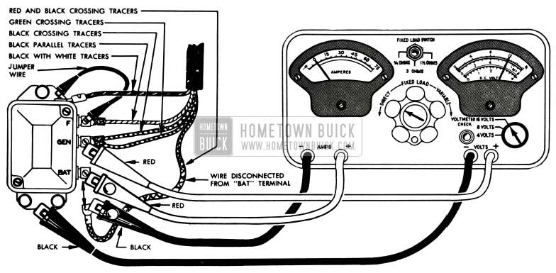
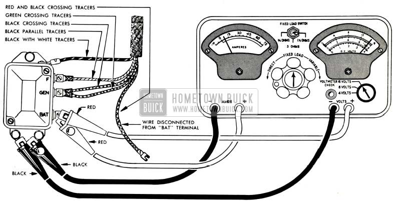
Test and Adjustment of 1953 Buick Generator Regulator Using Sun Volts Ampere Tester, Model VAT
The following procedure covers use of the Sun Volts Ampere Tester, Model VAT, in making tests and adjustments of the cutout relay, voltage regulator and current regulator in the order named. REGULATOR COVER MUST BE IN PLACE DURING ALL TESTS.
- Before using the Sun Volts Ampere Tester, Model VAT, check calibration of the voltmeter as follows:
- Turn Selector Switch to the “16 VOLTS” position.
- While looking squarely at voltmeter dial, press the “VOLTMETER CHECK” button and note whether the voltmeter needle aligns with the “SET” line. See figure 10-19. With check button depressed, the voltmeter is disconnected from any external circuit and is connected across an extremely accurate internal test cell which checks its calibration within the range required for testing the voltage regulator.
- If voltmeter needle does not exactly align with the “SET” line, hold “VOLTMETER CHECK” button depressed and adjust the Zero Corrector to bring voltmeter needle into exact alignment with “SET” line. See figure 10-13.
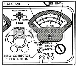
1953 Buick Voltmeter Calibration-Sun Model VAT
1953 Buick Cutout Relay Test Connections-Sun Tester
1953 Buick Generator Regulator Spring Tension Adjustments
CAUTION: Never close relay contacts by hand with battery connected to regulator because this will cause a damaging high current flow through regulator units.
- After cutout relay closing voltage is correctly adjusted, shut off engine. Remove jumper wire from “F” terminal of regulator but leave all tester leads connected for the following tests.
- Start engine and increase speed to approximately 1500 RPM. Run engine for at least 15 minutes to permit the regulator to reach operating temperature.
CAUTION: Since the voltage and current regulators are compensated for temperature, the following tests must be made with regulator at operating temperature to insure accurate results.
- When regulator reaches operating temperature, stop the engine. Turn Control Knob of tester to “FIXED LOAD” position and turn Fixed Load Switch to the “1 1/2 OHMS” position.
- Change the red voltmeter test clip from the “GEN” to the “BAT” terminal of regulator, where red ammeter test clip is already connected. Disconnect black ammeter test clip from car battery wire and connect it to good ground on regulator base plate. See figure 10-15. CAUTION: Do not allow disconnected car battery wire to touch metal.
1953 Buick Voltage and Current Regulator Test Connections-Sun Tester
- Turn tester control knob to the stop in “DIRECT” position and connect the black ammeter test clip to the disconnected car battery wire.
- Turn on headlights and set engine at speed which produces approximately 5 amperes output.
- Ground the “F” terminal of regulator and note ammeter reading. If output increases more than 2 amperes when “F” terminal is grounded, contact points are oxidized and should be cleaned (par. 10-27).
Adjust voltage regulator to obtain operating voltage of 14.5 DO NOT EXCEED 15 VOLTS UNDER ANY CIRCUMSTANCE. Adjust current regulator to obtain charging rate of 30 amperes.
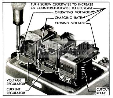
If adjusting screw is turned clockwise beyond normal range required for adjustment, the spring support may be bent so that it fails to return when pressure is relieved. If this happens, turn the screw counterclockwise until sufficient clearance exists between screw head and spring support, then bend spring support upward carefully until contact is made with screw head. Make final adjustment as described above.
- After adjustment of either regulator unit, install cover and gasket, bring regulator up to operating temperature and recheck calibrations starting with step 13 above.
- Upon completion of all tests and adjustments, disconnect regulator test equipment and reconnect battery wire to “BAT” terminal of regulator. Before starting engine, momentarily bridge between the “BAT” and “GEN” terminals with a screwdriver to polarize the 1953 Buick generator.
- Set engine idle speed at 450 RPM, then disconnect tachometer.
Test and Adjustment of 1953 Buick Generator Regulator Using Allen Volt-Ampere Tester, Model 1202
The following procedure covers use of the Allen Volt-Ampere Tester, Model 1202, in making tests and adjustments of the cutout relay, voltage regulator and current regulator in the order named. REGULATOR COVER MUST BE IN PLACE DURING ALL TESTS.
- Connect a reliable tachometer to indicate engine speed.
- Turn volt-ampere tester “SELECTOR” switch to “20V”, turn “GROUND” switch to “NEG”, and insert the BLUE plug of the 100 AMP. SHUNT into the “AMPS. ONLY” socket.
- Disconnect wire from regulator terminal marked “BAT” and attach flexible lead of 100 AMP. SHUNT to the “BAT” terminal of regulator. Attach the disconnected battery wire to opposite end of the SHUNT. See figure 10-17.
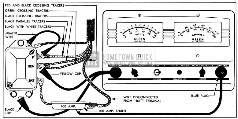
1953 Buick Cutout Relay Test Connections-Allen Tester
CAUTION: Never close relay contacts by hand with battery connected to regulator because this will cause a damaging high current flow through regulator units.
- After cutout relay closing voltage is correctly adjusted, shut off engine. Remove jumper wire from “F” terminal and disconnect 100 AMP. SHUNT from regulator, battery wire, and tester. Leave battery wire disconnected from regulator.
- Turn “SELECTOR” switch to “REG” position, leave “GROUND” switch at “NEG” position, and turn “REGULATOR” switch to “12V” position. Connect YELLOW clip of voltmeter lead to regulator terminal marked “BAT” and leave BLACK clip connected to ground on base plate of regulator. See figure 10-18.
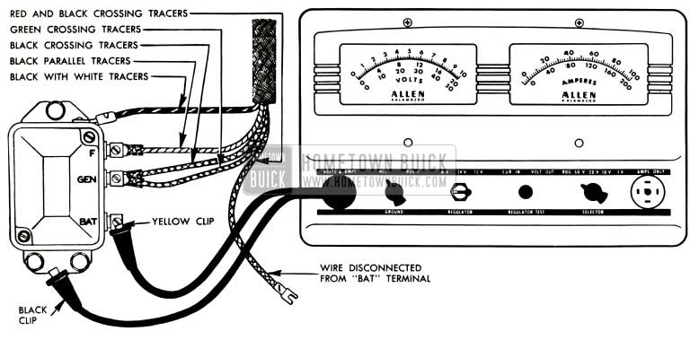
1953 Buick Voltage and Current Regulator Test Connections-Allen Tester
CAUTION: Since the voltage and current regulators are compensated for temperature, the following tests must be made with regulator at operating temperature to insure accurate results.
- Cycle the regulator by gradually reducing engine speed until cutout relay contacts open, then bring engine speed back to approximately 1500 RPM. The voltmeter reading will indicate the operating voltage, which will be between 14 and 15 if voltage regulator is properly adjusted. The ammeter will show a generator charging rate of 8 to 10 amperes. NOTE: If no ammeter reading is obtained, check the 14 ampere fuse in tester.
- Immediately following the voltage regulator test, proceed to the following current regulator test while the regulator is still at operating temperature.
- Increase engine speed to 2000 RPM, then depress the “REGULATOR TEST” button and note ammeter reading. Ammeter will read 27-33 amperes if current regulator is properly adjusted.
- Abnormal fluctuation of voltmeter or ammeter pointer during above test of voltage or current regulator indicates an oxidized condition of regulator contact points which would cause high resistance in generator field circuit and reduce generator output. In this case make the following test for oxidized contact points:
- Reconnect the 100 AMP. SHUNT as shown in figure 10-17, but do not connect the jumper wire nor the voltmeter lead (yellow and black clips).
- Turn on headlights and set engine at speed which produces approximately 5 amperes output.
- Ground the “F” terminal of regulator and note ammeter reading. If output increases more than 2 amperes when “F” terminal is grounded, contact points are oxidized and should be cleaned (par. 10-27).
- If either the voltage or current regulator did not operate within specified limits, remove regulator cover and adjust armature spring tension as required. Turn adjusting screw clockwise to increase operating voltage or charging rate; turn counterclockwise to decrease operating voltage or charging rate. See figure 10-16. The final setting must always be made by turning screw clockwise to increase voltage or charging rate-never by turning screw counterclockwise.
Adjust voltage regulator to obtain operating voltage of 14.5. DO NOT EXCEED 15 VOLTS UNDER ANY CIRCUMSTANCE. Adjust current regulator to obtain charging rate of 30 amperes.
If adjusting screw is turned clockwise beyond normal range required for adjustment, the spring support may be bent so that it fails to return when pressure is relieved. If this happens, turn the screw counterclockwise until sufficient clearance exists between screw head and spring support, then bend spring support upward carefully until contact is made with screw head. Make final adjustment as described above.
- After adjustment of either regulator unit, install cover and gasket, bring regulator up to operating temperature and recheck calibrations starting with step 13 above.
- Upon completion of all tests and adjustments, disconnect tester and reconnect battery wire to “BAT” terminal of regulator. Before starting engine, momentarily bridge between the “B.AT” and “GEN” terminals with a screwdriver to polarize the 1953 Buick generator.
- Set engine idle speed at 450 RPM, then disconnect tachometer.
10-27 1953 BUICK GENERATOR REGULATOR REPAIRS – ON BENCH
The contact points of a regulator will become oxidized and pitted after extended service and require cleaning. Contact points also may be burned because of faulty connections in the charging circuit, shorts or grounds in the 1953 Buick generator field circuit, or installation of a radio bypass condenser on the “F” terminal of generator or regulator.
The majority of regulator troubles arise from dirty and oxidized contact points, which cause a reduced generator output. Cleaning of contact points, or replacements if badly burned, followed by adjustment of air gap and spring tension will correct faulty regulator operation in most cases. Cleaning of points and adjustment of regulator should not be attempted with unit on the car; remove regulator so that this work can be done properly.
Cleaning Regulator Contact Points
Loosen the upper contact support mounting screws on voltage and current regulators and tilt support to one side so that each point can be cleaned separately without danger of bending the upper contact spring. Use a thin, fine-cut file on the crowned point on contact support, and use a spoon or riffler file to clean out the cavity which is usually formed in the flat contact point on the armature. See figure 10-19.
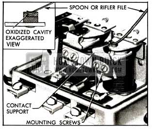
1953 Buick Cleaning Voltage Regulator Flat Contact Point
A flat file will not clean out this cavity. File just enough to remove oxidation. Never use emery cloth or sandpaper on contact points since particles of emery or sand left on points will cause them to arc and burn.
After contact supports are returned to position, reset air gaps (subpar. d, below).
Replacing Upper Contact Supports
If new upper contact supports are required or if supports have been removed, they should be installed as shown in figure 10-20.
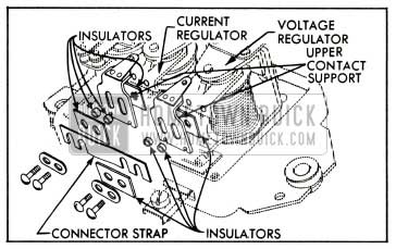
1953 Buick Relationship of Connector Strap, Insulators and Upper Contact Supports
Note that the connector strap is connected to voltage regulator contact support but” is insulated from the current regulator contact support. Note position of the flat and tubular insulators. After installation of contact supports, reset air gaps (subpar. d, below).
Adjustment of 1953 Buick Cutout Relay
The 1953 Buick cutout relay requires three checks and adjustment: Air gap, point opening and closing voltage.
- Place finger on armature directly above core and move armature down until contact points just close. If both sets of points do not close simultaneously, bend spring fingers so that they do. With points just closed, measure air gap between armature and center of core; gap should be .020″, measured with feeler gauge. Adjust air gap, if necessary, by loosening armature mounting screws and raising or lowering armature as required. Tighten screws securely and recheck air gap. See figure 10-21.
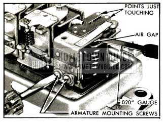
1953 Buick Adjustment of Cutout Relay Air Gap
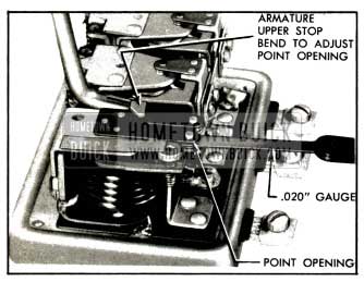
1953 Buick Adjustment of Cutout Relay Contact Point Openings
Adjustment of Voltage or Current Regulator
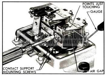
The voltage and current regulators require two checks and adjustment; air gap and voltage or current setting.
- Push armature down to the core and slowly release it until the contact points just touch, then measure air gap between armature and center of core, using feeler gauge. Air gap should be .075″.
- Adjust air gap on each unit, if necessary, by loosening contact support mounting screws and raising or lowering support as required. Be sure points are lined up when tightening screws, then recheck gap after adjustment. See figure 10-23.
1953 Buick Adjustment of Voltage Regulator Air Gap
Leave A Comment
You must be logged in to post a comment.