SECTION 3-H – 1953 BUICK STROMBERG 4-BARREL CARBURETOR
3-29 DESCRIPTION AND OPERATION OF 1953 BUICK STROMBERG 4-BARREL CARBURETOR
General Description
The 1953 Buick Stromberg Model 4AUV-267 carburetor used on the Series 70 engine is a 4-barrel Downdraft type which provides the advantages of a compound installation of two 2-barrel carburetors in one compact unit. See figure 3-79.
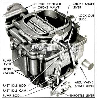
1953 Buick Stromberg 4-Barrel Carburetor
To aid description and the proper identification of parts the 1953 Buick Stromberg 4-barrel carburetor is considered to be divided into a primary section and a secondary section.
The primary section covers the 2-barrelled forward half of the carburetor assembly. This section is essentially a complete 2-barrel carburetor containing a float system, idle system with adjustable needle valves, main metering system, power system, and accelerating system. This section also includes an accelerator vacuum switch for starting the engine, and the automatic choke mechanism.
The secondary section covers the 2-barrelled rearward half of the carburetor assembly. This section is essentially a supplementary 2-barrel carburetor which cuts in to assist the primary section when a pre-determined car speed or engine load is reached. This section contains a float system, idle system with fixed jets (nonadjustable), and a main metering system. It has a separate set of throttle valves and a set of auxiliary valves, which are located in the barrels above the throttle valves.
The primary throttle valves are operated by the accelerator pedal and the connecting throttle linkage. The secondary throttle valves are operated by the primary throttle valve shaft through delayed action linkage which permits a pre-determined opening of the primary valves before the secondary valves start to open. Action of the linkage then causes both sets of throttle valves to reach the wide open position at the same time.
The accelerator vacuum switch, which is operated by a lever on the primary throttle valve shaft, is fully described in paragraph 10-30. The other systems of the carburetor are described in the following subparagraphs.
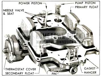
Operation of Float Systems
Each section of the 1953 Buick Stromberg 4-barrel carburetor has a separate and independent float system, consisting of a float chamber formed by a partition in the main body, a 2-pontoon float, needle valve seat and valve. Fuel enters the carburetor through a strainer in the inlet port in the secondary side of the air horn. From this point fuel flows to the separate float chambers through a horizontal passage in the air horn. See figure 3-80.
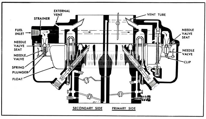
1953 Buick Primary and Secondary Float Systems
When the fuel reaches the prescribed level in each float chamber the float moves the needle valve against its seat to shut off flow of fuel. The needle valve in the primary section is connected to its float lever by a clip. The needle valve in the secondary section is spring loaded to prevent a build-up of fuel level in the float chamber due to bouncing of the float on bumpy roads. This feature is required because very little fuel is withdrawn from the secondary float chamber during part throttle operation.
The joint between the air horn and the main body is sealed by a gasket, and the float chambers are vented by passages which are calibrated to provide proper air pressure above the fuel under all operating conditions. These passages in the air horn lead into the throat of air horn, and to outside atmosphere. The exterior vents permit fumes to escape from float chambers when the engine is stopped after extremely hot operation.
Operation of Idle (Low Speed) Systems
Each barrel of the 1953 Buick Stromberg 4-barrel carburetor has a separate idle system but the general operation is identical in all barrels. The idle system in each barrel supplies fuel to the engine whenever the position of the throttle valve is such that suction is created at the idle discharge holes in the throttle body.
Suction on an idle discharge hole causes fuel in the float chamber to flow through the main metering jet and upward into the idle tube which meters the fuel. A bleed hole permits air to enter at the top of the idle tube so that a mixture of fuel and air passes down the tube and idle channel to the idle discharge holes. Additional air is drawn into the fuel-air mixture in the idle channel through the secondary air bleed which is in the throttle body in primary section and in the main body in secondary section. See figure 3-81.
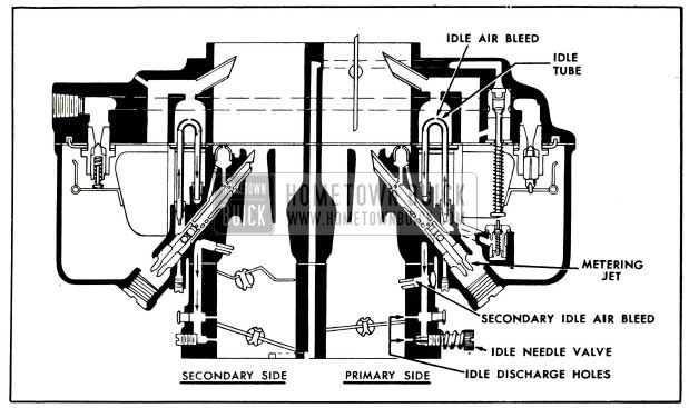
1953 Buick Primary and Secondary Idle Systems
When the throttle valve is closed, the fuel-air mixture is supplied through the lower idle discharge hole only, since the upper hole is above the valve and not affected by suction. As the throttle valve is opened suction is also placed on the upper idle discharge hole which then feeds additional fuel-air mixture into the engine. With continued opening of throttle valve the suction on the idle discharge holes tapers off until a point is reached where the idle system no longer supplies fuel-air mixture. Before this point is reached however, the main metering system has begun to supply fuel, as described later.
The secondary air bleeds in all barrels discharge a negligible quantity of fuel after the idle systems cease to operate, thereby keeping fuel immediately available in the idle channels at a point very near the idle discharge holes.
In the primary section, the quantity of fuel air mixture supplied through the lower idle discharge holes is controlled by the idle needle valves, which may be adjusted to provide smooth engine idle operation. In the secondary section, the quantity of fuel-air mixture is controlled by the fixed size of the discharge holes.
The secondary throttle valves remain closed during normal idle and intermediate speeds of the engine, until the primary throttle valves are opened to approximately 35-42 degrees. While the secondary valves are closed, fuel-air mixture is continuously delivered from the secondary lower idle discharge holes. As the secondary valves are opened additional fuel-air mixture is supplied through the upper idle discharge holes as previously described.
Operation of Main Metering Systems
Each barrel of the 1953 Buick Stromberg 4-barrel carburetor has a separate main metering system; however, the operation of all systems are identical. The main metering system in each barrel supplies fuel to the engine whenever the position of the throttle valve is such that the incoming air stream creates suction on the main discharge jet.
Air entering the barrel through the air horn passes through the primary and auxiliary venturi tubes which increase the velocity of the air and create a suction on the main discharge jet. This causes fuel to flow from the float chamber through the main metering jet into the main discharge jet. Air is drawn in through the high speed bleeder so that a mixture of fuel and air is discharged from the main discharge jet into the air stream passing through the auxiliary venturi in the barrel of the 1953 Buick Stromberg 4-barrel carburetor. See figure 3-82.
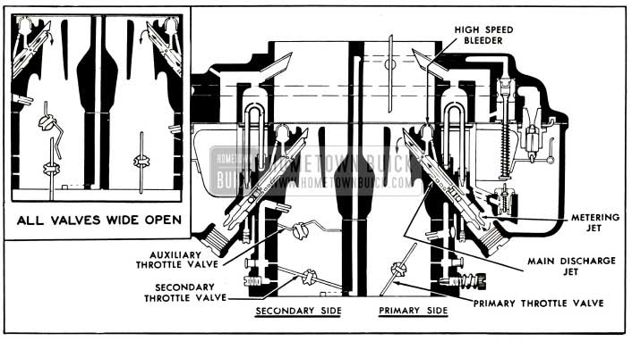
1953 Buick Primary and Secondary Main Metering Systems
The main discharge jet is designed so that if any vapor bubbles are formed in the hot gasoline the vapors will follow the outside channel around the main discharge jet and escape through the high speed bleeder instead of passing through the main discharge jet.
The main metering systems in the primary section control the flow of fuel during the intermediate or part throttle range of operation and up to approximately 80 MPH. The secondary throttle valves remain closed until the primary valves have opened approximately 35-42 degrees, after which they are opened proportionately so that all valves reach the wide open position at the same time. While the secondary throttle valves are closed, the auxiliary valves located above them are held closed by the weight on the auxiliary valve shaft lever (fig. 3-79); therefore there is not sufficient air flow through the barrels to operate the main metering systems in the secondary section.
When the secondary throttle valves are open and engine speed is at least 1200-1400 RPM, the resulting air flow through the secondary barrels forces the auxiliary valves open because their supporting shaft is located off-center in the barrels. When the auxiliary valves are open the main metering systems in the secondary section also supply fuel to the engine.
Operation of the Power System
For maximum power under load or extremely high speeds (85-90) MPH operation, a richer mixture is required than that necessary for normal throttle opening. This additional fuel is provided by one power system connected to the main metering systems in the primary section of the carburetor. See figure 3-82.
The power piston cylinder in the air horn of the 1953 Buick Stromberg 4-barrel carburetor is connected by a channel to the face of the mounting flange so it is subject to intake manifold vacuum. At part throttle position the vacuum is sufficient to hold the power piston in its “up” position against the tension of the piston spring. When the throttle valves are opened to a point where manifold vacuum drops to approximately 4 to 5 1/2 inches of mercury and additional fuel is required for satisfactory operation, the piston spring moves the power piston down to open the two power bypass jets. This allows additional fuel to enter the main discharge jets in the primary section through a channel which by-passes the metering jet. See figure 3-83.

1953 Buick Carburetor Power System
Operation of the Accelerating System
For smooth and rapid acceleration it is necessary to supply an extra quantity of fuel momentarily when the throttle is opened suddenly. This is accomplished by one accelerating pump piston which is directly connected to the primary throttle shaft lever by means of a rod and pump lever.
When the throttle is closed, the pump piston moves up and draws a supply of fuel from the float chamber through the inlet strainer, past the inlet ball check valve and into the pump cylinder. When the throttle is opened, the piston on its downward stroke exerts pressure on the fuel which closes the inlet check valve and opens the outlet check valve. A metered quantity of fuel is then discharged through the pump discharge nozzles into each barrel in the primary section of the 1953 Buick Stromberg 4-barrel carburetor. This occurs only momentarily during the accelerating period. The pump duration spring which is compressed by the downward movement of the piston against the resistance of the fuel provides a follow-up action so that the discharge carries out over a brief period of time. The spring loaded relief valve in the pump piston prevents an excessive build-up of pressure in the system when the throttle is snapped open suddenly, by providing an outlet through the piston for a small quantity of fuel when there is sufficient pressure to open the valve. See figure 3-84.
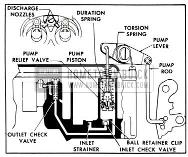
1953 Buick Accelerating System
When the desired speed is reached and the throttle is held in fixed position, the pressure on the fuel decreases sufficiently so that the outlet check valve closes and fuel ceases to discharge from pump nozzles. Thus a quantity of fuel is maintained in the channel adjacent to the outlet check valve where it is immediately available for future requirements.
Operation of the Automatic Choke
The automatic choke mechanism is contained in the primary section of the 1953 Buick Stromberg 4-barrel carburetor. It is identical with the choke mechanism used on the 2-barrel carburetor, which is described and illustrated in paragraph 3-25.
The secondary section does not have a choke valve in the air horn. In order to prevent air entering the 1953 Buick Stromberg 4-barrel carburetor through the secondary side during the engine warm-up period it is necessary to block the movement of the auxiliary valves by means of the lock-out slide shown in figure 3-79.
When the choke valve – is closed, the lock-out slide remains in the down position resting in a groove in the end of the auxiliary valve shaft. Movement of the auxiliary valves to an open position is then blocked by an ear on the lockout slide which extends into the line of travel of the auxiliary valve shaft lever. When the choke valve opens, the choke lever arm raises the lock-out slide until the ear on slide is clear of the valve shaft lever and the valves are no longer restricted to a closed position.
3-30 ADJUSTMENT OF FAST IDLE CAM, CHOKE UNLOADER, AND LOCK-OUT SLIDE
- Place a No. 41 drill between wall of air horn and the center of upper edge of choke valve, and hold valve firmly closed against the drill. See figure 3-85 (A).
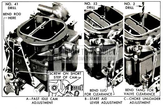
1953 Buick Stromberg Fast Idle Cam and Choke Unloader Adjustments
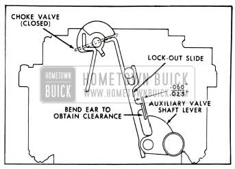
1953 Buick Lock-Out Slide Clearance With Choke Valve Closed
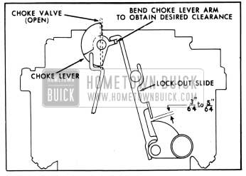
1953 Buick Lock-Out Slide Clearance With Choke Valve Open
3-31 DISASSEMBLY, CLEANING, INSPECTION OF 1953 BUICK STROMBERG 4-BARREL CARBURETOR
Disassembly of 1953 Buick Stromberg 4-barrel Carburetor
- Disconnect spring from secondary throttle shaft lever, then remove accelerator vacuum switch and gasket.
- Disconnect fast idle rod from choke shaft lever and disconnect pump rod from pump lever.
- Remove torsion spring, remove pump lever fulcrum screw (left hand thread), then disconnect pump lever from stem of accelerating pump piston.
- Remove all air horn screws, lift air horn far enough to remove the auxiliary valve lockout• slide, then carefully lift air horn straight up from main body to avoid damaging the float, pump piston, and vacuum power piston which are attached to air horn. Remove pump piston from air horn. See figure 3-88.
1953 Buick Parts on Stromberg Air Horn
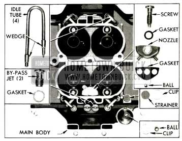
1953 Buick Parts in Main 4-Barrel Carburetor Body
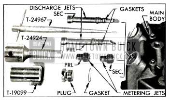
1953 Buick Main Metering and Discharge Jets and Tools
Remove screws and slide the valves out of shafts.
- Disconnect control rod from secondary throttle shaft lever and remove shaft from throttle body.
- Remove nut, lockwasher, switch lever, and loose lever from end of shaft, then remove primary throttle lever and shaft assemblies from throttle body.
Cleaning and Inspection of Parts
The procedure for cleaning and inspection of parts is the same as the procedure given for the 2-barrel carburetor in paragraph 3-27 (b, c), except that the idle tubes are cleaned by a different method.
Under normal service conditions it should not be necessary to remove the idle tubes because the small plugs in the underside of main body may be removed for thorough cleaning of the idle tubes while installed in main body.
If it becomes necessary to remove an idle tube for any reason, pry it out with a screwdriver placed under the loop, being sure to place a piece of wood under point of screwdriver to avoid marring the surface of main body. Discard the old parts and install a new tube with wedges as follows:
- Place Tool T-25525 on top surface of main body with flat sides vertical and place the idle tube with wedges in position over the tool. See figure 3-91.
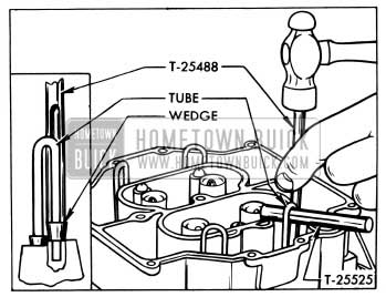
1953 Buick Installing Idle Tube
Make certain that the small diameter end of idle tube is in the hole directly above the main discharge jet passage.
3-32 ASSEMBLY AND ADJUSTMENT OF 1953 BUICK STROMBERG 4-BARREL CARBURETOR
Assembly of 1953 Buick Stromberg 4-barrel Carburetor
When assembling the 1953 Buick Stromberg 4-barrel carburetor use all new gaskets and any additional new parts found to be necessary during inspection. Calibrated parts must be as specified for carburetor CODE number.
- Install primary throttle lever and shaft assembly in throttle body, then install throttle control loose lever, switch lever, lockwasher, and nut as shown in figure 3-92.
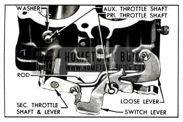
1953 Buick Throttle, Shaft Levers and Control Rod
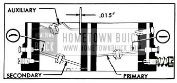
1953 Buick Installation of Throttle Valves Schematic
Loosely install new valve screws and carefully align the valves with the scribe marks previously made along edges of valve shaft, then tighten screws.
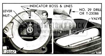
1953 Buick Choke Valve and Vacuum Piston Adjustment
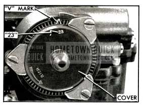
1953 Buick Choke Thermostat Standard Setting
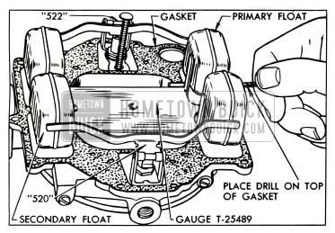
1953 Buick Carburetor Float Adjustment
Lightly tap fulcrum pin to seat serrated end into hanger leg. Make certain that float moves freely in hanger.
- Place Float Setting Gauge T-25489 flat and secure on top of the air horn gasket, with bosses on gauge in the two holes along centerline of air horn. See figure 3-96.
- Using Tool T-24733 (or pliers) bend float lever as required to obtain 3/64″ clearance between center of each primary float pontoon and the gasket surface, using a No. 56 twist drill as a clearance gauge. See figure 3-96.
- Bend the secondary float lever as required to obtain 1/32″ clearance between air horn gasket and center of each float pontoon, using a No. 68 drill as a gauge.
- Bend float levers as required so that the sides of all float pontoons are parallel with, and just cl ear of, the uprights of Gauge T-25489. Floats must move freely with gauge in place, and float height setting must not be changed by this adjustment.
Adjustment of Primary and Secondary Throttle Valves
It is important that the opening of the secondary throttle valves be properly coordinated with the opening of the primary throttle valves. This should be checked as follows:
- Turn primary throttle valves to wide open position, where they must be parallel with walls of barrel. The secondary throttle valves should likewise be wide open and the inner end of secondary throttle shaft lever should bear against the stop boss on throttle body.
- If the primary valves cannot be fully opened because the secondary shaft lever strikes the stop boss too early, or the secondary valves do not reach the wide open position, an adjustment of the vacuum switch lever is necessary.
- Hold the switch lever by applying a suitable wrench to the flat surface below the loose lever, then bend the curved end of switch lever up or down with pliers as required to obtain the results specified in step 1. See figure 3-97.
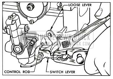
1953 Buick Adjustment of Secondary Throttle Linkage
Leave A Comment
You must be logged in to post a comment.