NEW COLOR COMBINATIONS
In the near future, nine new color combinations will be offered on 1951 models. On approximately the same date, five current combinations will be cancelled, three of which are replaced by new colors. The cancelled combinations are as follows:
Combination Number- Color
04 – Geneva Green
06 – Olympic Blue
08 – Sharon Green
12 – Sky Grey – Upper; Olympic Blue – Lower
14 – Sky Grey – Upper; Sharon Green – Lower
Following are the added combinations, and replacements where applicable:
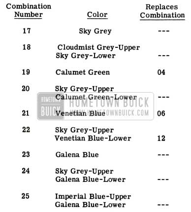
1951 Buick Color Combinations Replacements
All of the new combinations will carry the Dante Red wheel option.
The following new colors are used in the combinations listed above:
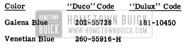
1951 Buick Duco and Dulux Paint Codes
This information is intended for refinish personnel only and does not constitute an indication that all new combinations are available on immediate order.
1951 COLOR COMBINATIONS
The following “Dulux” matches have been established for Venetian Blue and Calumet Green:
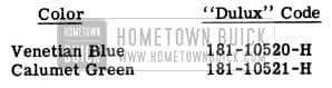
1951 Buick Dulux Paint Codes
Please record these new matches in the space that was provided in BPS 2.301, page 96.
In addition to the nine new color combinations described in BPS 2.301, two more combinations have been released for production as follows:
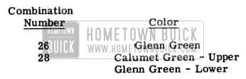
1951 Buick New Colors
The new Glenn Green combination has the following refinish code numbers:
1951 Buick New Glenn Green Paint Numbers
CHANGE IN PAINT POLICY
The following is a reprint of Special Service Letter Dealer No. 97, dated June 19, 1951:
Subject: Paint On New Cars
A very important responsibility of Buick Service Managers is to see that every new car is delivered to the purchaser in as near perfect condition as possible.
A recent survey of owner complaints indicates that a number of new car purchasers are not completely satisfied with the condition of the paint on their new cars when delivered to them. Many owners state that they are told that the paint will be taken care of at the 1,000 or 2,000 mile inspection.
An analysis of AFA’s covering thin paint indicates that almost 60% of the refinishing jobs are performed on cars after delivery. This would indicate that the purchasers of these cars were not completely satisfied with the condition of the paint on their cars at the time of delivery, and, therefore lost much of their new car enthusiasm.
Another undesirable feature of this is that once the owner finds a spot where the paint is thin or rubbed through, he immediately closely inspects the entire automobile to find out how many more places he can find, and he usually finds them or at least thinks he has found more.
In checking this with a number of dealer Service Managers we are told that the reason new car refinishing work is not done before delivery is because of the delay involved in securing Zone Office approval, in accordance with Special Dealer Service Letter No. 74, dated November 16, 1949, which covers our paint policy and also listed on page 10, Paragraph 1, of the Buick Service Policy Administration Manual.
Therefore, effective immediately it will no longer be necessary to secure Zone Office approval to correct unsatisfactory paint on individual panels, if that work is done on new cars before they are delivered to the purchaser.
If it is not done before delivery, Zone Office approval is necessary before proceeding with the work.
This change in policy applies only to individual panel refinishing. In cases where it is felt that the entire car requires refinishing, Zone Office approval must be obtained.
To put this policy in effect, we suggest that every dealer wash and inspect each new car as soon as it is received and then refinish any panels or portions of panels not found up to standard.
AFA’s will not be accepted for the following conditions:
- Removal of minor surface blemishes or scratches in the finish which can be polished out.
- Brush touch-up work found necessary.
- Rubbed through spots caused by careless workmanship in the dealership while the car is being polished for delivery. These are the dealer’s responsibility.
- Damage after delivery caused by flying gravel, excessive polishing or lack of care by the owner.
AFA’s submitted for paint work should give a clear description of the conditions which required the refinishing. If spots on a panel actually are not covered sufficiently and primer is showing thru, the description should be “thin paint” and the exact location given on the AFA.
If the paint appears to have been put on over dirty metal, that information should be shown on the AFA.
It is difficult for anyone to justify a paint AFA where the description indicates the paint was thin and the car has been driven 4,000 miles. If the paint was thin when the car left the factory, it should have been taken care of before the car was delivered.
The intent of this change in policy is to aid all dealers in delivering new cars to purchasers in tip-top condition, and prevent possible complaints and dissatisfaction. Strict adherence to this policy will accomplish that purpose.
SILICONE POLISHES
The following information has been received from the Refinish Sales Department, E. I. Du Pont De Nemours & Co. (Inc.) and should be of vital interest to all Service personnel connected with body polishing and refinishing:
Polishes and waxes, both spray and wipe-on types, which contain silicone oils are extremely difficult to remove completely. They even leave a residue in the cleaning rags which contaminates any surface on which these rags are used. Therefore, drastic measures are necessary to avoid “fish eyes,” “craters” and spots, as shown in Figure 56, before applying new lacquer or enamel finishes.
1951 Buick Silicone Polishes
- Apply Du Pont’ ‘Prep-Sol” on silicone polished surfaces -wipe off with clean rags before the “Prep-Sol” has a chance to dry. Change rags frequently. Do not re-use these rags any place in the shop as they will cause “fish eyes” etc., if residue from them gets on any surface which is being refinished.
- Wet sand with 1320 paper, using DULUX T-3812 Thinner.
- Clean again with “Prep-Sol” using the same procedure and precautions as outlined in’ ‘1”.
We cannot over-emphasize the importance of keeping the shop clean and free from the silicone on rags, clothing or spray equipment. Never use a gun to spray refinishing materials after it has been used to apply silicone polishes, and do not do refinishing work near an area where silicone or wax polishes are applied.
To find out whether silicone polishes have been used on a car that is to be refinished, test first. This can be done by spraying DULUX Enamel (any color) on a small vertical area of the car to be refinished. If these polishes have been used on the car, the “fish eyes” or “craters” will appear in the DULUX finish before it sets up. The DULUX can then be wiped off with T-3812 Thinner.
MAINTENANCE OF NEW CHROME
LATE 1951 ALL SERIES
Material restrictions imposed by the National Defense Program have made it necessary to change the plating process used on some of the chrome parts used on current cars. Since there is no simple method of identifying which process has been used, our instructions and recommendations regarding care will be such that they apply to all types of chrome. The new processes, however, are protected by a clear baked enamel and in view of this it is extremely important that abrasive materials of any type for cleaning or polishing be avoided. When the enamel has been scratched, the protection is gone. This is the reason we are placing the precautions in the glove compartment of each new car starting approximately September 15th. (Sample attached to this BPS) Special care is required and special instructions regarding refinishing are absolutely necessary. Repairs to scratches or abrasions that occur on parts having the protective coating of enamel must be performed within a reasonably short period of time to prevent further deterioration to the finish.
Contrary to our previous instructions in BPS ‘s relative to buffing the protective wax coating being used on bumpers we now recommend that it be completely removed by the dealer before the car is delivered. Our reason for this change in recommendation is because of the appearance of the wax even after buffing. It may be removed with a mild soap or detergent and warm water.
At the time this bulletin is written there are no substitute finishes being used on the exterior brightwork of the car, however it will be impossible for us to tell exactly when and what parts will be changed and we wanted all concerned to have the necessary information.
We have run extensive tests on Buick chrome Preservative, Group 8.800, Part 981164, and are satisfied that it will do an excellent job for our owners in prolonging the lustre of chrome parts and retarding corrosion. The preservative is packaged in pressurized cans and is simply sprayed on and then wiped off with a cloth. It is recommended that all exterior brightwork be given an application of Buick Chrome Preservative once a month. Light washings with water and mud detergents such as DuPont Car Wash will not completely remove the preservative and a once-a month application will provide excellent protection in spite of repeated washings. The preservative is applied after all brightwork is thoroughly washed, using no abrasives. The dispenser is held approximately one foot from surface and is sprayed with long, even strokes. After the oil film has set five minutes, the surface should be thoroughly wiped with a clean, soft cloth. Note: Buick Chrome Preservative is not harmful to painted surfaces.
The clear enamel finish which may eventually be used on certain parts is naturally subject to scratches and abrasions. For this reason the following refinishing procedure is recommended and can be used for all chrome parts regardless of the original plating process used. In addition it is imperative that all service department personnel be informed that chrome parts be properly masked when doing any paint repair spraying or body refinishing. Any cleaner used to remove over-spray will also remove the enamel from the chrome.
Refinishing Procedure
Repairing any damaged or scratched sections of these plated parts through the use of abrasives is extremely hazardous because of the possibility of scratching the chrome or exposing the copper plating beneath the chrome. The use of emery cloth, harsh rubbing compounds, or sandpaper should be avoided. No attempt should be made to remove small scratches or mars. Should the repair spot be large enough that the enamel has been broken through in a large enough area to require feathering the edges to make a presentable repair, the edges can be feathered with a small amount of Rotton Stone (cake or powder) on a wet cloth or felt. Care should be taken to avoid enlarging the spot to be repaired any more than necessary.
Prior to applying the refinishing material, the damaged section should be cleaned with naptha or commercial cleaner such as “Prep-Sol”.
The refinishing material can be either sprayed or brushed on the surface. Apply two brushing coats or two spray coats with suitable drying time between coats.
The recommended refinishing material is DuPont #1234 Clear, available at all local DuPont jobbers.
“Rotton Stone” is similar to pumice but much milder and is available at most drug stores.
MODEL 72R FRONT SEAT
Some complaints are being received relative to insufficient front seat cushion depth on the 1951 Model 72R.
Although this model was designed to provide the same cushion depth as other 1951 jobs, some of the early production cars had the upholstery on the cushion installed too tight, causing an extreme radius at the front edge. This condition can be relieved by loosening the front edge of the upholstery and moving the Foamtex rubber pad forward to a position 1/2″ ahead of the border wire on the spring. When refastening the trim, it is necessary to use longer clips and to avoid pulling the cloth too tight.
Additional front seat comfort can be obtained by changing the angle of the front seat back, as outlined on page 70. Figure 59.
SEAT ADJUSTER KNOB
1951 ALL SERIES
Due to critical material restrictions, the front seat adjuster knob on all 1951 models is now fabricated from plastic in place of the die cast knob formerly used. When installing this knob, the set screw should be turned until snug and then tightened 1/4 add1tlonal turn. Excessive tightening may crack the plastic and cause the knob to work loose.
SEAT TRIM DAMAGE
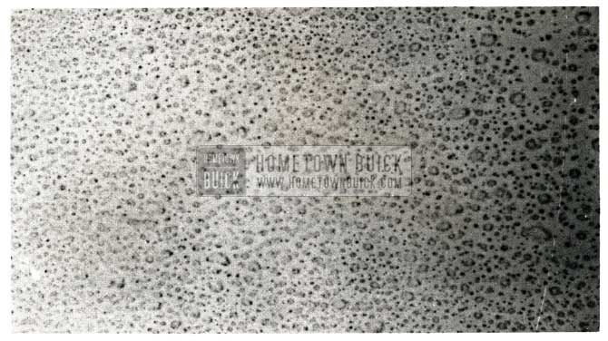
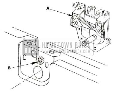
Some reports have been received concerning front seat cushion trim damage, at the seat back hinge arm cutout, on the 1951 Model 480. This damage occurs because the cushion trim material is stretched excessively by the hinge arm when the seat back is in the full forward position. If this condition is encountered, it should be corrected as follows:
- Move the right ”seat back” to the full forward position and determine if the cushion trim is being damaged by the seat back hinge arm shown in Figure 57.
1951 Buick Seat Trim Damage
- Remove the seat side trim panel at the right side of the front seat cushion.
- Remove the retaining clip located on the pivot shaft at the right side of the seat back and disengage this side from the pivot shaft.
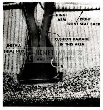
- Move the front seat assembly to the full rear position to gain clearance, and remove the cotter pin at “A” in Figure 57 from the end of the pivot pin. Push the pivot pin far enough to the left to remove the right seat back from the seat assembly.
1951 Buick Right Front Seat Back
Drill and countersink two holes in the shim.
END GATE LOCK RATTLES
1950-51 MODELS 59-79
We have received a few complaints of rattles in the Estate Wagon end gate area caused by the interior lock handles striking the recessed escutcheons.
This condition has been corrected in production by installing a rubber bushing over the lever handles. The same correction can be made in the field by installing one each Group 4.019, Part No. 1319010 Transmission Shift Lever Insulators over the handles so that the levers will be held snug and cannot contact the escutcheons.
FRONT SEAT ANGLE
Any complaints received in the field, to the effect that the front seat back on 1951 Model 72R sedans is installed at an uncomfortable angle, can be handled by the procedure shown in Figure 59.
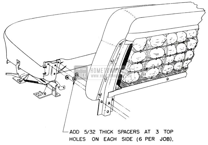
1951 Buick Front Seat Angle
Addition of the designated spacers will tilt the top of the seatback to a more comfortable position.
Fisher Body Division has made this modification in production on all ’72R bodies, beginning a proximately February 12, 1951.
CONVERTIBLE TRIM PANELS
The Folding Top Compartment Side Trim Panels used on the 1951-56C and 76C are identical with the 1950 parts, except for the location of moulding attaching holes.
We anticipate that the 1950 panels will become difficult to obtain and, for that reason, they will be replaced by current model parts as follows:
CONVERTIBLE TOP DAMAGE
1951 SERIES 50-70 CONVERTIBLES
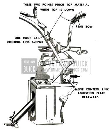
We have received a few reports of damage to convertible top material, in the rear quarter area, on Series 50 and 70 jobs. When this condition occurs, the top linkage should be inspected and corrected as follows:
When dealers receive one of the 1951 panels for use on a 1950 car, it will be necessary to drill 23 slots 1/8″ x 1/2″ long to allow molding installation. These slots can be located by reference to the panel on the opposite side of the car.
- Fully lower the top and carefully check with the fingers to determine if the side roof rail control link support rests against the rear bow and pinches the top material between the two points indicated in Figure 60.
1951 Buick Convertible Top Damage Repair
If this condition exists, the control link adjusting plate must be moved REARWARD to provide clearance.
After moving the adjusting plate, check the clearance to make sure the top material will not be pinched.
- Check the side roof rail control link support for any sharp burrs that could catch the top material.
If there are any burrs, they must be removed and the bare spots touched up with paint to match the top linkage.
HYDRO-LECTRIC FLUIDS
ALL HYDRO-LECTRIC STYLES
The following is a list of the hydraulic fluids which have been approved for use in all Hydro-Lectric equipped Fisher Bodies:
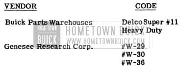
1951 Buick Hydro-Lectric Fluids
Any of the above fluids can be safely added to a hydraulic system which already contains one of the other approved fluids. Genesee Research Corp. fluids #W-29 and #W-30 can be used if they are presently available, however, we have been advised they are no longer being supplied by the vendor.
HARD CLOSING TOPS
1951 MODEL 46C
Some trouble has been encountered with hard closing tops on early production 1951 Model 46C Convertibles. This condition can be caused by a loose front roof rail locking rod or by the front roof rail weatherstrip offering high compression resistance. Either or both of the following corrections may be required when “hard closing top” complaints are received:
- FRONT ROOF RAIL LOCKING ROD RETAINER REWORK PROCEDURE
- Remove the end clips located at each end of the “Hide-em” binding.
- Unfold the “hide-em” binding to expose the trim tacks and remove tacks and binding at the front corners of the roof rail.
- Remove the trim tacks along the front edge of the top material and turn the top material back at each corner to gain access to the lubrication hole shown in Figure 61.
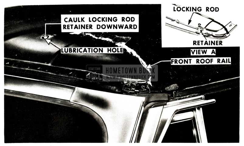
1951 Buick Convertible Top Lubrication Hole
(Lubrication holes are sealed with waterproof tape.)
- FRONT ROOF RAIL WEATHERSTRIP REWORK
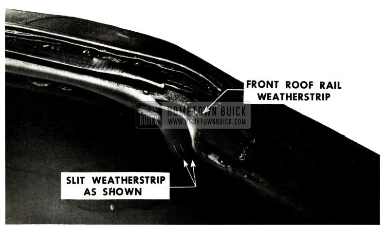
1951 Buick Front Roof Rail Weatherstrip
Both these rework operations have been incorporated in current production.
FOLDING TOP LIFT LINK
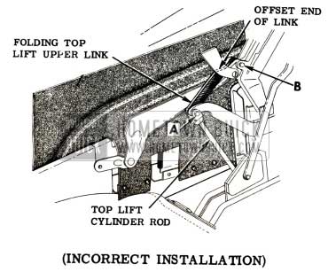
We have been advised that some Model 46C (up to Body No. G 325) convertible top assemblies were assembled with the ”folding top lift upper link” in the reversed position. The offset end of the link was installed toward the front (see Figure 63 instead of at the top lift cylinder yoke.
1951 Buick Folding Top Lift Link
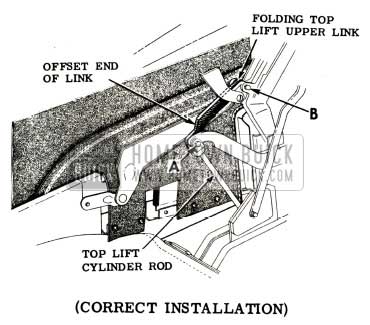
This condition causes the top linkage to be shifted outboard resulting in damage to the top material and the rear quarter body structure when the top is operated. It should be corrected, if encountered, by removing the link and reinstalling with the offset at the lift cylinder yoke end as follows:
- Raise the top and lock it in position.
- Remove the pivot bolts “A” and “B”.
- Remove the folding top lift upper link and install it correctly with the offset end in the lift cylinder yoke as shown in Figure 64.
1951 Buick Folding Top Lift Link Correction
DOW CORNING NO. 4 COMPOUND
ALL YEARS AND MODELS
We have recently determined that Dow Corning No. 4 Compound is superior to materials used in the past as a rubber lubricant. This compound is a translucent grease-like material having a consistency similar to vaseline. It is very moisture resistant, chemically inert so that it has no swelling effect on rubber and does not change appreciably in consistency through a temperature range of minus 65°F to over plus 400°F.
DC No. 4 Compound should find many uses in a dealership particularly as a lubricant for hood lacing, hood bumpers and other rubber parts that produce an annoying squeak when not lubricated. It is also very effective as a weatherstrip freeze preventive around door and trunk lid openings and it will delay checking and cracking of all exposed weatherstrip.
A light coating of DC No. 4 Compound is all that is required and in most cases one application is sufficient for an entire season. It is insoluble in water, lubricating oil and anti -freeze liquids but can be readily dissolved by common solvents such as gasoline, benzol and carbon tetrachloride.
We believe that an eight ounce collapsible tube is the handiest size for average dealership use and it can be obtained in various quantities at the following prices:
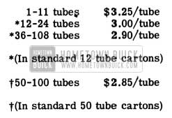
1951 Buick Dow Corning Prices
All prices quoted are net cash, 30 days; freight prepaid and allowed.
Order for Dow Corning No. 4 Compound can be placed through any of the following Dow Corning warehouses:
Dow Corning Corporation
1343 Spring Street, N. W.
Atlanta, Georgia
Dow Corning Corporation
600 Fifth Avenue
New York, N.Y.
Dow Corning Corporation
1514 South Hope Street
Los Angeles 15, California
Dow Corning Corporation
2722 Taylor Street
Dallas 1, Texas
Dow Corning Corporation
P.O. Box 592
Midland, Michigan
HYDRAULIC LIFT “WHISTLE”
ALL HYDRO-LECTRIC STYLES
Occasionally we receive complaints of an excessively loud “whistling” noise in Hydro-Lectric lift cylinders when windows are lowered. This noise is caused by friction in the lift cylinder assemblies and has now been corrected in production by use of a hydraulic fluid having greater lubricating characteristics.
When this condition is encountered in the field, the Hydro-Lectric system should be drained and refilled with Delco Super No. 11 hydraulic fluid which also has the improved lubricating characteristics. After filling, the noisy cylinder should be operated through five or six cycles to enable the fluid to saturate the packing and gaskets in the lift cylinder. This treatment will usually eliminate the “whistling” noise but, in some cases, more than six ”break-in” cycles may be required.
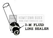
HYDRAULIC LINE SEALER
ALL HYDRO-LECTRIC STYLES
All Hydro-Lectric couplings and fittings are now sealed in production with”3-M Fluid Line Sealer” distributed by the Minnesota Mining and Manufacturing Company.
This improved sealer is available in 1/4 pint glass containers for service use in the field. For best results the sealer should be used as follows:
1951 Buick Hydraulic Line Sealer
Apply on the male pipe thread from end of fitting to the hexagon portion. Brush sealer completely around threaded portion except for first thread. Assembly should be made while sealer is still wet.
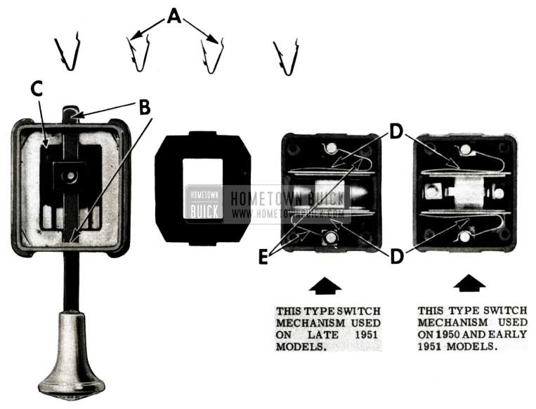
HYDRO-LECTRIC MOTORS
ALL 1951 CONVERTIBLES
We have encountered a few cases of burned-out Hydro-Lectric motors on 1951 Convertibles, apparently caused by continued current supply to the motors after the top was fully opened or closed. This condition is caused by a “bind” in the folding top control switch which prevents the switch push rod from breaking the electric circuit. The trouble can be corrected, in most cases, by using the following procedure:
- Remove the folding top control switch from the instrument panel.
- Disconnect the wires from the switch terminals.
- Disassemble the switch by removing the four clips “A” shown in Figure 65.
1951 Buick Hydro-Lectric Convertible Top Switch
CONDITION (A): The control rod is binding in the die cast housing at’ ‘B” and does not allow free back and forth movement of the rod.
CORRECTION: Lift the plastic knob “C” from the control rod, remove the control rod from the die cast housing, and file out the square hole in the housing to provide free sliding clearance to the rod.
CONDITION (B): The small manufacturers number and letter symbols, molded into the bottom of the bakelite housing of the switch at location “D” interferes with the sliding action of the copper switch plates.
CORRECTION: Remove the copper switch plates and springs and smooth off the bottom of the bakelite case by scraping the surface.
CONDITION (C): The “BAT” terminal of the switch is loose in the bakelite housing which allows the contact stud of the terminal to remain in contact with the center copper switch plate after the knob has returned to neutral.
CORRECTION: Tighten the lock nut for the “BAT” terminal stud of the switch.
CONDITION (D): The springs “E” are not resilient enough to return the switch back to neutral.
CORRECTION: Replace the entire control switch assembly.
- Reassemble the switch, reconnect the wires, install the switch to the instrument panel and check operation.
HYDRO-LECTRIC SERVICE
1946-1951 GENERAL MOTORS CARS
- VENTED SYSTEM FOR CONVERTIBLE TOP OPERATION ONLY
Hydro-Lectric systems used on Fisher bodies from 1946 through 1951 are of two basic types:
- THE VENTED SYSTEM which requires a periodic fluid change.
- THE SEALED SYSTEM which does not require periodic fluid changes.
The vented system, which is used on all Buick models, must be drained and refilled with approved fluid at least once a year, preferably in the Fall, in order to avoid moisture and sludge accumulation with resultant parts failures.
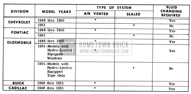
1951 Buick Hydro-Lectric Systems on GM Cars
The chart (Figure 66) ,showing the type of system used on all 1946 through 1951 General Motors cars is intended to assist dealers in servicing used cars and GM makes which may come into their shops for service. All cars with the vented system should be serviced with one of the approved Hydro-Lectric fluids listed.
- Remove and empty the fluid reservoir.
- Reinstall empty fluid reservoir.
- Move top up and down by hand through its complete raising and lowering cycle.
- Again remove reservoir. Empty old fluid, clean, refill with new fluid and reinstall.
- Operate top through two complete cycles.
- Again remove reservoir, add additional fluid to bring to proper fluid level as indicated on reservoir and reinstall.
- VENTED SYSTEM FOR CONVERTIBLE STYLES HAVING HYDRO-LECTRIC EQUIP – PED WINDOWS AND FRONT SEAT
- Lower windows and move front seat rearward.
- Remove reservoir, empty, and reinstall empty reservoir.
- Move top up and down by hand through its complete raising and lowering cycle.
- Remove reservoir, empty, clean thoroughly, refill with fresh fluid and reinstall.
- Operate the top through two complete up and down cycles.
- Remove reservoir and add sufficient fluid to bring to proper fluid level, then reinstall.
- Check the operation of all windows and front seat.
- VENTED SYSTEM FOR CLOSEDAND HARDTOP STYLES
- Lower windows and move front seat rearward.
- Remove and empty reservoir and clean thoroughly.
- Fill reservoir to specified level and reinstall.
- Check operation of windows and front seat.
- SEALED SYSTEM FORCONVERTIBLE TOPS The sealed system fluid should be checked periodically through the filler cap on top of reservoir and additional fluid added as required.
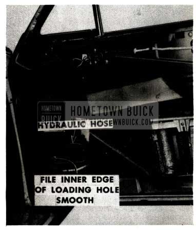
HYDRO-LECTRIC HOSE DAMAGE
Inoperative or slow operating hydraulic front door windows will result from loss of hydraulic fluid due to cut hydraulic hoses in the front doors. This condition is caused by the hose rubbing against a sharp edge of the door inner panel loading hole and can be easily corrected as follows:
- Remove the door trim pad and the small loading hole cover plate.
- File the inner edge of the loading hole, shown in Figure 67, to remove the sharp edges.
1951 Buick Hydro-Lectric Hydraulic Hose Damage
HYDRAULIC TUBING PROTECTION
1951 HYDRO-LECTRIC STYLES
Hydraulic tubing running along the floor pan is now being given a waterproof coating of sealer, in production, to protect against moisture, condensation and corrosion. In the event this hydraulic tubing is removed for service, the following procedure should be used when re-installation is made:
- Apply 3-M Autobody Sealer to the surface of the floor pan where the hydraulic tubing is to be installed (see “1” in Figure 68).
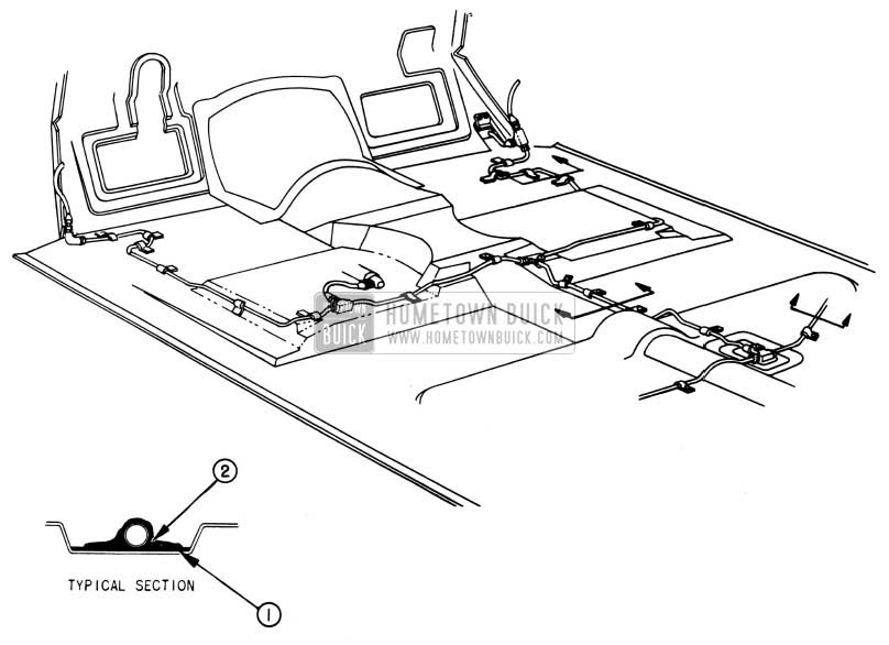
1951 Buick Hydro-Lectric Tubing Protection in Floor
HYDRAULIC LIFT SUPPORT
1951 HYDRO-LECTRIC STYLES
The door window hydraulic lift support used on 1951 hydraulic styles, has been redesigned to eliminate rattles at the support. A few reports have been received concerning insufficient downward travel of the door glass, due to this new support binding on the hydraulic lift side member (See Figure 69).
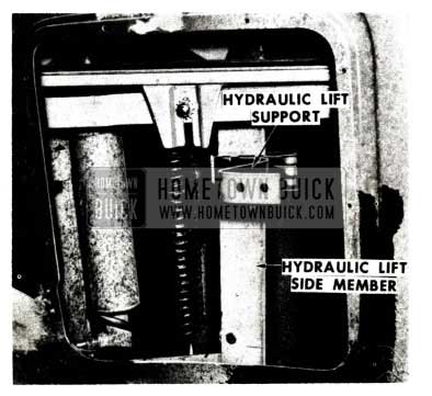
1951 Buick Hydraulic Lift Support
The three possible types of lift support bind, and their correction, are as follows:
- Yoke of support too tight. The yoke should be spread, as indicated in Figure 70, to permit full sideward travel of the side member.
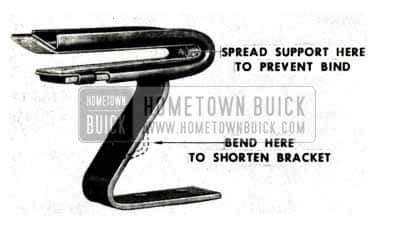
1951 Buick Hydraulic Lift Support Spred
Do not open the yoke excessively or rattles will result.
SERVICE DOOR ASSEMBLIES
Front Door Assemblies, Group 10.351, Part Nos. 4183591 ‘(Right) and 4183592 (Left) carried for service on 1951 Models 56C, 56R, 76C and 76R, are special service doors and will replace doors currently serviced for 1950 Models 56C, 56R, 75R, 76C and 76R when present stocks are exhausted.
These service doors can be used on either the mechanical or hydraulic window lift types.
When installing the above mentioned doors on 1950 – 56C, 76C or 76R jobs with hydraulic window lifts, it will also be necessary to install a Group 10.778, Part No. 4595268, Hydraulic Lift Door Window Support, using three #1/4-20 x 7/16 hex-head cap screws as used on 1951 models. It is not practical to remove and reuse the welded supports as supplied with original 1950 doors.
When replacing a door which did not include door window lower reveal moulding retainers, use two Group 10.707, Part No. 4591864, retainers at the rear of each door.
DOOR LOCK FREEZE CAUTION
1951 ALL SERIES
In order to avoid frozen door lock cylinders when cold weather arrives, it is essential to avoid over-lubrication of lock cylinders at this time. The door lock cylinders should be lubricated with one or two drops of fine oil at 6 month or yearly intervals. Excessive application of oil or too frequent lubrication will wash away the special wax treatment applied during manufacture and make the cylinders susceptible to freezing.
In the event that freezing is encountered with over-lubricated locks, the paraffin treatment should be applied.
DOOR VENT REGULATOR SEAL
1951 ALL SERIES
A new front door ventilator regulator weathersealing operation has been in incorporated in production on all 1951 models, coincident with use of a stamped regulator assembly. The purpose of the seal is to divert any water that enters the body at the ventilator pivot down between the door panels for drainage and thus prevent water stains on door trim pads.
This operation should be performed on these models when service operations at the front door ventilator are required. Before reinstalling the regulator apply a 3/16″ bead of 3-M Body Caulking Compound as shown at “A” in Figure 71 and seal the clearance hole “B” also using 3-MBody Caulking Compound.
1951 Buick Door Vent Regulator Seal
DOOR CHECK LINK NOISE
1951 SERIES 50-70
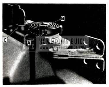
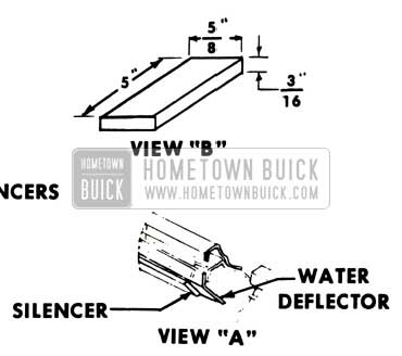
On some 1951 Series 50 and 70 cars, the door hold-open check link assemblies produce an objectionable rubbing noise when doors are operated. When customer complaints are received, this condition can be corrected by installing copper shims which act as “silencers” between the coils of the check link springs, as follows:
- Remove door inner panel hardware, trim pad and the door loading hole cover plate nearest the door check link.
- Remove the door check link by removing two screws at the door inner panel and four screws at the front body hinge pillar. Place the check link in a vise.
- Operate the check link and observe the action of the spring coils to determine where copper shims are required between the coils to prevent them from contacting each other.
NOTE: Shims can be made from copper shim stock approximately .015 thick. - If the space between coils is not sufficient to allow shim installation, the spring may be uncoiled. Using pliers grip the end of the spring, shown at “A “in Figure 72,then apply pressure against the spring and carefully lift the end over the spring stop shown at “B”.
1951 Buick Door Check Link Noise
Allow the spring to uncoil slowly until the end of the spring rests against the check link assembly at “C”.
NOTE: Extreme caution should be used in releasing or reinstalling the coil springs in Steps 4 and 6, as they are under a stress load which may cause them to “fly” and injure personnel.
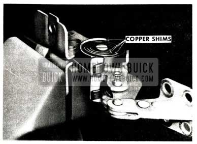
1951 Buick Door Link Copper Shims
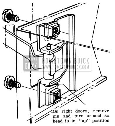
REAR DOOR CHECK LINK
The rear door check link support Group 10.608, (Part #4561013), used on 1951 four door bodies, is interchangeable for right or left sides. When the check link support is installed on left doors, the head of the pin which holds the roller is “up.” When installed on right doors, the head of the pin is “down.”
In a few cases, the pin has worked out on right doors, the ref ore, production has added a ”staking” operation on the end opposite the head.
If a replacement is made in the field on right hand doors, the service part should be checked to make sure the pin is staked as shown in Figure 74.
1951 Buick Rear Door Check Link
If the pin is not staked, it should be removed and inserted the opposite way so the head is “up.”
FRONT DOOR ARM RESTS
In the event that an owner wishes to install front seat arm rests on a 1951 Model 41, 46, 46S or 48 car, the installation can be easily made.
The necessary attaching holes and weld nuts are located in the door inner panel. Holes are also present in the door trim pads and it is merely necessary to punch the door trim fabric at these locations. The cut-outs can be located by probing the fabric with the fingers. Installation is then made with Group 14.686, Part No. 4174844, arm rest assemblies and Group 8.977, Part No. 447124, #14-10 x 2 7/16″ attaching screws (2 per arm rest).
The flat rate time allowance for this installation is .1 hr.
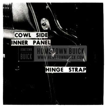
FRONT DOOR HINGE STRAP
A few cases have been reported on 1951 Series 40 jobs, in which the front door upper hinge strap contacts the cowl inner side panel when the door is being opened or closed. (See Figure 75)
1951 Buick Front Door Hinge Strap
This condition can be corrected by caulking the side panel flange inward to a point where sufficient hinge strap clearance exists.
DOOR LOCK STRIKER
A few cases have been reported on 1951 Series 40 cars, where the wrong type door lock striker plates were installed in production. Because the two types of striker plates have different serrations, wrong usage prevents the striker plate upper serrations from engaging with the adjusting plate serrations in the body pillar.
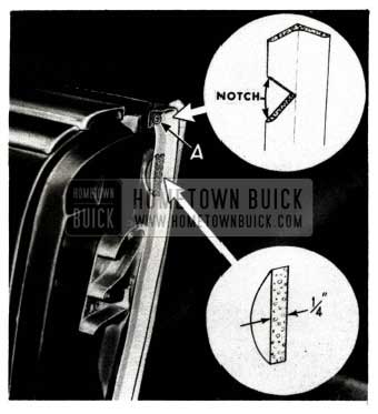
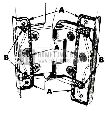
If this condition is encountered, the striker plate can be reworked as follows: (See Figure 76)
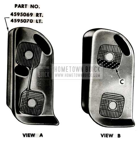
1951 Buick Door Lock Striker
- Remove the striker plate. If the serrations are like those in View “A”, reinstall striker and engage all serrations to eliminate the misaligned condition.
- If the serrations are like those in View “B”, replace the striker with the type shown in View “A”.
- If the new style striker is not immediately available, a temporary repair can be made as follows:
- File or grind the horizontal serrations from the cross-hatched area indicated at “C” in View “B”.
- Using a knife file, clean out any burrs in the remaining serrations which may have resulted from the filing or grinding operation.
- Reinstall and adjust striker plate.
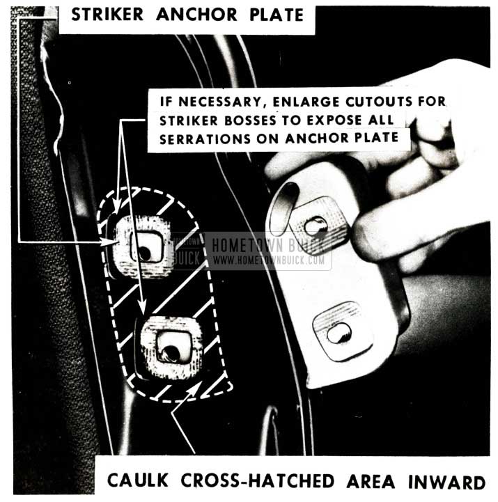
In the event the front door lock striker, on 1950 and 1951 Four Door Sedans, shifts on the center pillar due to insufficient contact between the serrations on the striker plate and anchor plates, the center pillar should be caulked inward and the cutouts for the door lock striker plate bosses enlarged if necessary.
This procedure is as follows:
- Remove the door lock striker plate.
- Check to see if the center pillar outer panel overlaps the serrations on the anchor plate. If this condition exists enlarge the cutouts in the outer panel as noted in Figure 77.
1951 Buick Door Lock Striker Anchor Plate
CAUTION: Check the amount of engagement between the door lock lift bolt and the striker plate.
72 R ROCKER MOULDING REWORK
We have received several complaints of damage to ladies stockings, caused by a poor fit at the joint made by the rocker panel moulding and rear door gravel shield extension on the 1951 Model 72R. This condition can be corrected by removing the rear and rear center rocker panel moulding retainers and reversing their installation, as shown in Figure 78,so that the longer retainer is at the rear and passes through the joint.
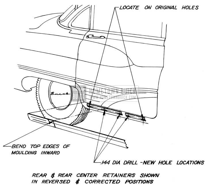
1951 Buick Model 72R Rocker Moulding Rework
It will be necessary to drill new mounting holes in the rocker panel to allow installation of the front and center screws on the long retainer and the rear screw on the short retainer. After the moulding and gravel shield extension are reinstalled, the inside top ends of the mouldings, at the joint, should be hammered slightly downward to eliminate any sharp edges.
Later production Model 72R sedans will have a single, long retainer in place of the two retainers now used. No reworking will be necessary on this later type.
FRONT WINDOW “BIND”
A few cases have been reported where front door window “bind” on 1951 Series 40 jobs is caused by faulty positioning of the molded rubber water deflectors, located on the top flange of the front door locks. This deflector is illustrated on pages 16 and 17 of Fisher Body Service News No. 6 (Buick No. 3) that was attached to BPS 2.293, dated February 15, 1951.
When this condition is encountered the deflector should be re-installed and cemented to the top flange of the lock, using 3-M Weatherstrip Adhesive.
WINDSHIELD WIPER FAILURE
1951 ALL SERIES
We have uncovered some cases of 1951 windshield wiper motor failure caused by breakage of the kicker bar. This difficulty results from incorrect installation of the snubber plate on the kicker bar and can be very easily corrected.
Due to the critical material situation all inoperative wiper motors should be checked for kicker bar breakage and, if this is the cause of failure, correction should be made as follows:
- Obtain a Trico No. 4905A Service Kit from a United Motors Service Station. This kit contains a new kicker bar and snubber plate.
- Remove the kicker, snubber plate, kicker bar and spring (see Figure 79) and discard the snubber plate and broken kicker bar.
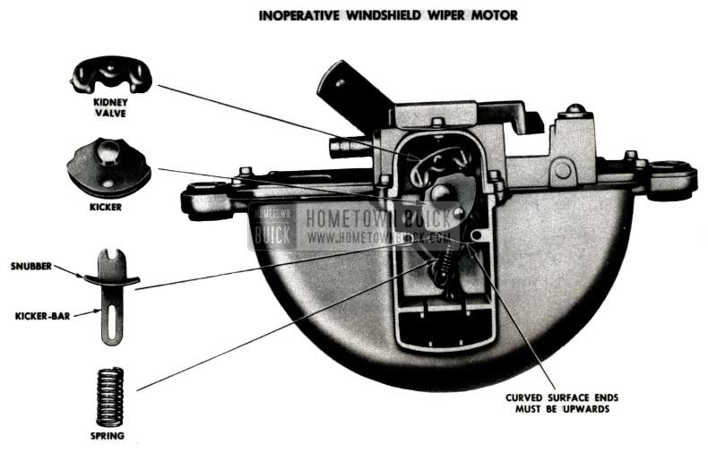
1951 Buick Windshield Wiper Assembly
REAR QUARTER WINDOW RATTLES
Rattles may occur in the rear quarter windows of 1950 and 1951 Convertibles due to lack of engagement of the quarter window guide “follower” and the flange of the guide assembly. This condition can be checked and corrected as follows:
- Lower top.
- Remove cap from rear end of quarter finish panel, and carefully remove center rear trim foundation, as shown in Figure 80.
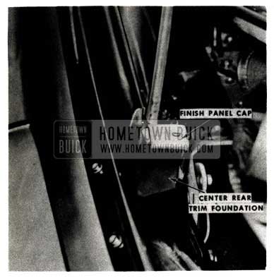
1951 Buick Remove Cap from Quarter Finish Panel
1951 Buick Folding Top Compartment Side Panel Attaching Bolts
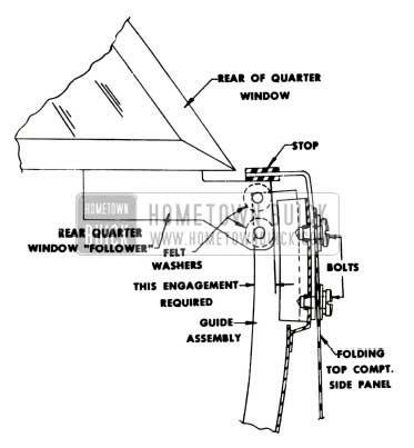
Shim the guide assembly as follows:
- Raise folding top.
- Loosen two (2) bolts attaching guide to folding top compartment side panel, shown in Figure 81.
- Lower folding top to provide working clearance at the bolt locations, shown in Figure 82.
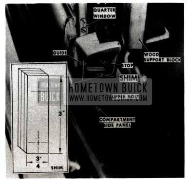
1951 Buick Lower Folding Top
Place a wood block under the side roof rails to hold top in position.
NOTE: Longer 1/4-20 bolts may have to be used. Bolts should be long enough to extend through tapped holes in guide as shown in Figure 81.
- Shut door and adjust quarter window stop for proper alignment of door glass and quarter window.
- With stop properly positioned, tighten bolts and seal bolt heads with 3-M Body Caulking Compound.
- Cement trim foundation in place with 3-M Trim Cement and install finish panel cap.
WINDOW REGULATOR RATTLES
1951 MODEL 72R
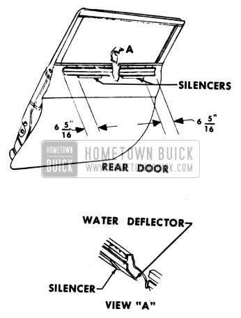
Due to occasional production variations, the front and rear door window regulator arms on 1951 Model 72R Hydro-Lectric jobs, may strike the door outer panel water deflectors and cause rattles when the windows are fully closed.
1951 Buick Front Door Window Regulator Rattles – Model 72R
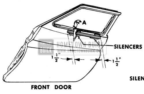
This condition can be corrected by installing longer silencers on the water deflectors as follows:
- Remove door trim pad and large loading hole cover plate.
- Lower door glass approximately 1″ from the fully closed position and remove the short silencers from the bottom of the door outer panel water deflector (Figure 84 & 85) by reaching upward through the loading hole.
- Cut new silencers from sponge rubber stock to the dimensions shown in View “B”, Figure 84.
1951 Buick Remove Short Silencers
1951 Buick Window Regulator Silencers
QUARTER WINDOW OPERATION
1951 MODEL 45R
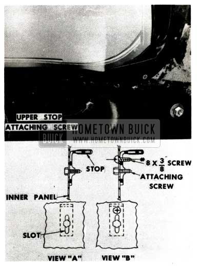
Failure of quarter windows to lower or completely raise on 1951 Model 45R Rivieras may be caused by the quarter window upper stop rotating around its attaching screw at the quarter inner panel.
When this condition is encountered, the following procedure should be used:
- Remove quarter trim.
- Loosen upper stop attaching screw, shown in Figure 86, and rotate stop to correct position (View “A”).
1951 Buick Quarter Window Attaching Screw
NOTE: If, after adjustment, stop is positioned lower than as shown, adjusting slot in inner panel may also be used for auxiliary attaching screw installation, thus eliminating the additional hole in the quarter inner panel.
- Reposition stop and install a #8 sheet metal screw, 3/8″ long, as shown in View “B”.
- Check operation of window.
- Install rear quarter trim.
SHEET METAL CORRECTION
The following sheet metal analysis and repair procedure was developed by the General Motors Institute Product Service Staff and is typical of the advanced techniques made available to Buick dealership personnel through the Buick Sheet Metal Correction Program.
STRAIGHTENING FENDER TO RESTORE PROPER HOOD ALIGNMENT
The present shortage of sheet metal parts makes it desirable to save damaged fenders whenever possible. Many fenders that are damaged in the hood ledge area are scrapped because too much difficulty in restoring alignment is anticipated. In a high percentage of cases, the fender can be straightened without unusual difficulty when the damage is properly analysed. It is necessary to recognize the pattern of metal folding and set up a procedure that will cause the metal to unfold to original shape. Whenever possible, fender removal should be avoided because the additional labor adds to the cost of repairs.
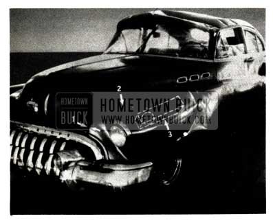
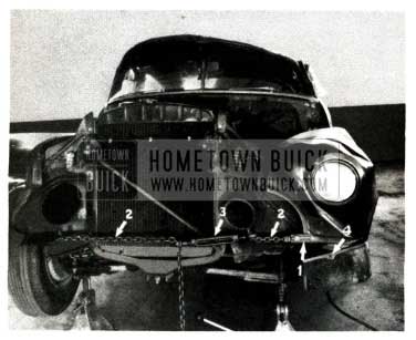
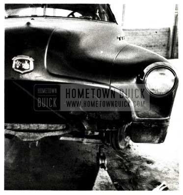
The following procedure illustrates actual repairs made to a 1950 Model 43 Buick that was “rolled”. You will note, in Figure 87, a downward blow in front as the car rolled over and a crushing effect on the rear end as ‘the car slid on its side.
1951 Buick Sheet Metal Accident Repairs
This job presents an example of particularly serious misalignment with the hood. Perfect realignment was restored in less than two hours, without removing the fender, and the remaining bumping and metal finishing was completed in a similar period of time. The discussion of the analysis and correction of this job offers suggestions that can also be applied to many similar types of damage.
- Roughing Out Front of Fender
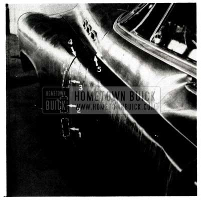
As seen in Figure 87, the impact force was downward along the top of the fender, causing an inward fold under the headlamp. The amount of misalignment is shown at (1). The fender edge (2) has been driven in so that it is overlapped by the hood. The first step in correction is to lift the upper area back into proper position.
- A wood block, 2″x4″x18″, is used under the sunken area (3) in Figure 87, to support the jack head. This provides maximum lifting effort. The lower end of the jack bears on the frame side rail as shown in Figure 88.
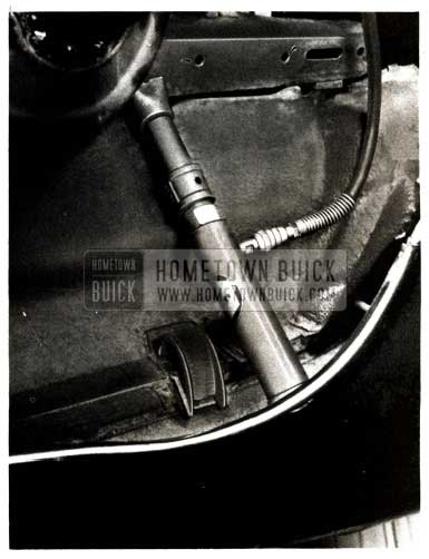
1951 Buick Front Fender Repair
1951 Buick Front End Repair
If lower section welds had not been broken, the chain could have been bolted to the cage nut (4). Note that the headlamp is left in place to avoid distortion of the opening from jack pressure.
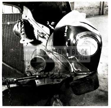
1951 Buick Headlamp Area Repair
The inward fold (1) under the headlamp has opened-up, the high ridge (2) back of headlamp has dropped proportionately and the hood ledge line (3) has started to straighten.
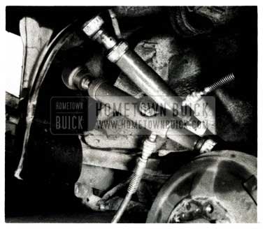
1951 Buick Rubber Bumper Control Arm
The other end of the jack is bearing against the support bracket for the rubber bumper under the upper control arm. Pressure was applied at several points along the length of the fold to avoid breaking-thru at any one point. (Prior to this picture, the area had been smoothed with a hammer and dolly block and the lower section of the fender welded into place).
1951 Buick Front Fender Alignment
The wood block under the first jack, (3) in Figure 87, can be replaced by a rubber head to finish roughing out the area back of the headlamp. A heavy hammer and smooth block of wood, 2″x4″x12″, are ideal for driving down the sharp ridges on each side of the sunken area that ran along the top of the fender (Figure 87).
- Reshaping Rear Edge of Fender and Forward Edge of Door
- The rear end of the fender inner skirt is loosened and bent forward to provide access to rear area of fender.
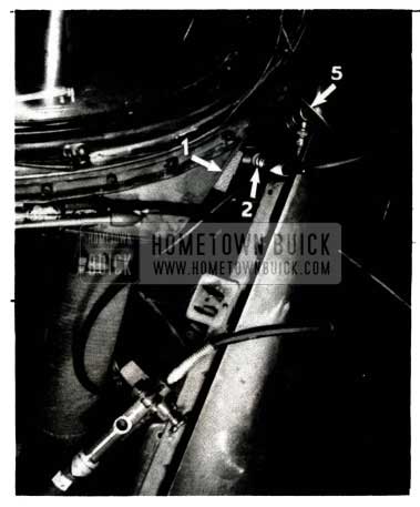
- In Figure 93 a short jack is used with a 6″ length of 1″ x 2″ board, bearing on the overlap area of the fender and door edge at (1), (2) and (3).
1951 Buick Reshaping Fender
The rear end of the jack (2) in Figure 94 is bearing on a 2″ x 4″x 16″ wood block (1) in Figure 94. A rubber head was substituted for the 6” board at (4) in Figure 93 because of the curvature at that point.
1951 Buick Fender Correction
The welds holding the edges of the door inner and outer panels were broken apart in the wreck. The procedures used in “a” and “b” have re-joined these edges in correct position.
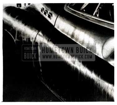
1951 Buick Roughed-Out Fender and Door
Note that alignment of the door, fender and hood is good. Minor bumping and metal finishing is all that is required to complete this phase.
DOOR WEATHERSEALING
1950-51 SERIES 50-70 RIVIERA & CONVERTIBLE
This bulletin contains a complete procedure for effective weather sealing of door openings on 1950 and 1951 Series 50 and 70 Riviera and Convertible Coupes.
Some of these procedures have been released in the same form in prior BPS bulletins, some have been revised since previous publication, and others are completely new. Particular attention should be paid to installation of the new “bulb” type side roof rail weatherstrip and the new body lock pillar weatherstrip at windhose for Riviera Coupes. The procedure for installation of the rear quarter window front lower filler strip is also new.
All parts required for the various weather sealing operations have been released for service and are available through regular channels as follows:
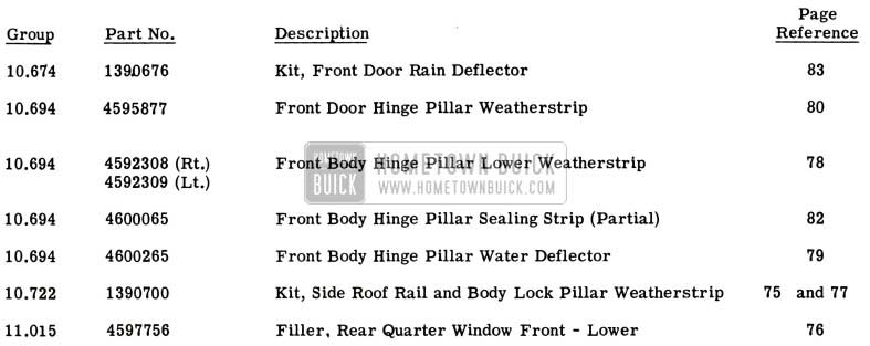
1951 Buick Door Weathersealing
The following is a list of operations that should be performed as necessary to obtain a satisfactory weather seal around the door openings on 1950 and 1951 Series 50 and 70 Riviera and Convertible Coupes. Each operation is identified in Figure 96 as follows:
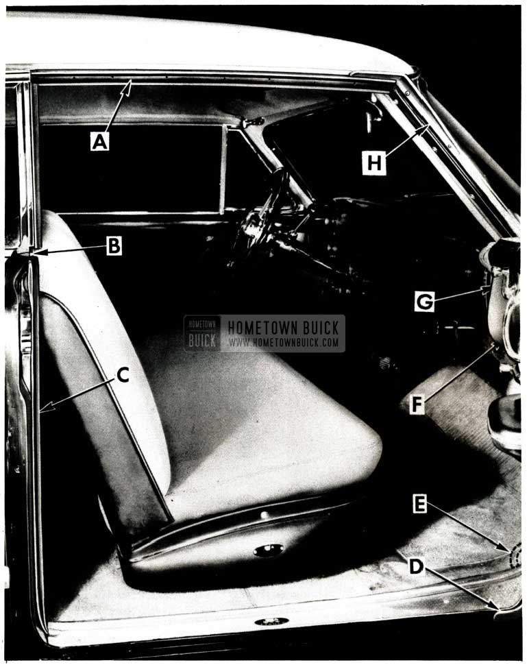
1951 Buick Door Weathersealing Operation
1951 Buick Door Weathersealing Operation Legend
It is not necessary to perform all of the individual operations listed above on every body. The entire door area should be water tested and only those operations that are required should be performed.
INSTALLATION OF “BULB” TYPE SIDE ROOF RAIL WEATHERSTRIP
(RIVIERA COUPE)
- Check alignment of door and realign with body if necessary.
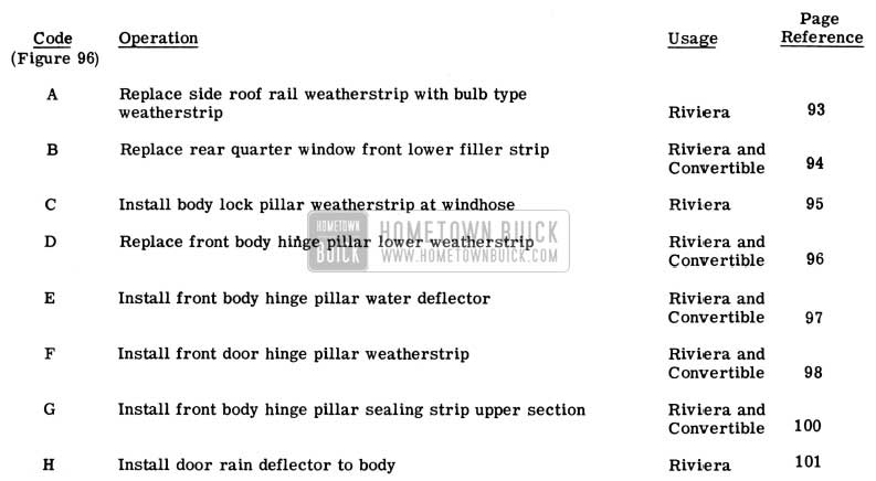
- Remove the old side roof rail weatherstrip above door. Early bodies had a continuous weatherstrip over door and rear quarter window. In these cases, the weatherstrip must be cut at the forward edge of the rear quarter sealing strip (see Figure 97).
1951 Buick Side Roof Rail Weatherstrip Installation
Some early bodies also have a continuous weatherstrip retainer over the door window and quarter window. In these cases, the retainer should also be cut to provide additional adjustments of the retainer section over the door area.
- Install the new “bulb” type weatherstrip in the retainer.
NOTE: The bulb weatherstrip has special molded ends and .should never be trimmed to shorten the length. Insert the weatherstrip into the retainer at the forward end for a distance of about 2″, then insert it at the rearward end for 2″, then start from the center and work either way.
- Check the vertical and lateral fit of the weatherstrip with the door glass as follows:
- As the door is being closed with the window in the fully raised position, the long horizontal lip of the bulb weatherstrip should clear the door window frame by approximately 1/16″ as shown in View “A’ (Figure 98).
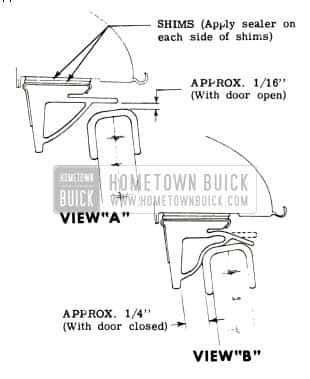
1951 Buick Side Roof Rail Weatherstrip Clearance
The weatherstrip can be lowered to obtain proper clearance by inserting waterproof cardboard shims between the weatherstrip retainer and the side roof rail. Seal both sides of each shim with a continuous bead of 3-M Autobody Sealer as shown in View “A”.
The weatherstrip retainer can be adjusted laterally to gain this clearance. In some cases, the door window may also require realignment to obtain the proper clearance.
- Cement the forward end of the bulb weatherstrip to the windshield pillar and the rearward end to the rear quarter sealing strip (see Figure 99).
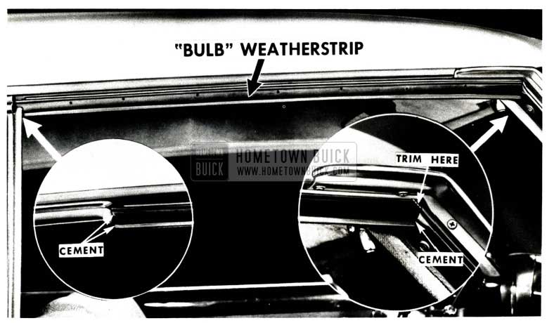
1951 Buick Side Roof Rail Bulb Weatherstrip
Use 3-M Weatherstrip Adhesive.
CAUTION: Do not cut bulb section when trimming lip.
INSTALLATIONOFNEWSTYLE REAR QUARTER WINDOW FRONT LOWER FILLER STRIP (RIVIERA COUPE AND CONVERTIBLE)
If the body lock pillar upper corner filler strip is mutilated, remove it and clean the area of old cement, then proceed as follows:
- With the rear quarter window down, drill a 1/4″ diameter hole in the center of the window opening, 1/2″ behind the edge of the door lock pillar (see Figure 100).
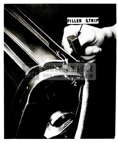
1951 Buick Rear Quarter Window Front Lower Filler Strip
NOTE: The rear quarter garnish molding can be loosened at the front to facilitate installation.
- With the quarter window up, slowly close the door and notice the fit of the filler strip to the door. A slight, brushing contact is desirable at location “Y”, ln Figure 101.
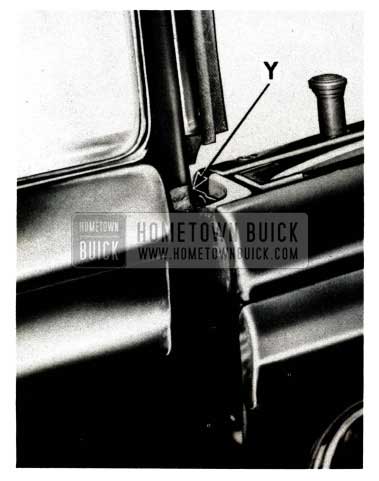
1951 Buick Rear Quarter Window Bushing Contact
The amount of contact at “Y” can be reduced by obtaining more clearance between the quarter window and the top of the body lock pillar, thus preventing the filler strip from being squeezed so far forward. This clearance is obtained by lowering the quarter window, removing the filler strip, and caulking the metal down with a hammer and caulking tool FIGURE 100 behind the hole at location “X”, in Figure 100. Do not trim the sponge rubber filler strip to obtain clearance.
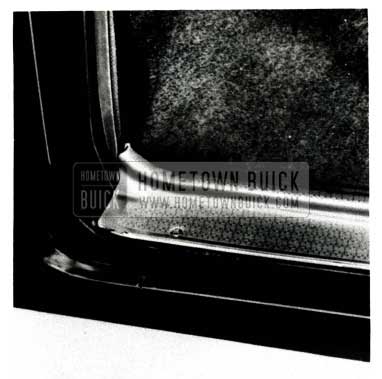
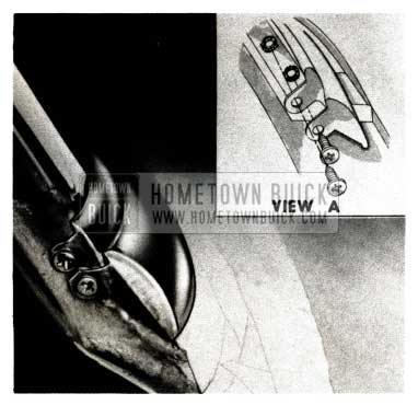
INSTALLATION OF BODY LOCK PILLAR WEATHERSTRIP AT WINDHOSE (RIVIERA COUPE)
- Loosen and remove the door sill plate.
- Cut a piece of 1/4″ thick sponge rubber filler to fit into the recess in the lock pillar as shown Figure 102.
1951 Buick Rear Quarter Window Flat Washer
Cement it in place with 3-M Weatherstrip Adhesive.
1951 Buick Door Joggle
1951 Buick Door Sill Plates
PROCEDURE FOR INSTALLATION OF FRONT BODY HINGE PILLAR LOWER WEATHERSTRIP (RIVIERA COUPE AND CONVERTIBLE)
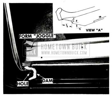
In those cases where the front body hinge pillar lower weatherstrip, indicated in Figure 105, has become torn or mutilated, the following installation procedure for the replacement of this weatherstrip should be followed:
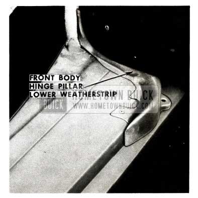
1951 Buick Front Body Hinge Pillar Lower Weatherstrip
- Remove the front door sill plate.
- Remove the damaged front body hinge pillar lower weatherstrip from the body and clean off all dried cements and sealing compounds from the rocker panel and body hinge pillar.
- Obtain a new hinge pillar lower rubber weatherstrip and temporarily install it on the rocker panel as shown in Figure 105.
- With new weatherstrip in position, carefully open and close the door and observe the amount of contact between the hinge pillar weatherstrip sealing lip and the bottom surface of the door inner panel. A brushing contact should be obtained between the door inner panel surface and the hinge pillar weatherstrip. In the event the clearance between the door inner panel and rocker panel is insufficient and would result in damage to the new weatherstrip, the following rocker panel and door bottom panel caulking operations should be performed.
- After removing the new weatherstrip from the body, carefully caulk the rocker panel down in the areas indicated by the dotted lines in Figure 106, to obtain the necessary clearance for the hinge pillar weatherstrip.
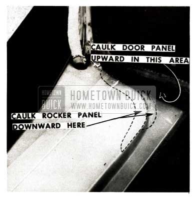
1951 Buick Caulk Rocker Panel
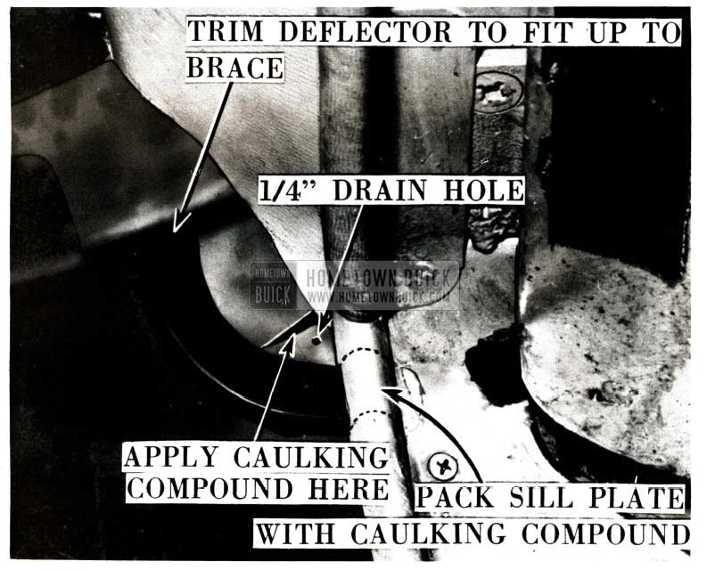
FRONT BODY HINGE PILLAR WATER DEFLECTOR INSTALLATION
(RIVIERA COUPE AND CONVERTIBLE)
- Remove the door sill plate assembly and pack the front portion of the sill plate with 3-MCaulking Compound as shown in Figure 107.
1951 Buick Front Body Hinge Pillar Water Deflector
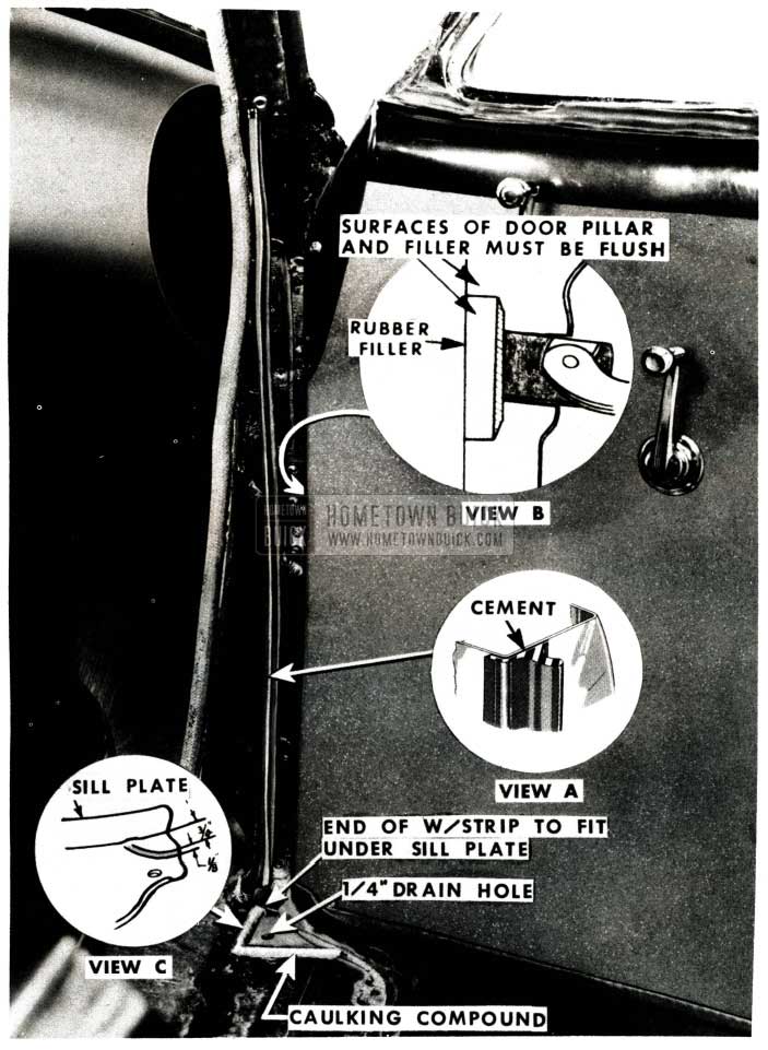
PROCEDURE FOR INSTALLING FRONT DOOR HINGE PILLAR WEATHERSTRIP
(RIVIERA COUPE AND CONVERTIBLE)
- Apply masking tape along the front edge of the door trim pad to protect the door trim from being soiled during the following operations.
- Remove the screw and clip or washer at the lower front corner which holds the end of the door bottom weatherstrip to the door hinge pillar as shown in View “C” in Figure 110.
1951 Buick Front Body Hinge Pillar
1951 Buick Front Body Hinge Pillar Sealer
1951 Buick Front Body Hinge Pillar Plates Autobody Sealer
NOTE: The door in Figure 110 has been removed for illustration purposes only. It does not have to be removed from the body to make the repair outlined on this page.
- Cement the rubber filler to the door hinge pillar at the check link cut-out as shown in Figure 110. Use 3-M Weatherstrip Adhesive.
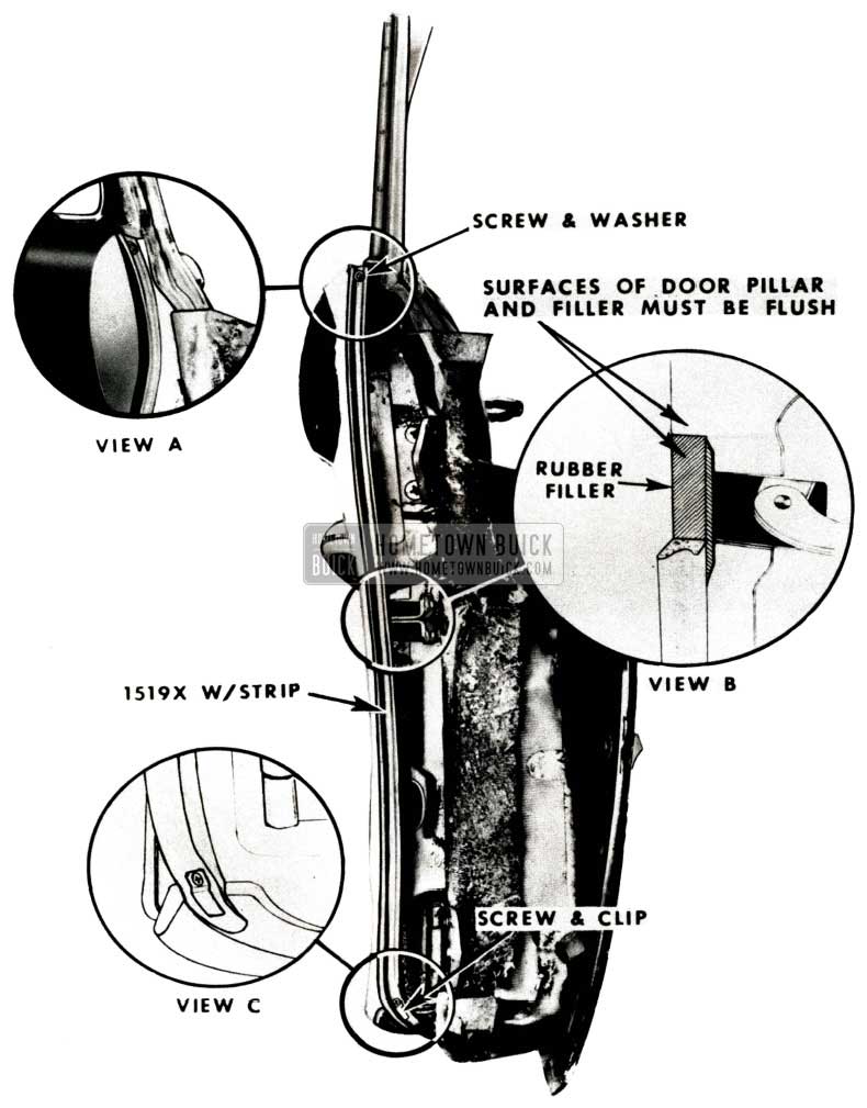
- Install the weatherstrip to reach from a point approximately 1″ above the top of the door finishing panel, down along the inner corner of the door hinge pillar, and overlap the door bottom weatherstrip at the lower corner (See Figure 110). Taper both ends for a length of about 2″ as shown in Views “A” and “C”.
- NOTE: During 1950, a front body hinge pillar lower weatherstrip (shown on page 96) was incorporated in production. This weatherstrip, which was installed at the bottom of the body hinge pillar on the rocker panel, cancelled the front corner section of the door bottom weatherstrip. U this type of installation is encountered, the bottom end of the hinge pillar weatherstrip is fastened with a screw and washer to the door hinge pillar without the overlap shown in View “C”.
- Apply 3-M Weatherstrip Adhesive to the door hinge pillar {where the weatherstrip is to be cemented) and to the weatherstrip. Install the weatherstrip as follows:
- Remove the screws at the front of the door finishing panel.
- Place the weatherstrip along the inner edge of the door hinge pillar with the top end of the weatherstrip inserted under the upper flange of the door finishing panel as shown in View “A” of Figure 110.
1951 Buick Front Body Hinge Pillar Sealing Strip
The lower end of the weatherstrip must overlap the door bottom weatherstrip on the outside of the inner lip to direct any water outward, on those bodies which incorporate a door bottom front corner weatherstrip, as shown in View “C”.
FRONT BODY IDNGE PILLAR SEALING STRIP UPPER SECTION REPAIR
(RIVIERA COUPE AND CONVERTIBLE)
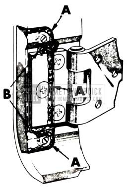
If waterleaks are encountered, due to the top of the front body hinge pillar sealing strip being ripped or torn above the upper hinge, a partial “front body hinge pillar sealing strip” (see Figure 111) may be installed according to the following procedure:
NOTE: If the rip extends below the upper hinge, an entire new sealing strip should be installed.
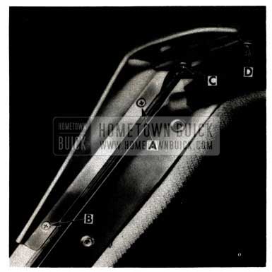
- Raise the hood.
- Loosen the portion of the door upper weatherstrip that is cemented over the top of the sealing strip (See Figure 112).
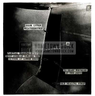
1951 Buick Front Body Hinge Pillar Sealing Strip Removal
1951 Buick Front Body Hinge Pillar Sealing Strip Installation
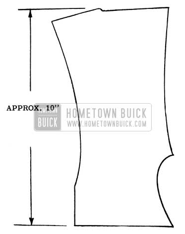
The bottom of the partial sealing strip should be allowed enough fullness when the door is closed to prevent any strain at that point. When the correct position is established, mark the location of the partial sealing strip on the body hinge pillar with a piece of chalk.
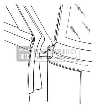
NOTE: The curved end of retainer MUST be tight against front body pillar as shown in Figure 114.
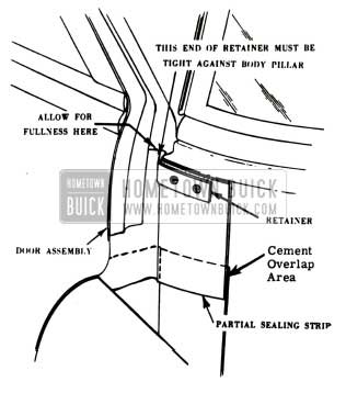
1951 Buick Front Body Hinge Pillar Partial Sealing Strip
- Clean any excess cement from the repair area and install the hood bumper and the fender attaching bracket.
INSTALLATION OF DOOR RAIN DEFLECTOR TO BODY (RIVIERA COUPE)
- Remove and discard the door rain deflector that is attached to the ventuator frame. Reinstall the three attaching screws to the ventilator frame for appearance.
- Hold the new rain deflector in position on the body and mark the location for screws “A” and “B”. (See Figure 115).
1951 Buick Door Rain Deflector Installation
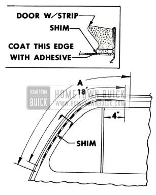
FRONT DOOR WEATHERSTRIP
On some 1951 Series 40 jobs, the spacing ov.er the front door ventilator area between the side roof rail and the door assembly is excessive. This prevents the door weatherstrip from providing a good sealing contact and it is necessary to correct the condition as follows:
- Check the alignment of the door in the body opening. If the door should be moved up and/ or forward, make these adjustments. (Refer to Fisher Service News, Buick No. 3, that was attached to BPS 2.293, Feb. 15, 1951.)
- After the door has been adjusted, check the seal of the weatherstrip along the door header.
- If the seal is still not satisfactory, the weatherstrip may be shimmed as shown in the illustrations.
- Loosen the door weatherstrip along the length indicated by “A” in Figure 115 and remove all dried cement from door.
1951 Buick Front Door Weatherstrip
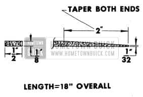
1951 Buick Weatherstrip Shim
FRONT DOOR WEATHERSTRIP
Some cases have been encountered where the lip of the front door bottom weatherstrip, on 1951
Series 40 jobs, closes over the door drain holes when the door is closed. If this condition exits water may become trapped between the door inner and outer panels and eventually cause leakage at the lower hinge recesses.
When this condition is found, the weatherstrip should be reworked at the locations indicated 1n Figure 117, as follows:
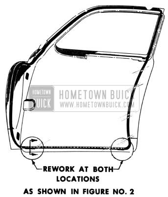
1951 Buick Front Door Weatherstrip Illustration
- Cut “V” notches in the “valve” sections of the weatherstrip as shown in Fig. 118.
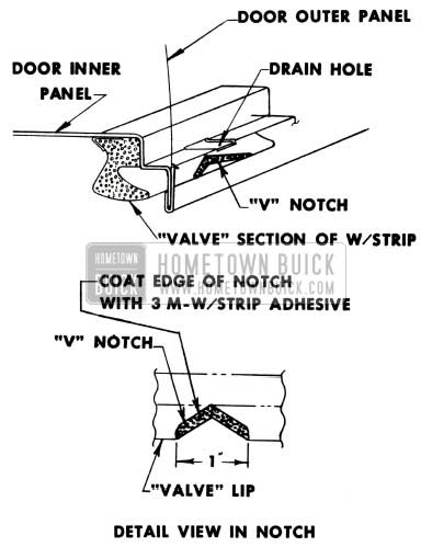
1951 Buick Front Door Weatherstrip Rework
Notches should be deep enough to permit adequate drainage through the door drain holes.
LOCK PILLAR WEATHERSTRIP
1951 CONVERTIBLE AND IDVIERA COUPES
Some trouble has been encountered with unsatisfactory adhesion of the Body Lock Pillar Auxiliary Weatherstrip (at windhose) now being used on all 1951 Convertible and Riviera Coupe models. This condition is caused by a film of glycerine on the cementing surface of weatherstrips used during the first few days production and has now been corrected at the source.
When this trouble is experienced, the weatherstrip should be removed, cleaned and reinstalled as follows:
- Remove the weatherstrip from the body lock pillar.
- Clean the cementing surface of the weatherstrip with gasoline. Use gasoline sparingly.
- Clean all old weatherstrip cement from the body lock pillar.
- Re-cement the weatherstrip to the body pillar adjacent to the windhose (Figure 119) with 3-M Weatherstrip Adhesive.
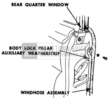
1951 Buick Door Lock Pillar Weatherstrip
FRONT DOOR WEATHERSEALING
1950-51 SERIES 50-70 CONVERTIBLE AND RIVIERA
A new front door inner panel weather sealing operation has been incorporated in production on 1951 Series 50 and 70 Convertible and Riviera Coupes. This operation will divert any water that may enter the body at the ventilator pivot, between the door panels for drainage, and prevent water stains on door trim pads.
When weather sealing 1950 and 1951 jobs that do not have this added operation, the following procedure should be used:
- Brush 3-M Weatherstrip Adhesive on the front door inner panel in the area designated by cross-hatched lines in Figure 120.
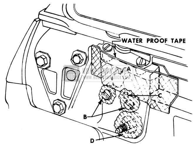
1951 Buick Door Lock Pillar Waterproof Tape
WINDSHIELD MOULDING WATERLEAKS
1950-51 SERIES 50-70
We have received a few reports of a waterleak condition at the windshield reveal and belt moulding screws, located on the front body hinge pillar on 1950 and 1951 Series 50 and 70 cars. Water entering the body at this location may collect along the bottom flange of the instrument panel and spill over when the car makes a turn.
If this condition is encountered, the screw holes should be sealed with 3-M Autobody Sealer as shown in Figure 121.
1951 Buick Windshield Moulding Waterleak Repair
HINGE PILLAR WEATHERSTRIP
1950-51 SERIES 50-70
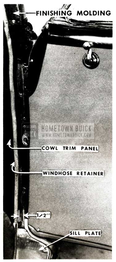
A new front body hinge pillar weatherstrip has recently been incorporated in Series 50 and 70 production and is available for service on 1950 and 1951 Series 50-70 jobs that are not equipped with an original door hinge pillar auxiliary weatherstrip. The new weatherstrip, Group 10.694, Part No. 4603809, provides an improved seal in the hinge pillar area and reduces door closing effort present with the former strip.
Installation should be made as follows:
- Remove the cowl trim pad, windhose retainer attaching screws, and door sill plate, shown in Fig. 122.
1951 Buick Front Body Hinge Pillar Weatherstrip
On Convertible and Riviera coupes, loosen the front body hinge pillar finishing molding also shown in Figure 122.
NOTE: If a front body hinge pillar lower weatherstrip (gooseneck) is installed on the floor pan, this weatherstrip should be trimmed off as shown in Fig. 122 to provide 1/2″ clearance between the windhose and weatherstrip.
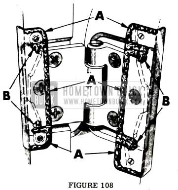
- Remove the three (3) hinge cover plates from the front door and front body hinge pillar.
- Apply 3-M Autobody Sealer in a full and continuous ribbon to the hinge cover plates across the top and bottom and along the edge as indicated at “A” in Figures 123 and 124.
1951 Buick Front Body Hinge Pillar Plates Sealer
1951 Buick Front Body Hinge Pillar Plates Autobody Sealer
1951 Buick Front Body Hinge Pillar Weatherstrip Position
On Convertible and Riviera coupes the upper end of weatherstrip is inserted under end of pillar finishing molding.
ROOF RAIL WATERLEAKS
1951 MODELS 56C – 76C
We have received a few complaints of waterleaks at the junction of the front and side roof rails and door ventilators on 1951 Series 50 and 70 Convertibles that are equipped with the new type front roof rail weatherstrip. (This weatherstrip has been used in production since approximately June 15, 1951.)
When this leaking condition is encountered, the weatherstrip installation should be reworked as follows:
- Remove screws “A” and “B” shown in Figure 127.
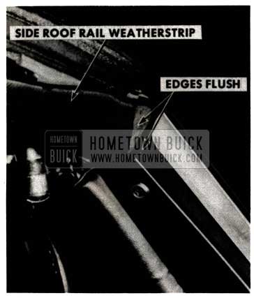
- Loosen molded end of weatherstrip from front roof rail and stretch weatherstrip outward to align edge flush with rabbet as shown in Figure 126.
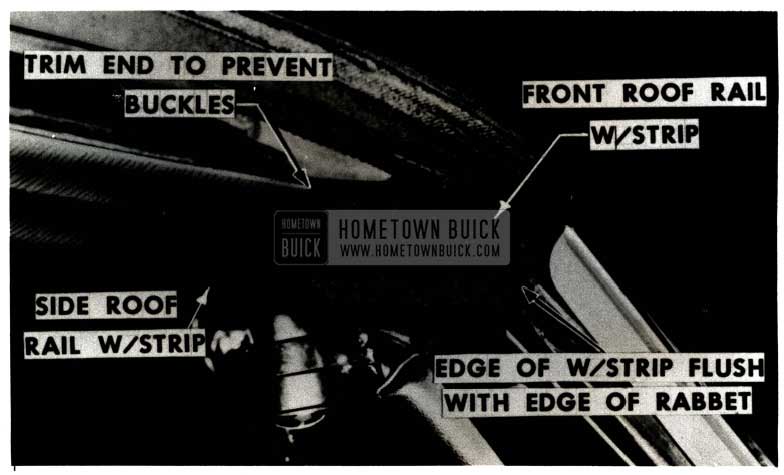
1951 Buick Roof Rail Waterleak Repair
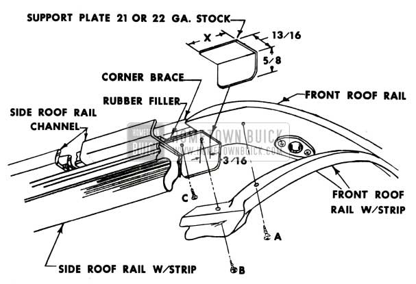
1951 Buick Roof Rail Assembly
- Length “X” should be sufficient to extend 3/16″ forward of screw location “B” with the rear edge butting against the front end of the side roof rail channel.
- After fitting, plates should be filed free of burrs and sharp corners, primed and painted black.
NOTE: This is a door hinge cover plate screw.
- Apply 3-M Weatherstrip Adhesive to the following surfaces:
- Top cementing surfaces of front roof rail weatherstrip and corresponding surfaces of front roof rail and support plate.
- Rear end of front roof rail weatherstrip and front end of side roof rail weatherstrip.
- Position front roof rail weatherstrip and install screws “A” and “B”.
- Allow cement to dry thoroughly before locking folding top.
SIDE ROOF RAIL WEATHERSTRIPS
1951 SERIES 40-50-70 CONVERTIBLES
New type side roof rail weatherstrips and retainers are now being used on all Series convertibles. The molded outer corners, formerly a part of the front roof rail strip, have been made an integral part of the new side rail weatherstrips (Fig. 128) and a cored hole has been incorporated in the front section to improve locking action of the top.
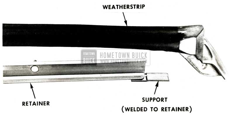
1951 Buick Roof Rail Weatherstrip
The new retainers have a welded support at the front end (Fig. 128) which provides addition support for the molded front corners of the weatherstrips.
When waterleaks are encountered at the front corners of the side roof rail, on bodies built after elimination of the windshield header weatherstrip (approximately June 15 on Series 50-70 and entire model year on Series 40), we recommend installation of the new weatherstrips and retainers. Parts information is as follows:
WEATHERSTIDP, FOLDING TOP SIDE ROOF RAIL (FRONT) GROUP 14.120
Part No. – Series
4606850 – 40 (Right)
4606851 – 40 (Left)
4607723 – 50-70 (Right)
4607724 – 50-70 (Left)
RETAINER, FOLDINGTOP SIDE ROOF RAIL WEATHERSTRIP (FRONT) GROUP 14.120
Part No. – Series
4592408 – 40 (Right)
4592409 – 40 (Left)
*4601010 – 50-70 (Right)
*4601011 – 50-70 (Left)
*Part numbers did not change. New retainers must be identified by welded support (Figure 128).
The installation procedure is as follows:
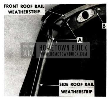
- Remove old side roof rail front weatherstrips and their retainers.
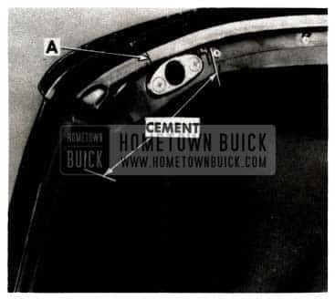
- Detach molded ends of front roof rail weatherstrip from rail by removing screws at “A” in Fig. 129 and loosening weatherstrip approximately to end of retainer at “B”.
1951 Buick Front and Side Roof Rail Weatherstrip
1951 Buick Side Roof Rail Weatherstrip
- With top locked, front surface of weatherstrip should seal against angular surface of windshield pillar.
- Front outer edge of weatherstrip should be flush with edge of pillar rabbet, as indicated.
- Scribe location of weatherstrip on front roof rail and corner braces for cementing operation which follows:
1951 Buick Cement Front Roof Rail Weatherstrip
LIFT GATE WATERLEAKS
1951 MODELS 59-79
Waterleaks at the rear body header on 1951 Estate Wagons may be caused by interference between the header weatherstrip and lift gate top rail. When this condition occurs, the inside corner of lift gate tends to snag the weatherstrip, while being raised, and roll it away from the body. A suggested method of providing adequate clearance at this point is shown in Fig. 132.
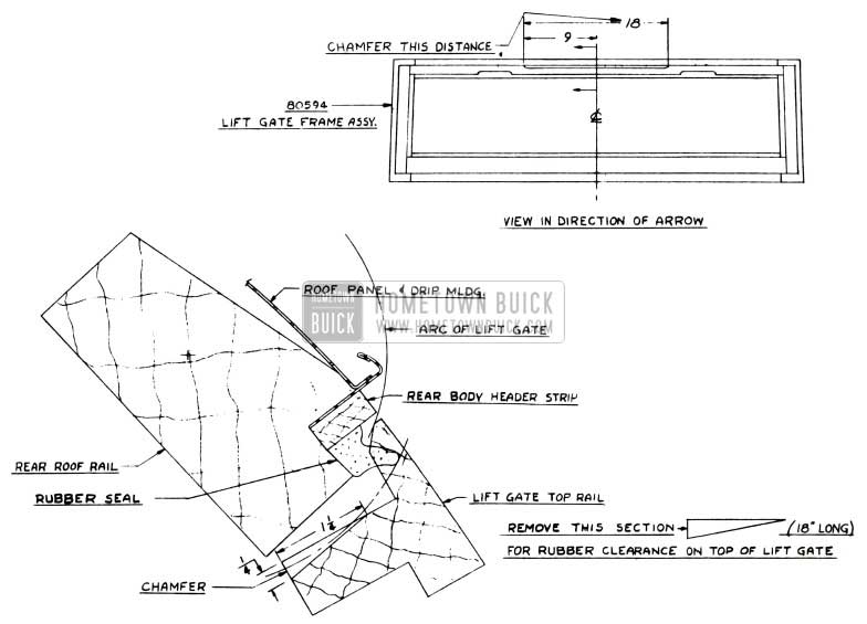
1951 Buick Estate Wagon Lift Gate Waterleak Repair
After the lift gate rail has been chamfered, the weatherstrip should be checked and recemented if necessary.
Leave A Comment
You must be logged in to post a comment.