DYNAFLOW OIL CHANGE
1948 THRU 1951 DYNAFLOW
Supplements Sec. 1-A, Par. 1-4, 1951 SM and Sec. 5, Par. 20{b), 1948-49-50 Dynaflow SM.
At the 25,000 mile Dynaflow oil change, the oil pan and screen should be removed from the transmission and thoroughly cleaned before the transmission is refilled with new oil.
DYNAFLOW PUMP COVER NUTS
1951 SERIES 40-50-70 DYNAFLOW
We have completed a one week trial run using a modified Dynaflow Primary Pump Cover Nut. The transmissions subject to this deviation may be identified by numbers F-261 through 265 and G-261 through 265.
The nut may be easily distinguished from the production nut in that the slotted portion is turned down leaving the hexagon below the slots.
In the event any of these require replacement in service, it is requested that for every nut replaced by a production type nut, the one diametrically opposite should also be replaced in order to insure proper balance.
DYNAFLOW CONVERTER ASSEMBLY
1948 THRU 1951 DYNAFLOW Supplements Sec. 4-E, Par. 4-38(i), 1951 SM and Sec. 7, Par. 40(k), 1948-49-50 Dynaflow SM.
The following procedure should be followed after a Dynaflow Converter, equipped with the old type cover and flat gasket, has been disassembled:
- A new flat converter cover gasket should be installed.
- The primary pump cover bolts should be tightened to 30-35# ft. torque at build up.
- The transmission should be operated sufficiently to heat the Dynaflow oil, allowed to cool, and the primary pump cover bolts retorqued to 27-32# ft.
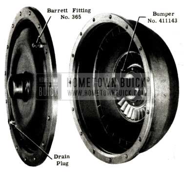
CONVERTER DRAIN PLUGS
1951 DYNAFLOW
The recessed hex. head converter drain plugs, now used on Dynaflow transmissions with the “O” ring type pump cover seal, will be replaced in production by a longer plug with external hex. head (Part No. 1345487).
Whenever a new type plug is used to replace the recessed head type, both plugs must be changed. This is necessary to maintain correct converter balance.
CONVERTER LEAKAGE TEST Supplements: Sec. 7, Par. 32 {d) and Figs. 55 and 108, 1948-49-50 Dyn. SM; Sec.4-E, Par. 4-30 {d) and Fig. 4-95, 1951 SM.
We have received a report stating that a rubber tank ball, being used to test a converter primary pump for leakage, was blown through the pump hub. Due to the possibility of injury to personnel, we recommend that this method of testing be discontinued. In the future, a lower control arm rubber bumper, Group 7.422, Part No. 411143 should be used in place of the tank ball as shown in Figure 14.
1951 Buick Dynaflow Converter Leakage Test
PRESSURE REGULATOR VALVE
In BPS 2.273, April 17, 1950, we informed you that the converter pressure regulator valve and spring should be removed and discarded when a Dynaflow transmission is removed for service. We have recently uncovered cases where front pump seal leakage can be attributed to excessive pressure in the converter. For this reason, removal of the valve and spring will very likely prevent future trouble and owner expense.
Engineering tests have shown that the pressure resulting from the lube pressure regulator valve, plus the back pressure from the cooler, provides ample pressure in the converter for satisfactory operation.
DYNAFLOW CONVERTER CLEARANCE
Supplements: BPS 2.307, Page 119; Sec. 4-C, Par. 4-16 and Sec. 4-E, Par. 4-38 (i) and Fig. 4-151, 1951 SM; Page 99 (chart) 1948-49-50 Dyn. SM.
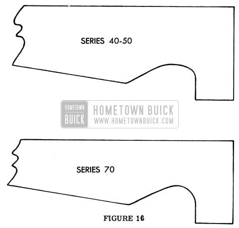
Recent changes in the Dynaflow primary pump and cover assemblies (BPS 2.307, page 119) have necessitated a change in the design of converter clearance gauges 1 3045 and 1 2596. Gauges now in the field can be reworked to conform with the templates shown in Figure 15, which are actual size.
1951 Buick Dynaflow Converter Clearance Chart
Both ends of the gauge must be reworked, using a round file in the curved areas and a flat file for straight edges. Care must be taken when clamping the gauge in a vise so that it is not bent, or nicked on the ground edges. In addition, metal should be removed in a manner that will not generate enough heat to cause warpage.
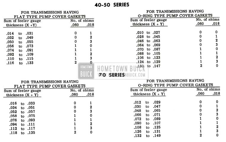
After the gauges are reworked, they can be used with either type primary pump and cover, but the new converter shimming chart shown in Figure 16 must be used.
1951 Buick Dynaflow Converter Shipping Chart
SHIMMING CHART FOR CONVERTER CLEARANCE
DYNAFLOW CLUTCH PLATES
1951 SERIES 70
Supplements Sec. 4-E, Para. 4-34, 1951 Shop Manual.
Starting with Series 70 Dynaflow transmission No. G-310, a new internally splined clutch plate was put into production. The new plate can be easily identified by the facing material. On one side of the plate, the outer diameter is faced with cork and the inner diameter is faced with a composition material known as “Krafelt”. On the reverse side of the plate, “Krafelt” is used on the outer diameter and cork on the inner.
At the present time the new type plate will not be supplied for service. If it becomes necessary to make a replacement, the entire pack of internally and externally splined plates should be replaced with the regular service plates.
DYNAFLOW CLUTCH PLATES
1951 SERIES 70 DYNAFLOW
The internally splined Cork-Krafelt clutch plates, used in Series 70 Dynaflow transmissions since code No. G-310, have been discontinued effective with transmission No. G-375. The semi-metallic plates with spiral grooves, as used in Series 40-50 transmissions, have been reinstated.
In the event that a Cork-Krafelt plate requires replacement, all five plates must be replaced, using the Group 4.163, Part No. 1-393673 Internal Splined Clutch Plate Kit. This is necessary to insure satisfactory clutch operation.
We wish to emphasize that different type clutch plates must never be intermixed in the same transmission.
DYNAFLOW REACTION SHAFT & RETAINING RING
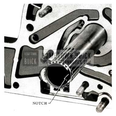
Effective with Dynaflow Transmissions F-89 (40-50) and G-89 (70) the notch in the front side of the reaction shaft was eliminated to facilitate manufacturing, (see Figure 17).
1951 Buick Dynaflow Reaction Shaft
A tang has been added to the retaining ring at the gap to simplify assembly and disassembly of the ring from the new type shaft, (Figure 18).
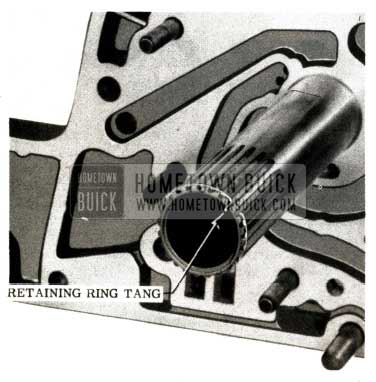
1951 Buick Dynaflow Retaining Ring
Always make sure the tang lies between the splines on the reaction shaft when the ring is firmly seated in the groove on the shaft.
The new retaining ring can be used on all previous reaction shafts and will be carried for all service replacements.
This modification does not affect interchangeability and the flange and ring part numbers were not changed.
DYNAFLOW REVERSE SERVO PISTON
Effective with Dynaflow transmissions F-127 (40-50) and G-127, (70) the size of the oil metering hole to the reverse servo piston has been increased from .070″ to .082″. (See Figure 19)
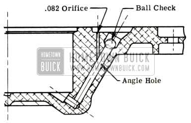
1951 Buick Dynaflow Reverse Servo Piston
This change will result in a faster application of the reverse band and improve the “rocking” ability of the car.
This change can be made in the field on transmissions with the two stage reverse servo piston if required. The oil pan, valve body, and servo body should be removed and the metering hole enlarged to .082″ (#45 Drill). Special care must be exercised to run the drill point to the centerline of the angle hole. Blow out the metering hole, angle hole, and servo well to remove all chips.
Current part numbers are not affected by this modification.
DYNAFLOW CLUTCH PISTON
Effective with Dynaflow transmissions F-164 (40-SO) and G-164 (70) the high clutch piston and ball check valve were redesigned to provide a more positive and rapid exit of the oil from the apply side of the piston. The new piston is lighter and the ball check valve is installed on the apply side of the piston. The piston bleed hole, which has been increased in size, discharges into a relief on the rear side of the piston. A comparison of operating features of the former and new type piston assemblies is shown in Figure 20.
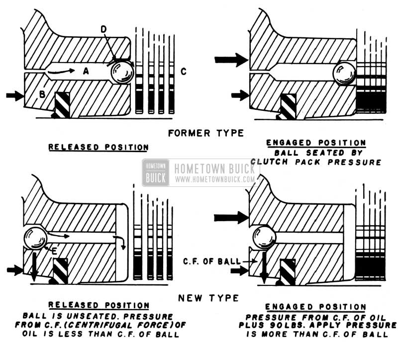
1951 Buick Dynaflow Clutch Piston
With the former piston, the bleed-off passage (A) remained open until ninety pounds of oil pressure was introduced behind the piston (B), by shifting into “drive” position. This caused the piston to move toward the pack of high clutch plates (C), engaging the clutch and forcing the ball check valve (D) to seat and close the passage. When the pressure of ninety pounds was released, the high clutch piston return spring forced the piston back, and as it moved away from the clutch plates, the remaining pressure forced the ball to unseat.
In the new high clutch piston valve design the ball check valve has been moved to the other end of the oil passage and must move up a ramp (E) before it can seal off the passage. Rotation of the piston prevents the ball from moving up the ramp until the pressure of ninety pounds is applied behind the piston which seats the ball and moves the piston toward the clutch plates. Thus, with this new design, seating of the ball check valve is accomplished by the applied oil pressure proceeding any movement of the clutch piston.
The new high clutch piston Group 4.166, Part No. 1343578 is interchangeable with the old design and will be carried for all service replacements when stocks of the old type are exhausted.
DYNAFLOW PRIMARY PUMP
1951 ALL SERIES
Supplements Sec. 4-C, Para. 4-16 and Sec. 4-E, Para. 4-38 (i) and Fig. 4-151, 1951 Shop Manual.
Effective with Dynaflow transmissions F-338 (Series 40-50) and G-338 (Series 70) a change has been made in the converter primary pump and cover assemblies to provide a more positive seal against oil leakage. The new cover requires only 15 assembly bolts (12 for cover to pump and three for flywheel to pump) and utilizes an “O” type sealing ring in place of the former flat gasket. The pump assembly change involves a chamfer on the inside corner of the cover mounting flange to accommodate the “O” sealing ring.
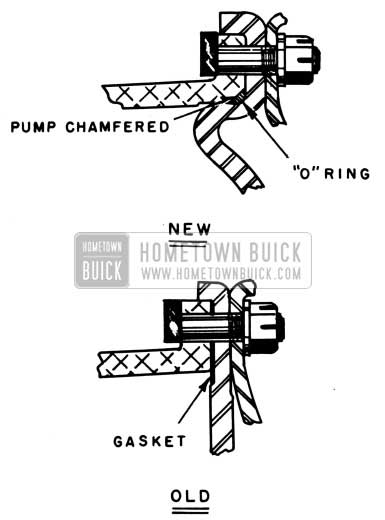
1951 Buick Dynaflow Primary Pump
From Figure 21 it can be readily seen that the new and old type pump covers are not interchangeable. The redesigned pump will be the only one supplied for service after present stocks are exhausted, thus any jobs requiring a new pump will also require a new type cover, seal and related items. The old type cover will still be supplied for service replacement on jobs having the old type primary pump. All parts affected by this change (pump, pump cover, cover seal, balance weights, plugs, bolts, nuts and washers) are listed in Supplement No. 6 to the 1951 Chassis and Body Parts List, dated September 1, 1951.
When ordering Group 4.005, Part Nos. 1390564 and 1390565, Transmission Gasket Kits for service on transmissions having the new primary pump and cover, it will also be necessary to order the “0” type sealing ring and discard the pump cover gasket that is included in the kit.
The service procedure for ”Installation of Bell Housing and Torque Converter”, Section 4-E, Paragraph 4-38 (i), 1951Buick Shop Manual should be revised for use with4he new primary pump and cover as follows:
Step 3 – Converter Clearance Gauges No. J 3045 and 1 2596 must be reworked for use with new type pump cover. Instructions will be issued in the near future
Step 9 – The converter clearance shimming chart shown cannot be used with the new pump and cover. A revised chart will be issued in the near future.
Step 10 -Install the primary pump cover with a new “0” sealing ring. Make sure the ring is not twisted and then install bolts with plain washers and safety nuts against the cover – do not tighten bolts. Position converter so that drain plug between the two bolt holes is on top (Figure 22) and install first bolt to the right of the drain plug.
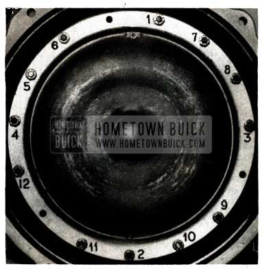
1951 Buick Install Dynaflow Primary Pump Cover
Going clockwise, omit a bolt every fifth hole to provide for the flywheel to pump driving bolts. Note: Be sure that bolts and bolt heads are all the same length.
Step 11 – Figure 4-151 is not applicable to the new pump cover. Use tightening sequence shown in Figure 22 of this bulletin and tighten all bolts to 25-30 ft. lbs.
Caution: Until instructions for reworking the converter clearance gauges and ‘a new shimming chart are released, it is important to note the number of shims installed in production and to use the same shimming combination when the converter is reinstalled. Although this procedure may not prove entirely accurate, it is the best that can be done under the circumstances.
DYNAFLOW SECONDARY PUMP
Effective with Dynaflow transmissions F-168 (40-50) and G-176 (70) the secondary pump thrust washer was eliminated from the converter assembly in connection with use of a redesigned secondary pump assembly. The new pump has a cast boss which bears directly on the primary pump hub (See Figure 23); can be used on all past series Dynaflow transmissions; and will be carried for all service replacements.
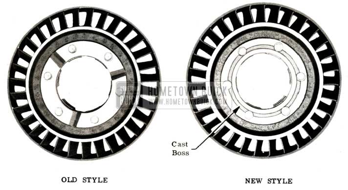
1951 Buick Dynaflow Primary Pump Hub
Whenever a new style secondary pump is installed, the thrust washer should be removed and discarded.
Parts information is as follows:
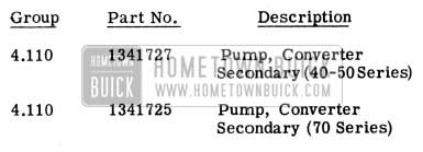
1951 Buick Dynaflow Secondary Pump Parts
TORQUE BALL RETAINERS
1951 ALL SERIES
Early in July, 1951, production cars will be equipped with new torque ball inner and outer retainers made of thinner stock. These provide an advantage over present heavy retainers in that they are easier to shim for proper fit, more uniform in load when adjusted as specified, and they will hold their adjustment for a longer period of time.
At the same time, we are revising the torque ball adjusting procedure given in Section 4-B, paragraph 4-12 of the 1951 Shop Manual, to provide a more convenient and positive method of fitting and “feel”. The revised procedure is also applicable to the heavy retainers formerly used, and affects Steps #11 through 15 and Figures 4-23 and 4-24 of paragraph 4-12, as follows:
- Prepare a hardwood club for adjusting torque ball as shown in Figure 4-23. (Note: The dimensions given in Figure 4-23 should be revised to agree with the club as shown in Figure 24 of this bulletin.
- Insert the hardwood club in universal joint and while moving torque ball up, down, and sideways tighten retainer bolts evenly. CAUTION: It is necessary to frequently move torque ball while tightening bolts in order to properly center the ball and retainers. If torque ball binds as bolts are tightened, tap outer retainer lightly at several points, using rawhide or other soft mallet. This will usually relieve the binding condition.
- Attach spring scale to club at groove located 14 3/8″ from end of universal joint and test pull required to move torque ball when all bolts are tight. See figure 4-24. (Note: Figure 4-24 should be revised so that the dimension from the end of the universal joint to the groove in club reads 14 3/8″ and the lbs. pull indicated by the scale is 15-25 lbs.) A drag of 15 to 25 pounds should be obtained. If torque ball is too tight or too loose, loosen bolts and repeat the centering and tightening operation, then recheck drag with club and spring scale.
- If torque ball is too tight after repeating the centering and tightening operation remove outer retainer and increase total thickness of shims; if ball is too loose, decrease total thickness of shims. Shims are furnished under Group 5.560 in five thicknesses, and are notched on outer edge for identification as follows:
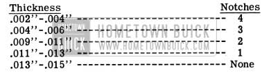
1951 Buick Torque Ball Shim Thicknesses
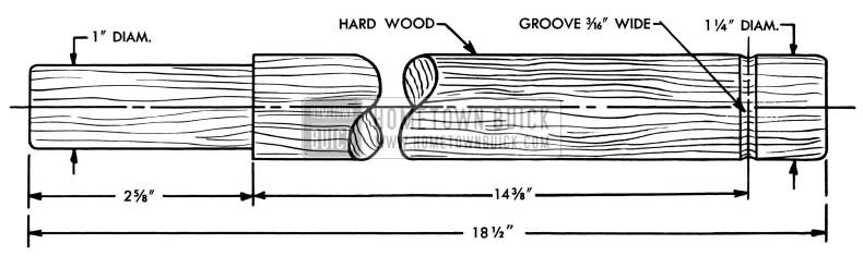
1951 Buick Hardwood Torque Ball Club
After changing shims always install ball and retainer with top sides up and use the tentering, tightening, and checking procedures specified in steps 12 and 13 above.
Final adjustment must provide a uniform drag of 15 to 25 pounds with scale applied at groove in club. See figure 4-24.
In BPS 2.303, dated July 16, 1951, notification was given of the new torque ball retainers now used in production and the revised adjusting procedure. Due to the advantages provided by the thinner stock retainer, they will be released for past model_ service wherever possible. In some cases, the shim retainers must be used in pairs (inner and outer) and in others, a thin inner retainer and special spacer can be used with the original type outer retainer. Replacements which will be made in the very near future are as follows:
(All parts listed are in Group 5.560)
Part No. 1334028 Retainer – Torque Ball Inner (1948-70; 1949-50-70 D.F.; 1950 D.F.; 1951 D.F. 1st jobs) will be replaced by Part No. 1390737 Package- Torque Ball Retainer lnner and Spacer. This package can be used with the original outer retainer 1334027 or 1336125 (depending on model). If outer retainer 1336125 also requires replacement, use Part No. 1390738 Package – Torque Ball Retainer Inner and Outer.
Part No. 1336125 Retainer – Torque Ball Outer (1948-70 D.F.; 1949-50-70 D.F.; 1950 D.F.; 1951 D.F. 1st jobs) will be replaced by PartNo.1390738 Package – Torque Ball Retainer Inner and Outer.
When a new thin type inner retainer is used as an individual service replacement of an old type retainer (using an original type heavy outer retainer) a spacer, as supplied with the package, must be used between the inner and outer retainers. The procedure for assembly is as follows:
- Install one .005 shim as a gasket on the transmission near bearing retainer.
- Assemble inner torque ball retainer to transmission.
- Install one .005 shim as a gasket between inner retainer and spacer.
- Install spacer as supplied in package.
- Install shims necessary to properly fit torque ball. (Follow adjusting procedure in applicable Buick Shop Manual as supplemented in BPS 2.303, July 16, 1951, page 103. Use 18″ torque ball club shown in BPS.) Final adjustment should provide a uniform drag of 15 to 25 pounds with scale applied at groove in club.
- Install torque ball and outer retainer.
The Part No. 1390737 and 1390738 Packages for 1948 through 1951 Dynaflow jobs will be released when present old type retainer stocks are exhausted, as previously outlined.
Use of the new type retainers became effective in Dynaflow production with Code Nos. F-310 (Series 40-50) and G-310 (Series 70).
U-JOINT TORQUE BALL BUSHING
1951 ALL SERIES
In order to effect parts standardization, the same universal joint torque ball bushing is now used on all 1951 jobs, regardless of transmission type. This bushing, Group 5.566, Part No. 1312410, is the same as formerly used only on Series 40 and 50 Synchromesh cars and is about 1/8″ shorter than the former Dynaflow bushing. No change in service procedure is required by this deviation.
DYNAFLOW BAND ADJUSTMENT
By now most of you have probably noticed that the front floor pan has been changed on the 1951 Models so that the Dynaflow low and reverse bands cannot be adjusted from above. The bands are carefully adjusted and checked at the factory, so that any further adjustment will be unnecessary. For this reason extreme care should be taken when overhauling a unit to make the adjustment correctly before it is reinstalled in the car.
Service experience in the past few years has indicated that bands rarely, if ever, require adjustment and that we were justified in removing the openings in the floor pans.
I need to purchase a pump cover 1951 Buick dynaflow, help