FENDER GUARD WRENCH
The wrench clearance between the new 1951fender guard accessory, Group No. 7.728, Part Nos. 980994 and 980995, and the fender is very limited.
It will, therefore, be necessary to purchase a special type wrench to tighten the nuts which attach the guard to the bumper.
A suitable wrench may be purchased from a local supply house that handles Cornwell Quality Tools.
This wrench sells for $1.45 and is listed by Cornwell as a Crowfoot Open End Wrench, Catalog No. 1C12. In the event that a Cornwell wrench is not readily available, it is suggested that you check your supplier and see if they have a wrench similar to the Cornwell that will work satisfactorily. If a suitable wrench cannot be obtained locally, you can order directly from the Cornwell Quality Tools Co., P.O. Box 38, Mogadore, Ohio.
Due to the fact the Crowfoot Open End Wrench listed in BPS 2.293 for installing fender guards is difficult to obtain, we suggest that a 9/16″ box wrench be cut and a 7 1/2″ piece of 1/4″ cold rolled dowel stock be bent and welded to the box as illustrated in Figure 35.
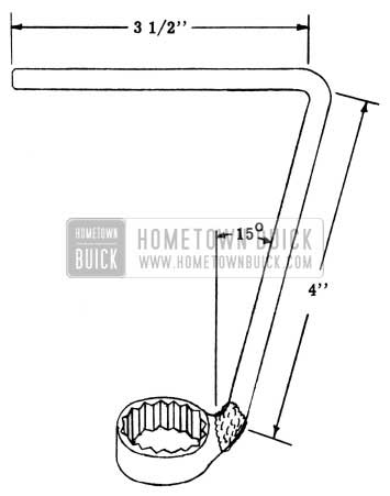
1951 Buick Fender Guard Wrench
ACCESSORY FENDER GUARDS
A change recently made in the method of mounting the front direction signal and parking lamp assemblies, prevents easy removal of the lamps to facilitate accessory fender guard installation.
When installing guards on jobs having the new lamp mounts, we suggest sliding the outside air ventilator tubes to the rear, in order to gain access to the rear of the front bumper guards (bomos). It is necessary to disconnect the defroster blower motor wire before sliding the right hand tube backward.
This procedure should be used on all cars built after approximately April 23rd.
DEFROSTER VALVE “FIT”
1951 SERIES 40
It has been brought to our attention that excessive noise and dust entrance occurs in some 1951 Series 40 jobs, due to a poor fit of the defroster valve when closed. This condition can be eliminated by using the following procedure:
- Make sure that the defroster and ventilator valves are correctly adjusted.
- Remove both flexible tubes from the defroster core outlet housing and valve assembly.
- Remove the defroster core outlet housing and valve assembly.
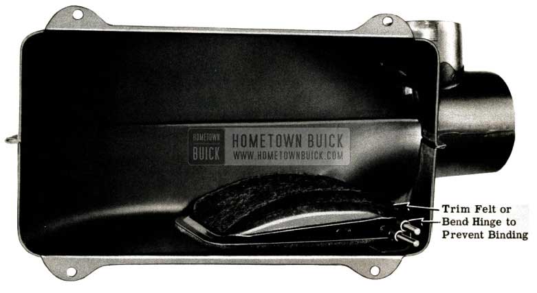
- Apply 1/8″ soft felt to the valve as shown in Figure 36, so that when the valve is closed as shown in Figure 37, the felt will overlap approximately 1/2″.
1951 Buick Defroster Valve Fit
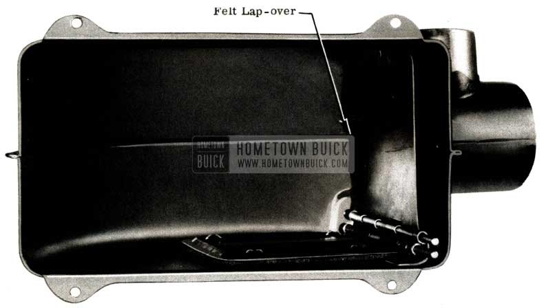
1951 Buick Defroster Valve Felt Lap-Over
It may be necessary to trim the felt or slightly bend the valve hinge to prevent binding and obtain proper fit when the valve is closed.
Note: This is not a campaign item. It should be performed only when customer complaints are received.
SERVICE INSTRUCTIONS FOR THE BUICK SELECTRONIC TUNER
Signal Seeking Tuners are used on Buick “Selectronic” Radios, Models 980899 (1950) and 980980 (1951).
These instructions cover the theory of operation, adjustments, replacements and trouble-shooting procedure for the Signal Seeking Tuner and should prove helpful to dealerships servicing ”Selectronic” radios within their own establishments. Additional “Selectronic” service instructions will be found in United Motors Service Auto Radio Bulletin No. 60-929, which should be used in conjunction with this information.
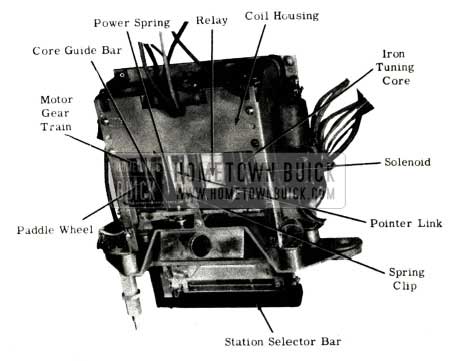
The tuner, when removed from the radio, appears as shown in Figure 38.
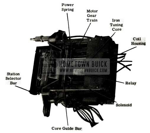
1951 Buick Selectronic Radio Tuner Service
THE SIGNAL SEEKING TUNER
The Signal Seeking Tuner is an electronically controlled automatic tuner by which the operator can change stations by merely depressing a single station selector bar on the radio or an auxiliary foot switch. The seeking operation is a uni-directional sweep of the broadcast band from low to high frequency with a nearly instantaneous return. The tuning mechanism is driven by a spring loaded mechanical motor which is stopped on station by a triggering circuit actuated by voltage developed from an incoming signal.
The number of stations on which the tuner will stop can be regulated by use of the Sensitivity Control. It is a step control which in the extreme clockwise position gives maximum stopping sensitivity, when the antenna is fully extended, while it allows the tuner to stop only on strong local stations when in the minimum sensitivity or extreme counter clockwise position. This control is in the circuit only while the tuner is seeking and does not affect the “on station” sensitivity of the receiver.
THEORY OF OPERATION
MECHANICAL OPERATION
The motive force on the signal sweeping sweep of the tuner is provided by a constant speed spring driven gear train which is regulated by a nylon paddle wheel. This paddle wheel is the end gear in the gear train and acts as an air vane governor which tends to keep the speed constant. The entire gear train is stopped or started by the relay arm engaging or disengaging the paddle wheel. The nearly instantaneous return 1f the pointer and the cocking of the power springs is accomplished by a solenoid which is energized by a cam operated switch. The complete mechanical cycle is developed and outlined below.
SWEEP AND RETURN CYCLE (SEE FIGURE 39)
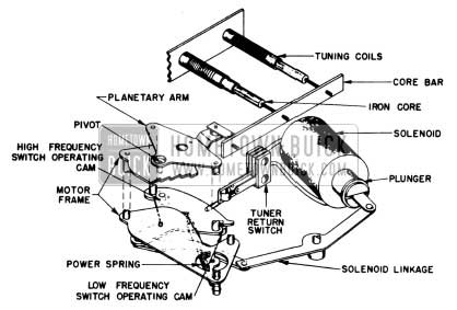
1951 Buick Selectronic Radio Sweep and Return Cycle
One Power Spring, which is fastened to the lower plate of the Planetary Arm, pulls this arm around its pivot. The Planetary Arm is linked to the Core Bar. Thus, as the spring contracts and moves the Planetary Arm it also pulls the core bar and its iron cores from the tuning coils thereby changing the tuned frequency of the radio towards the high end of the broadcast band. After the tuner has swept beyond the top broadcast frequency, the High Frequency Switch Operating Cam on the lower Planetary Arm trips the Tuner Return Switch which in turn energizes the Solenoid and this quickly returns the Planetary Arm to its original position with the cores inserted fully into the coils (low frequency) and the power spring is now under maximum tension. As the Planetary Arm returns, the Low Frequency Switch Operating Cam trips the Tuner Return Switch to its original position thus deenergizing the Solenoid and completing the cycle.
MOTOR AND CONTROL (SEE FIGURE 40)
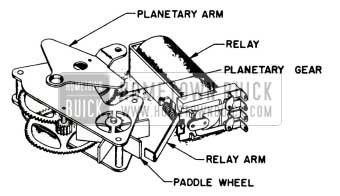
1951 Buick Selectronic Radio Tuner Motor and Control
The Power Spring tends to move the Planetary Arm about its pivot point thereby starting the Planetary Gear and its meshed train in motion. This motion is transferred through the gear train to the Paddle Wheel which acts as an air vane governor keeping the motion at a constant speed. This movement of the Planetary Arm is then controlled by merely freeing or blocking the Paddle Wheel with the Relay Arm. Thus, the movement of the Planetary Arm which moves the tuning cores is started or stopped by the action of the Relay Arm.
MANUAL TUNING GEAR OPERATION (SEE FIGURE 41)
1951 Buick Selectronic Radio Sweep and Return Cycle
Manual tuning is accomplished by turning the Manual Control Shaft which turns the Worm Gear in its bracket. The Worm Gear is meshed with the Manual Drive Gear which in turn is meshed with the Planetary Pinion Gear. During manual tuning the Paddle Wheel is held in place by the Relay Arm and this Pinion Gear is not free to rotate, thus effectively locking the Planetary Arm to the outer edge of the Manual Drive Gear. Therefore as the Manual Drive Gear turns, the Planetary Arm moves in unison with it and varies the frequency of the tuner by varying the position of the iron cores in the tuning coils. (Notice that when the set is being tuned automatically and the Paddle Wheel is rotating the Manual Drive Gear is held securely in place by the Worm Gear while the Planetary Pinion Gear “walks around” the periphery of the Manual Drive Gear thereby causing the Planetary Arm to move and change the position of the tuning cores.)
POINTER AND CORE BAR LINKAGE (SEE FIGURE 41)
The second power spring is shown in this view. It has a dual purpose, serving both as a power spring and an anti-backlash spring. The primary linkage is from the tuner frame to the Lever Arm which is securely staked to the Bell Crank. At the Bell Crank the linkage splits, with one arm linked to the core bar at the extreme left end, and the other arm linked to the pointer. Thus, this spring helps pull the core bar in the high frequency direction when it is free to move and provides a spring loaded linkage between the core bar and the pointer preventing any tendency for backlash.
CLUTCHING OPERATIONS (SEE FIGURE 42)
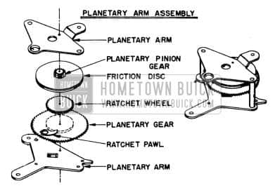
1951 Buick Selectronic Radio Clutching Operations
The Ratchet Pawl and Wheel are used so that the Solenoid can cock the power springs without running the entire gear train in the reverse direction during the return sweep. Notice that the Ratchet also is used when the dial pointer has reached the high end of the band while tuning manually. Then the Planetary Arm has reached the end of its tuning arc and so the planetary pinion tends to be rotated by the Manual Drive Gear (see Fig. 40) .This turns the Ratchet Wheel out of the Pawl and allows the pinion gear to turn freely without exerting further force on the Planetary Arm and thereby eliminates any possible damage to the mechanism.
The purpose of the Friction Disc is to prevent damage to the mechanism when manually tuned past the low frequency stop. This is accomplished because the disc slips before excessive pressure is exerted when the Pinion Gear tends to rotate the Planetary Gear.
TUNER SWEEP CYCLE OUTLINE (FIGURE 43)
1951 Buick Selectronic Radio Tuner Sweep Cycle Outline
- Tuner is started by removing Relay Arm from Paddle Wheel.
- Spring driven gear train begins to sweep. (Fig. 40)
- Planetary Arm moves. (Fig. 39)
- Tuning cores are moved toward higher frequency by core bar linkage to Planetary Arm.
- Spring loaded dial pointer scans dial. (Fig. 41)
- Signal actuates relay causing arm to stop paddle wheel.
- Gear train stops. (Fig. 40)
- Planetary Arm is stopped.
- Core bar movement is stopped.
- Dial pointer sweep is stopped.
- When tuner reaches high end of dial after last stop.
- The High Frequency Switch Operating Cam trips Tuner Return Switch. (Fig. 39)
- Solenoid is energized.
- Plunger is pulled into the Solenoid.
- Planetary Arm and pointer are returned to low end of dial.
- The Low Frequency Switch Operating Cam trips the Tuner Return Switch in the opposite direction. (Fig. 39)
- The Solenoid is de-energized and the sweep starts from the low frequency stop.
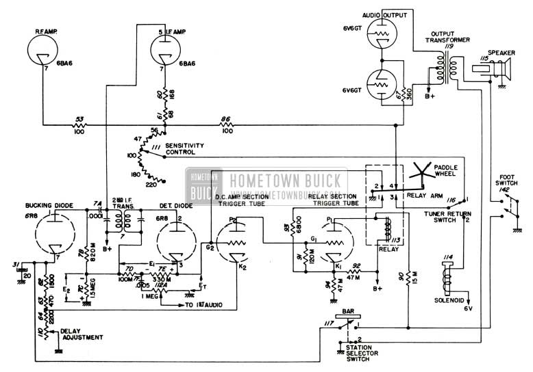
ELECTRICAL OPERATION
The purpose of the electrical components associated with the tuner is to control the relay so the operator may start the tuner sweeping cycle by merely depressing the station selector bar and so that the sweeping operation will continue until a signal is received. At that time it is the function of this circuit to accurately tune to the frequency of the selected station. It also provides the necessary conditions to keep the tuner on the station until a change is desired. The operational cycle of the electronic control system of the signal seeker tuner is outlined below.
THE ELECTRICAL CYCLE OUTLINE (FIGURE 44)
1951 Buick Selectronic Radio Electrical Cycle Outline
- Starting the Tuner Seeking (Energizing the Relay) – The Station Selector Bar (117) or Foot Switch (142) is momentarily depressed.
- Contact #2 of the Station Selector Switch opens first, ungrounding secondary of the output transformer therefore muting the set as contact #1 closes.
- Contact #1 closes and provides a circuit from B+ through the relay winding, the 13,000 ohm resistor (90), the Selector Switch contacts, and the delay circuit resistor network to ground.
- The current through this c11’cult energizes the Relay and removes the Relay Arm from the Paddle Wheel-thus starting the tuner, opening contacts #2 and #4, and grounding relay contacts #1 and #3.
- Keeping the Tuner Seeking after the Selector Bar is released (Keeping the Relay Energized).
- Relay contact #3 is closed providing a path to ground for the cathodes of the R.F., I.F. and audio amplifier tubes. This path is through the Sensitivity Control so the sensitivity of the set can be controlled during the sweeping operation.
- Relay contact #1 is grounded thus lowering the cathode to ground resistance of the Relay Section of the Trigger Tube by putting the 6,800 ohm resistor (93) in parallel with the 47,000 ohm cathode resistor (94).
This causes a lowering of the cathode voltage thereby causing an increased plate current flow which is sufficient to keep the relay energized and the tuner seeking.
- Stopping the Tuner on Station with an Incoming Signal (De-energizing the Relay).
- A voltage from the incoming signal is developed in the primary and secondary of the 2nd I.F. transformer (7).
- The voltage in the secondary of the I.F. coil is recified by the Detector Diode developing a D.C. voltage across the 330,000 ohm resistor (7E).
- The voltage in the primary of the I.F. coil is recified by the Bucking Diode developing a D.C. voltage across the 1.5 megohm resistor (7C).
- The voltage developed by the Bucking Diode across the 1.5 megohm resistor (7C) opposes the voltage developed by the Detector Diode across the 330,000 ohm resistor (7E). The resultant voltage is applied to the grid of the D.C. Amplifier Section of the Trigger Tube. This triggering voltage gives a substantially constant tuning accuracy for all signals.
- When the resultant triggering voltage on the grid of the D.C. Amplifier becomes positive it causes the tube to conduct.
- The plate current flow in the D.C. amplifier section develops a biasing voltage across the 120,000 ohm resistor (91) which is between grid and cathode of the Relay Section of the Trigger Tube, making the grid more negative than the cathode thus reducing the plate current.
- The decrease in plate current flow causes the relay to be deenergized and the Relay Arm again engages the Paddle Wheel thereby stopping the tuner sweep on a station, opening contacts #1 and #3 and grounding relay contacts #2 and #4.
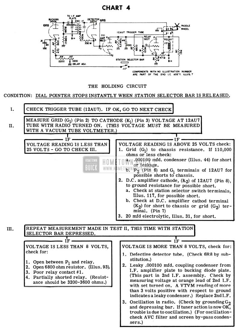
- Holding the Tuner on Station until a new Station is Desired (Holding the Relay De-energized):
- Relay contact #1 is opened, ungrounding the 6800 Ohm Resistor (93), thus preventing any appreciable current flow in the relay.
- Relay contact #4 is grounded and this grounds the cathode circuits of the R.F., I.F. and audio amplifiers effectively by-passing the sensitivity control (111), which is now ungrounded, and leaving the set at normal sensitivity.
- Relay contact #2 is grounded thereby grounding out the grid of the D.C. Amplifier. Any voltage now developed across the 330,000 ohm resistor (7E) keeps the Bucking Diode from conducting by applying a negative voltage to its plate and the Detector Diode now functions as a conventional detector.
THE TUNER DETECTION CIRCUIT (SEE FIGURES 44 AND 45)
1951 Buick Selectronic Radio Tuner Detention Circuit
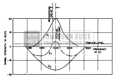
The purpose of the tuner detection circuit is to take input signal voltages of varying strength and trigger the relay tube so that the tuner will stop accurately on the station frequency. A positive voltage developed by the signal on the grid of the D.C. Amplifier Section causes the tuner to trigger and stop. This is accomplished by using the Detector Diode and Bucking Diode to develop voltages of opposite polarity (E1 and E2) between grid and ground of the D.C. Amplifier Section of the Trigger Tube, thus effectively applying the algebraic sum of these voltages (E1) to this signal grid. (Note that contacts #2 and#4 of the relay are open.) These relative voltages plotted against frequency are shown in Fig. 8 using a station frequency of 1200 K.C. Notice that the response curve of the voltage (E2) across the 1.5 megohm resistor (7C) is broader and not as large as the voltage (E1) developed across the 330,000 ohm (7E) detector load. This is because the detector voltage has benefit of one more tuned circuit which gives the narrower curve. Also there is a positive voltage appearing at the cathode of the Bucking Diode which will have the effect of lowering the voltage (E2) across the 1.5 megohm resistor (7C) because it will introduce a delay before the Bucking Diode will begin to conduct. This delay can be controlled by the Delay Adjustment in the cathode of the Bucking Diode. This Delay Adjustment also controls the trigger level so that the mechanical delay is compensated for and the tuner stops exactly on station. It is a factory adjustment and SHOULD not be adjusted unless it is proven faulty.
Since the two diodes obtain their voltages from the same incoming signal, the strength of both voltages will vary directly with the strength of the incoming signal. Therefore, while they both rise and fall with variation in signal strength, their difference (Et), which is effectively the trigger pulse, will tend to remain constant. Thus, a station will be tuned in with the same degree of accuracy whether it is a strong or weak signal.
TUNER MUTING (SEE FIGURE 44)
Various methods of muting are employed in the signal seeker tuner operated radios. To prevent a click in the speaker as the station selector bar energizes the relay, the output transf0rmer circuit is opened (contact # 2 of Station Selector Switch (117), before contact #1 is made. Or, in the case of the foot switch, the speaker voice coil is grounded and the set muted before the relay energizing contact is made.
The receiver is also muted when the solenoid is energized during the return cycle of the tuner. This is accomplished because when the tuner return switch (116) is mechanically tripped to position #2 it ungrounds the Sensitivity Control which is the cathode return for the R.F., I.F. and audio amplifier tubes thus momentarily disabling the set.
SENSITIVITY CONTROL
The sensitivity control is a step resistor which is inserted into the cathodes during the tuning sweep when relay contact #3 is grounded and is the means by which the operator controls the number of stations on which the tuner will stop.
ADJUSTMENTS
All adjustments on Signal Seeking Tuners are made accurately at the factory and do not require further adjustment unless it is definitely proven they are wrong or tuner parts are replaced. These adjustments are readily accessible and can be made without removing the tuner from the radio.
All adjustments are made with the antenna disconnected from the radio. All adjustments can be reached by removing the front and rear covers of the radio and the adjustment cover on the top of the radio. The correct procedures for making these adjustments are as follows:
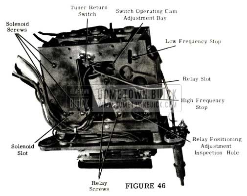
1951 Buick Selectronic Radio Signal Seeking Tuner Adjustment
SOLENOID POLE PIECE ADJUSTMENT (FIGURE 47)
1951 Buick Selectronic Radio Selenoid Pole Piece Adjustment
This adjustment should be made whenever the Solenoid or Solenoid Plunger is replaced. Its purpose is to obtain the correct amount of force from the Solenoid and to prevent the Solenoid Plunger from sticking.
- With a screwdriver back the Solenoid Pole Piece out of the Solenoid.
- Bottom the Solenoid Plunger in the Solenoid. The plunger is bottomed when the ”C” washer collar on the plunger hits the frame of the Solenoid.
- Screw the Solenoid Pole Piece into the Solenoid until it just touches the plunger.
- Back the pole piece off exactly 11/2 turns.
- Tighten the hex locking nut and seal with glyptal or shellac.
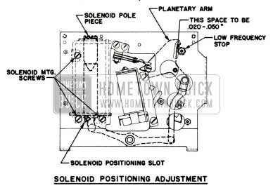
SOLENOID ADJUSTMENT (FIGURE 47)
The Solenoid adjustment should be made whenever solenoid or Solenoid plunger is replaced. Its purpose is to provide the correct amount of solenoid plunger movement to move the tuner to the low frequency end of the broadcast band.
- With the radio turned off, connect a jumper wire across the 0.5 mfd condenser, Illustration 47, on the cold side of the Solenoid. This is the only paper condenser found on the tuner.
- Turn the radio on. (This energizes the Solenoid.)
- Energize the Relay by momentarily depressing the Station Selector Bar.
- Loosen but do not remove the three solenoid mounting screws.
- Using a screwdriver in the Solenoid Positioning Slot, turn the screwdriver and move the Solenoid until there is a 0.005 to 0.020 inch gap between the Planetary Arm and its Low Frequency Stop.
- Tighten the three Solenoid Mounting Screws.
- Turn the radio off and remove the jumper wire from the condenser.
RELAY ADJUSTMENT (FIGURE 48)
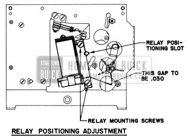
1951 Buick Selectronic Radio Relay Adjustment
This adjustment should be made whenever the relay is replaced. This is the only adjustment of the relay that should be attempted in the field. The adjustment of the relay is to position the relay arm to have the correct engagement and clearance with the gear train paddle wheel.
- With the radio turned off, connect a jumper wire across the 0.5 mfd condenser, Illustration 47, on the cold side of the Solenoid. This condenser is found on the tuner.
- Turn radio on. {This energizes the Solenoid.)
- Energize the Relay by momentarily depressing the Station Selector Bar.
- Loosen but do not remove the two Relay Mounting Screws.
- Using a screwdriver in the Relay Positioning Slot, turn the screwdriver and move the relay until there is a gap of approximately 0.030 or 1/32 inch between the top of the Relay Arm and the tip of the blades on the Paddle Wheel.
- Tighten the two Relay Mounting Screws.
- Turn the radio off and remove the jumper wire from the condenser.
SWITCH OPERATING CAM ADJUSTMENT (FIGURE 49)
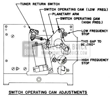
1951 Buick Selectronic Radio Switch Operating Cam Adjustment
This adjustment should be made whenever the Motor Gear Train or the Tuner Return Switch is replaced. Its purpose is to set the timing of the Tuner Return Switch.
- With the radio turned off, insert a 0.060 inch feeler gauge through the slot against the Low Frequency Stop. Number 14 bare wire is satisfactory gauge.
- Position the Planetary Arm against the feeler gauge. This can be done with the manual tuning control (tuning cores all the way in the coils).
- With a small screwdriver, move the Low Frequency Switch Operating Cam to a position furthest from the Tuner Return Switch.
- Trip the Tuner Return Switch so that its operating arm is toward the cam.
- Turn the Low Frequency Switch Operating Cam in a _counter clockwise direction until it trips the switch.
- Insert a 0.060 inch feeler gauge through the slot against the High Frequency Stop.
- Position the planetary arm against the feeler gauge. CAUTION: DO NOT USE DIRECT FORCE TO MOVE THE PLANETARY ARM. The Planetary Arm can be positioned by using the manual tuning control.
- Turn the Switch Operating Cam to the position furthest from the Tuner Return Switch if this has not already been done.
- Trip the Tuner Return Switch so that its operating arm is towards the cam.
- Turn the High Frequency Switch Operating Cam in a clockwise direction until it trips the Tuner Return Switch.
CATHODE DELAY ADJUSTMENT
This adjustment controls the tuning accuracy of the radio and is carefully adjusted at the factory. It should not be made unless the part is replaced. It is adjusted as follows:
- With the antenna disconnected turn the radio on and allow it to warm up; then depress the station selector bar.
- Adjust the input voltage to the radio to exactly 6 volts at the “A” connector or the spark plate.
- Connect a meter from the cathode of the D.C. amplifier section of the trigger tube (pin 8 of the 12AU7 tube) to chassis and adjust the cathode delay rheostat, illustration 110, so the meter reads the voltage specified under “Adjustment Procedure” in UMS Auto Radio Bulletin 6D-929.
REPLACEMENTS
This tuner has been designed to provide a maximum of servicing efficiency. All service parts have been made very accessible and easy to replace. The wiring to the tuner has been made long enough so that the tuner can be dismounted from the radio case and worked on without disconnecting any leads. (NOTE: It may be necessary to remove some connections of bond straps.) For most replacements such as the relay, the tuner switch, etc., no special instructions other than being sure the proper adjustments are made are necessary. However, to facilitate fast replacement of some parts, the following instructions are included:
SOLENOID OR SOLENOID PLUNGER REPLACEMENT (FIGURE 47)
- Remove the radio rear cover and adjustment cover. (Note: It may be necessary to remove the front cover.
- Remove the three solenoid mounting screws found on the top of the tuner.
- Disconnect the two leads to the solenoid.
- Remove the solenoid and bracket from the rear of the tuner. (It will be necessary to disconnect one lead of a 0.5 mfd condenser on some radios to give sufficient clearance.)
- Remove the solenoid plunger from its linkage by removing the spring clip holding this linkage to it.
- Place the plunger in the solenoid and make the Solenoid Pole Piece Adjustment.
- Install the solenoid plunger and solenoid in the tuner.
- Fasten the solenoid plunger to its linkage with the spring clip.
- Solder the leads to the terminals from which they were removed. (if the 0.5 mfd condenser lead was removed, solder it in place.)
- Mount the solenoid to the tuner with the three screws and make the solenoid adjustment.
STATION SELECTOR SWITCH REPLACEMENT (FIGURE 50)
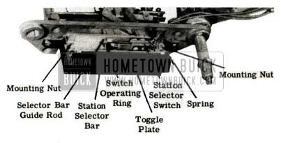
1951 Buick Selectronic Radio Station Selector Switch Replacement
- Remove the escutcheon from me front of the radio.
- Remove the Station Selector Bar and switch assembly which is held in place with two screws through the mounting plate.
- Remove the switch and disconnect the leads.
- Connect the leads to the new switch and assemble to mounting plate.
- Adjust the position of the Switch Operating Ring so that it overtravels the opening and closing of the switch contacts in both directions about .030 or 1/-32 inch. This adjustment is made by inserting a screwdriver in the slot on the ring and sliding on the selector bar shaft.
- Return the selector bar and switch assembly to the radio and fasten with the two screws.
STATION SELECTOR BAR REPLACEMENT (FIGURE 50)
- Remove the station selector bar and switch assembly from the radio as described in Steps 1 and 2 of Station Selector Switch Replacement.
- Remove the small “C” washer from the end of the station selector bar shaft.
- Remove the two springs that hold the station selector bar and toggle plate to the mounting plate.
- Assemble the new station selector bar and toggle plate with the two springs to the mounting plate as shown.
- Place the “C” washer on the shaft and secure.
- Adjust the position of the switch operating ring as described in Step 5 of Station Selector Switch Replacement.
- Return assembly to the radio and mount with the two screws.
MOTOR GEAR TRAIN REPLACEMENT (FIGURE 51)
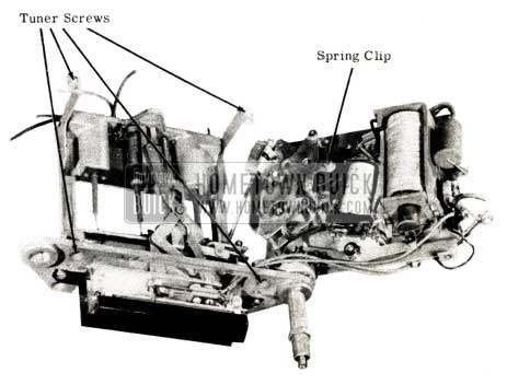
1951 Buick Selectronic Radio Motor Gear Train Replacement
- Remove the front and rear cover of the radio.
- Dismount the tuner from the case and move it out of case far enough so that it can be worked on.
- Divide the tuner into two parts by:
- Removing the spring clip holding the gear train planetary arm to the core guide bar linkage.
- Removing the four tuner assembly screws.
- Separating the two halves of the tuner.
- Remove the worm gear and bracket from the gear train.
- Disconnect the motor gear train from the solenoid plunger linkage by removing the spring clip holding them together.
- Remove the three nuts mounting the motor gear train.
- Mount the new motor gear train to the tuner with the three nuts.
- Connect the gear train to the solenoid linkage with the spring clip.
- Remove the screw holding the manual gear of the gear train in position and mount the worm gear and bracket to the gear train. Be careful to get good gear mesh and do not lose the anti-squeak spring on the worm gear bracket.
- Reassemble the tuner and make the Switch Operating Cam Adjustment.
THE TROUBLE SHOOTER’S GUIDE
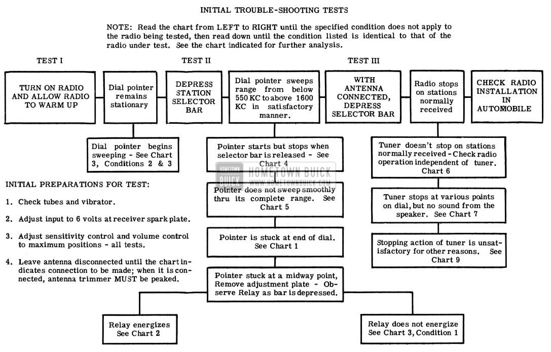
To facilitate rapid diagnosis of troubles which may develop in the Signal Seeking Tuner, those most likely to occur have been classified and listed in a troubleshooting chart. Three fundamental tests which are easily made on the radio are the basis for this chart. The normal indication for each test is shown just to the right of the test block in solid lines and if the indication is normal the next basic test should be made. However, if the normal indication does not apply to the radio under test, the various abnormal indications that could result from the check are shown in solid line blocks below the normal condition.• When the block which applies to the radio being checked is reached, a chart which will contain a simplified partial schematic will be referred to. The checks necessary to isolate the defective components will also be included in this chart and components are assigned illustration numbers which are the same as those in bulletin 6D-929. Thus, through the use of these charts, the vast majority of the troubles can be isolated in a very short period of time.
INITIAL TROUBLE-SHOOTING TESTS
NOTE: Read the chart from LEFT to RIGHT until the specified condition does not apply to the radio being tested, then read down until the condition listed is identical to that of the radio under test. See the chart indicated for further analysis.
1951 Buick Selectronic Radio Troubleshooting Tests
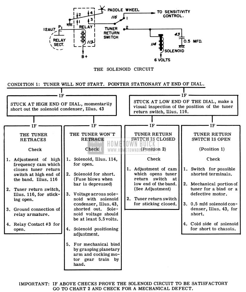
1951 Buick Selectronic Radio Selenoid Circuit
1951 Buick Selectronic Radio Tuner not Starting
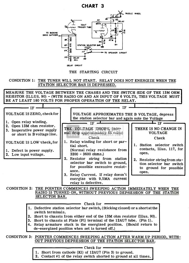
1951 Buick Selectronic Radio Starting Circuit
1951 Buick Selectronic Radio Holding Circuit
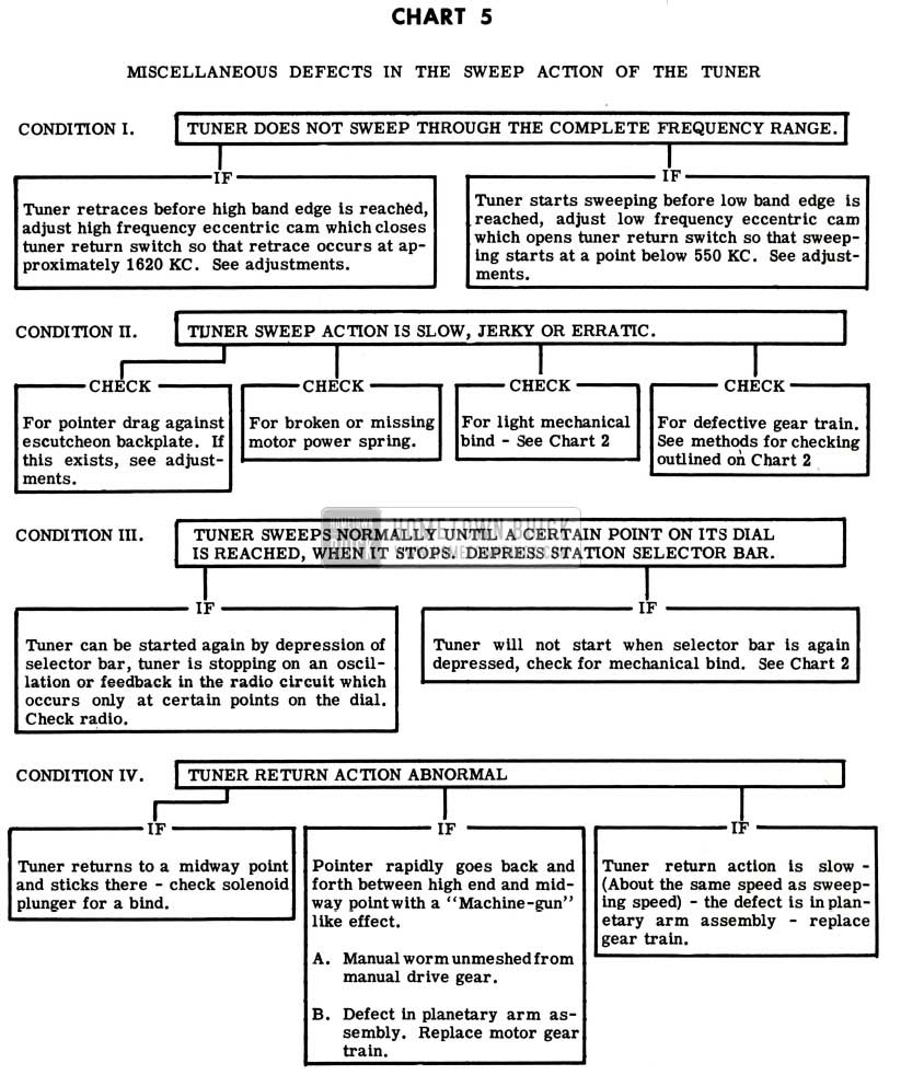
1951 Buick Selectronic Radio Defects
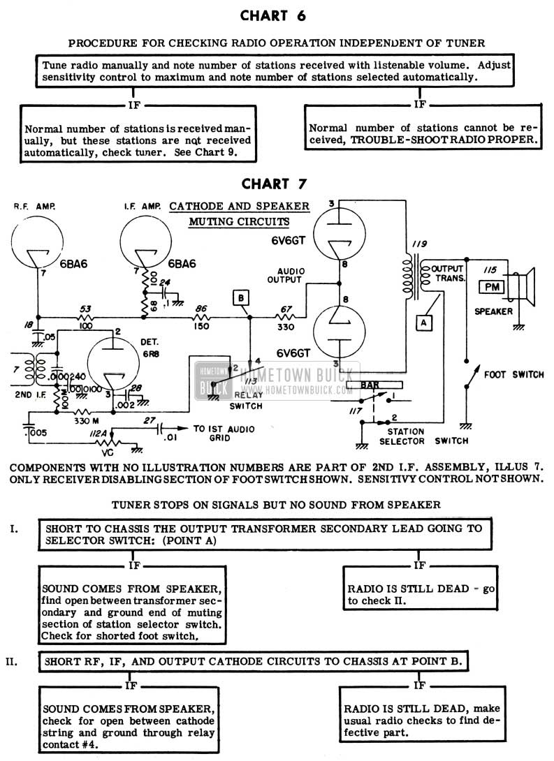
1951 Buick Selectronic Radio Checking Procedure
1951 Buick Selectronic Radio Tuner Station Problem
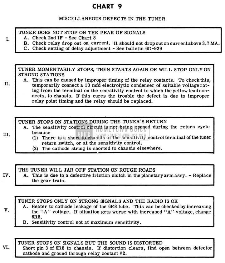
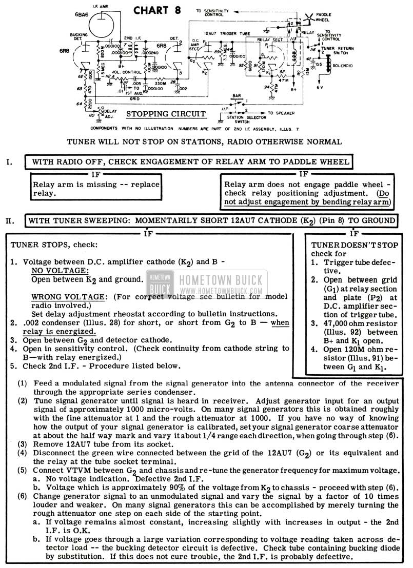
1951 Buick Selectronic Radio Tuner Defects
RANCO VALVE CHATTER
1951 ALL SERIES
We have received several owner complaints of excessive Ranco Valve “chatter” on 1951 models, which is apparently not corrected by installation of a new valve.
This condition can be caused by incorrect direction of water flow through the valve. The flow should be from the underseat heater to the valve inlet (lower connection) and then from the valve outlet (upper connection) to the defroster inlet (lower connection).
When complaints of this nature are received, we suggest that the car be checked for correct “hookup” before any Ranco Valve replacement is made.
HEATER OPERATION
When handling complaints of poor heater or defroster performance, the following items should always be checked and corrected if necessary:
- Ventilator Valves For Proper Sealing
Ventilator valve control wires should be adjusted so that the valve closes before the knob hits the instrument panel. This adjustment is made in clamping the cable sheath at the valve. Loosen the cable clamp. Then position the cable so that the valve is closed tight when the knob has approximately 1/16 clearance from radio speaker grille. Retighten clamp.
- Cold Air Leaks Through Dash
Any cold air leaks through the dash, such as at the steering column jacket, should be plugged.
- Heater Temperature Control Lever and Wire Adjustment
Check the Heater Temperature Control Lever assembly for proper control wire adjustment. The valve itself should act as a stop on both ends of control lever travel. To adjust properly, loosen clamp at temperature control valve. Adjust the control wire sheath at control lever assembly to permit maximum travel of lever. Set lever at “off” position, under the letter “0”, approximately two notches from extreme right end of travel. With temperature control valve in locked off position (rotated clockwise until cam locks against roller), assemble control wire to valve and clamp in place.
- Heater Air Outlets For Floor Mat Interference
Inspect front and rear floor mat for proper fit at underseat heater air outlets. The mat may have shifted or be improperly installed blocking off the air outlet.
- Heater Hot Water Hose For Proper Connections
Check the heater hot water hose for proper connections. On Dynaflow jobs the water should flow from the Tee connection to the underseat heater; from underseat heater to the temperature control valve (lower connection); from temperature control valve to defroster inlet (lower connection) and return to water pump suction (center nipple at water pump). On Synchromesh jobs the flow is from thermostat housing to underseat heater to temperature control valve to defroster to water pump suction. Note that reversing the direction of flow through the temperature control valve will cause excessive “chattering” or “buzzing”. The lower connection is the inlet and upper the outlet.
- Radiator Pressure Cap
The radiator pressure cap seal may be defective, the cooling system normally runs under 4 to 7 psi pressure. Loss of pressure may cause a loss of 10 to 15 degrees water temperature. The seal seat in the radiator filler neck should be smooth and free of dirt or other foreign material. The rubber seal in the pressure cap should also be smooth and free of defects.
- Engine Thermostat
The engine thermostat directly controls water temperature. Production thermostats normally open from 1480 to 1550F. Thermostats can be checked by heating in a container filled with water and determining the temperature at which the valve starts to open with a thermometer. The water must be agitated and the point at which valves begin to open is determined by tapping on the valve plate,
- Owner Driving Habits
Dynaflow owners should be warned against racing of the engine with the transmission in drive range and brakes locked in attempting to obtain quick warm-up. This may cause excessive localized heat at the transmission oil cooler resulting in vapor lock and consequent damage to the transmission. Never install alcohol with 180° thermostat as this may result in the same transmission difficulties.
RADIO VIBRATOR DAMAGE
“CAUTION: It is possible to damage certain parts of the radio if the starter is engaged while the radio is on. As an added precaution, do not attempt to start the engine unless the radio is off. The radio switch may be turned on after the engine is running.”
It is advisable to relay the above information to all present owners whenever possible and it should be emphasized when new car delivery is made.
This caution is prompted by the fact that it is possible to render the vibrator inoperative if the radio is “on” when the starter is engaged. In view of present material restrictions, new vibrators may become extremely difficult to obtain.
Leave A Comment
You must be logged in to post a comment.