ENGINE FUEL AND EXHAUST SYSTEMS
FUEL AND VACUUM PUMP
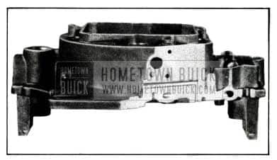
A completely redesigned fuel and vacuum pump assembly (Figure 6) is used on Series 40 and 50 cars.
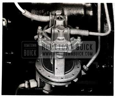
1952 Buick Fuel Pump Installed
The pump is mounted on the right side of the crankcase in a further forward position, which allows the fan blast to assist in preventing overheating and vapor lock. The drive is by a rocker arm off the camshaft as in previous models.
The outstanding feature of the new pump is the double-acting vacuum section which displaces air from both the top and bottom sides of the vacuum diaphragm. This increases windshield wiper efficiency approximately 15% under full throttle, low speed conditions.
The fuel and vacuum diaphragm pull rods have bellows type seals which eliminate the wearing action present with the old slide type seals, and lessen the possibility of oil leakage.
The fuel section of the pump is fitted with a hexagon head plug, adjacent to the inlet, which has a sump area and cylindrical filtering screen.
The Series 70 fuel and vacuum pump has been modified so that the vacuum section provides the same double-acting feature of the Series 40-50 pump. No change has been made in the fuel section of the 70 pump.
FOUR BARREL CARBURETOR
The four barrel carburetor used on all 1952 Series 70 cars consists of two dual carburetors mounted back-to-back. This development increases the power output of the engine approximately 10% at high speeds.
As in the past, two makes of carburetors will be used in production as follows:
Carter Model WCFB – 894S
Stromberg Model 4AUV – 267
Essentially, the front or primary carburetor serves the same functions as the former carburetors. It has an idle system with mixture quality adjustment and speed adjustment, main metering system with vacuum controlled enrichment device for full throttle power, automatic choke, fast idle control, a port for actuating the vacuum advance of the distributor, a throttle lever, and a starting switch. The second or secondary, carburetor serves as a booster. It has an idle system and a main metering system for wide open throttle operation, although the idle is not adjustable. The secondary throttle is actuated by the primary throttle lever by means of a link and pickup lever.
Each unit of the carburetor has a separate float chamber with two interconnected floats actuating a float needle valve mounted in each chamber. These floats hold the fuel level at the nozzle outlets constant so that flooding or leaning cannot occur on grades. One gasoline inlet feeds both chambers through a channel in the float chamber cover.
Above the main throttle valve C (Figure 7) in the secondary carburetor is an auxiliary throttle valve D which is allowed to function when the main throttle valve is opened.
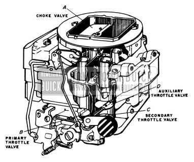
1952 Buick Carburetor Main Throttle Valve
This auxiliary valve D is an unbalanced valve held shut by means of a weighted lever. It controls the air and fuel flow through the secondary carburetor according to engine requirements and functions only after the main throttle valve has opened.
With reference to the four cut-away views shown in Figure 8, the throttle valve positions, choke valve positions, and auxiliary throttle valve locking linkage are illustrated for the four engine conditions.
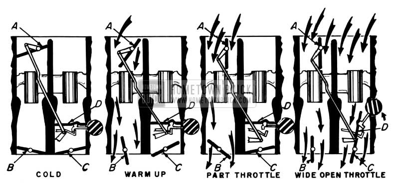
1952 Buick Carburetor Main Throttle Valves
For the cold engine, the choke valve A, primary throttle valve B, secondary throttle valve C, and auxiliary throttle valve D are all closed. When the choke valve A closes, a connecting lever locks the auxiliary throttle valve D in the closed position.
During the warm up period, the choke valve is partially opened, but not far enough to release tile locking linkage to the auxiliary throttle valve.
The secondary throttle valve can open, but the secondary carburetor does not function since the auxiliary throttle valve is closed and locked.
For part throttle operations, the choke valve is fully opened, the auxiliary throttle valve is unlocked, and the secondary carburetor is ready to function according to engine requirements.
A link and blocking cam actuated by the automatic choke prevents the auxiliary throttle valves from opening until the choke is nearly wide open. Without this, the wide open throttle operation during warm up would be very lean as no enrichening device is provided on the secondary carburetor. An automatic choke cannot readily be used on the secondary unit unless the choke valve is partially opened by some means so that the depression at the nozzle is low enough to prevent it feeding fuel until the secondary throttle starts to open.
The horsepower increase is accomplished by lowering the restriction through the carburetor, which improves the volumetric efficiency of the engine. The ability to deliver more mixture to the combustion chambers at high speeds increases the power output. About the same output could be obtained by installing a larger dual carburetor. The larger carburetor however, would be too large at low and moderate engine speeds and would actually cause a loss in power at these speeds. By using the four-barrel carburetor, the primary carburetor
can be tailored to fit the engine requirements at the lower speeds and, by using the auxiliary valve, the secondary carburetor can be cut in to get nearly ideal results for maximum power output throughout the engine speed range.
During part throttle operation, up to 80 MPH, the fuel and air supply is metered by the primary carburetor only. The accelerator pedal is connected to the primary throttle lever of the carburetor. When the primary throttle is about one -half open (about 80 MPH) a pick up lever engages a loose lever on the shaft and by means of a link and lever starts to open the secondary carburetor. The geometry of the linkage is such that the opening rate of the secondary is about twice that of the primary, so that when the primary is wide open, the secondary also is wide open. The reason for only having a metering system in the secondary, which will deliver a fu11 power mixture, is that above 80 MPH it is not possible to run on the lean mixture used at- lower speeds. Above this speed the primary carburetor also delivers the richer mixture required for full power.
An idle system is used in the secondary carburetor which delivers a portion of the fuel required when the engine idles. At high speeds, on part throttle, it assists in smoothly bringing in the secondary carburetor. No lean spot develops before its main metering system starts to function. At lower speeds, on part throttle, the idle system in the secondary also delivers nearly the same amount of fuel as it does at idle. This helps to maintain the correct fuel level in the secondary bowl by using fuel faster than the normal “creep” in level caused by vibration of the float mechanism.
The idle system of the secondary4 is fixed (no adjustments). The throttle valves close up against the throttle bore wall reducing the air flow to a minimum. The angle of the throttle valves is such that the valves will not wedge and stick shut.
By having the primary and secondary throttle close together, it is possible to adjust the mixture quality at idle on the primary unit, with a fixed fuel discharge on the secondary, and still affect all cylinders on each manifold branch equally. This could not .be done with the 1941 and 1942 compound carburetion system.
By placing the auxiliary throttle above the main secondary throttle, it is in a low suction location and does not increase the leakage into the manifold. Any leakage through its bearing still has to pass the main throttle valve.
The idle system used on this four-barrel carburetor has a much lower minimum air flow than the 1941-1942 compound carburetion system. This means that the engine idle speed can be maintained as low as the speeds we have been using for years, without getting roughness and missing.
By using the primary carburetor only on part throttle operation, a slight gain in fuel economy is possible. The higher velocity through a smaller carburetor usually permits more accurate fuel metering. Essentially it is not different from “economy set ups” used by various manufacturers which, among other things, also includes the use of a pinched down carburetor.
The carburetor is vented internally in the air horn with the vents located so that they cannot blank off on turns and grades during acceleration or when stopping. The vents are also located and shaped so that the metering is not affected by changes in air cleaner restriction. It can be run without an air cleaner and still maintain correct metering.
As previously stated, the four-barrel carburetor increases the horsepower output 10%. It is one package, longer, but not higher or wider than a standard dual carburetor. It requires no more attaching parts than a dual. The number of adjustments are the same as a standard dual and are made in the same manner. It will idle and perform as smoothly as any dual carburetor.
CARBURETOR SPECIFICATIONS
CARTER
Carburetor Model WCFB
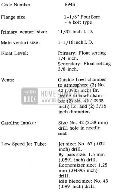
1952 Buick Carter Carburetor Specifications
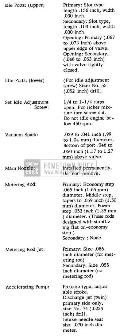
1952 Buick Carter Carburetor Specification
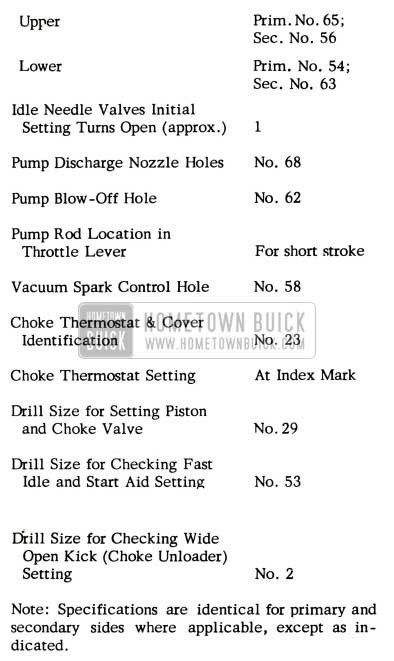
STROMBERG
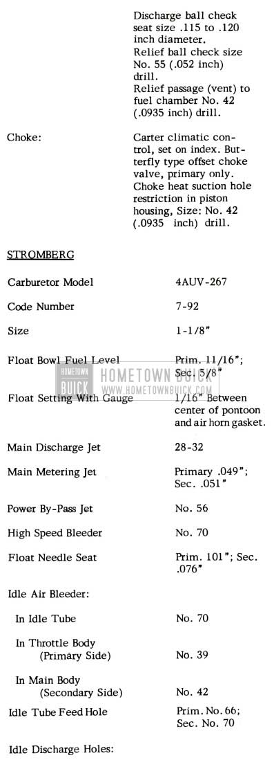
1952 Buick Stromberg Carburetor Specifications
1952 Buick Stromberg Carburetor Specification
Note: Specifications are identical for primary and secondary sides where applicable, except as indicated.
SERIES 70 MANIFOLDS
Series 70 manifolds have been redesigned to accommodate the four barrel carburetor and have been simplified so that the entire assembly now consists of four instead of the former five units. The valve body and center section of the exhaust manifold are cast as a unit, thus eliminating the joint in this location and the subsequent possibility of leakage.
SERIES 70 MUFFLER
The 1952 Series 70 mufflers have a double wrapped outer shell which eliminates noise caused by vibration of the side walls.
CARTER 894-S CARBURETOR
1952 SERIES 70
The Caner Carburetor Corporation is releasing a special service kit for use in modifying 1952 Code 894-S, Four-Barrel carburetors that have a tendency to stall or hesitate on acceleration after starting a warm engine. This kit, Part No. 75-847U contains the following items:
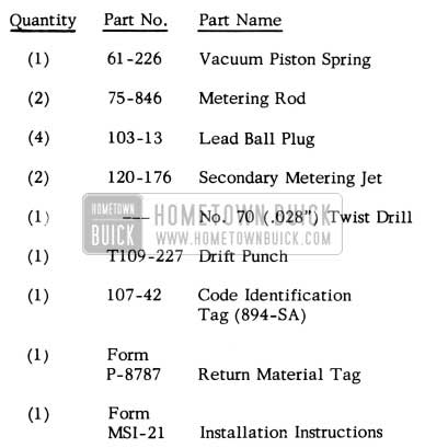
1952 Buick Carter Carburetor Part Numbers
The modification procedure, using Kit No. 75-847U is as follows:
- Remove carburetor assembly from engine.
- Remove air horn attaching screws and dust cover. Note that one (1) screw is located inside the metering rod dust cover housing.
- Remove choke connector rod, throttle connector rod and metering rods.
- Carefully remove air horn assembly with remaining parts attached by lifting straight up from carburetor bowl.
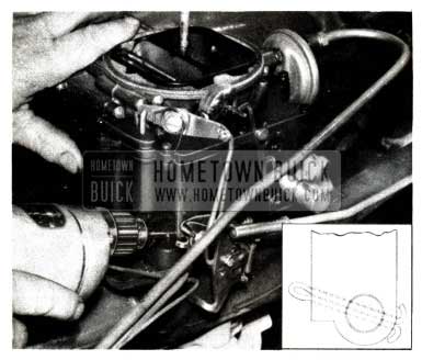
- Using drift punch supplied in kit, drive the four restriction bushings into the anti-percolating passages until punch shoulders against casting – NO FURTHER. This operation is shown in Figure- 9, which pictures one of the secondary passages.
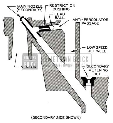
1952 Buick Carter 894-S Carburetor Modifcation
The primary side is similar.
1952 Buick Carburetor Anti-Percolating Passage
- Primary- 1/4”
- Secondary – 3/8″
- Install air horn assembly and replace code identification tag with new “894-SA” tag.
- Install the new 75-846 metering rods and adjust rods as required.
- Install carburetor assembly and check operation.
Production carburetors, to be introduced very shortly, will have an equivalent change and will be identified by the code number “894 -SA”.
BASIS FOR HANDLING ADJUSTMENT
We do not wish to have this modification handled on a “campaign• basis. Correction should be made only to settle complaints. We also wish to emphasize that the condition involves engine stall or hesitation on acceleration after the car is started with a warm engine. This is not a correction for the “idle freeze” condition that we have been experiencing for the past several years on 2-barrel carburetors.
The Carter Carburetor Corporation will make the previously mentioned service kit (Part No. 75-847U) available through all Authorized Carter “Sales and Service” Stations. Buick dealers have the option of making the modification in their own shops or having the service performed by one of these Carter “Sales and Service• Stations (see yellow pages in telephone directory). The following procedure must be followed in order to obtain credit:
Option No. 1
- Remove carburetor from car and deliver properly tagged to Authorized Carter Sales and Service Station.
- Upon completion of work, reinstall carburetor on car.
- Submit an AFA for “R & R carburetor”, .5 hrs., in the regular manner, accompanied by a copy of the Carter No-Charge Invoice.
Option No.2
- Purchase a Service Kit, Part No. 75-847U, from an Authorized Carter Sales and Service Station.
- Rework the carburetor as outlined previously.
- Submit an AFA, in the regular manner, showing “R & R carburetor”, .5 hrs., and “Rework carburetor”, .5 hrs., accompanied by the brass code identification tag “894-S” that was re- moved from the carburetor.
- Attach the Return Material Tag, Carter Form P-8787 (contained in kit), properly filled out to the metering rods that were removed from the carburetor and submit to the Authorized Carter Sales and Service Station from whom the service kit was purchased. This will serve as their authorization to reimburse you for the price of the kit
CARBURETOR FLOAT SETTING
1952 SERIES 70
Some confusion apparently exists in the field regarding the correct float setting for Series 70 four barrel carburetors. These specifications are as follows:
Carter – WCFB – 894S

1952 Buick Carter Carburetor Float Setting

1952 Buick Carter Carburetor Secondary Float Setting
Stromberg – 4AUV – 267
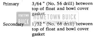
1952 Buick Stromberg Carburetor Float Setting
Note: Float setting on both carburetors is made with the bowl cover assembly inverted.
We have received a few reports that dealers are setting the Carter floats so that the fuel level is at the bottom threads in the sight hole. Due to specification changes after all tooling was completed the sight holes are incorrectly located and must not be used for gauging fuel level.
4-BARREL CARBURETOR REWORK
1952 SERIES 70
Supplements Sec. 3-A, Par. 3-1 (band c), 1952 SM Listed below are the steps necessary to modify Stromberg and Carter 4-barrel carburetors, in order to shorten the length of cranking time when starting a hot engine.
These changes are not to be campaigned; however, all complaint cars should be modified and, in areas where the condition is prevalent due to extreme hot weather, we feel that dealers should modify 1952 Roadmaster carburetors as these cars come in for other services.
AFA’s for this modification will be accepted on a time allowance basis of 1.7 hrs. for either make of carburetor. This time includes all the operations listed below. Only one serial number may be shown on each AFA.
As soon as possible, similar changes will be made in production and the carburetors will be identified by new code numbers as follows:

1952 Buick 4-Barrel Carburetor Codes Correction
Extreme care should be taken in all drilling operations and holes should be carefully located and prick-punched before drilling.
The lead balls called for in Step 8 of the Stromberg rework and Step 7 of the Carter operation should be approximately 1/8″ diameter. These may be obtainable through your local UMS Service Station or common lead buckshot of the correct size may be used.
Economy and general performance should not be affected by these modifications.
STROMBERG CARBURETOR
- Remove carburetor from the engine.
- Remove the air horn and float bowl cover assembly from the main body.
- Remove the float assemblies from the cover.
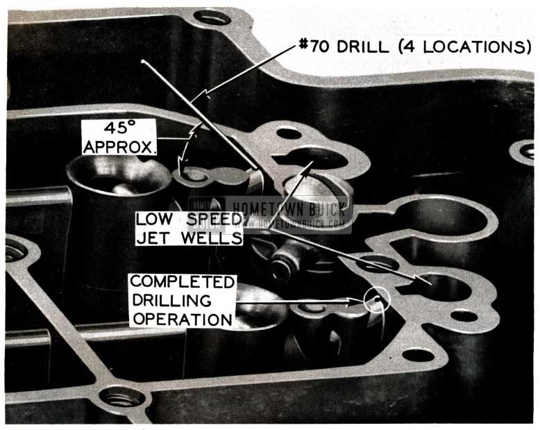
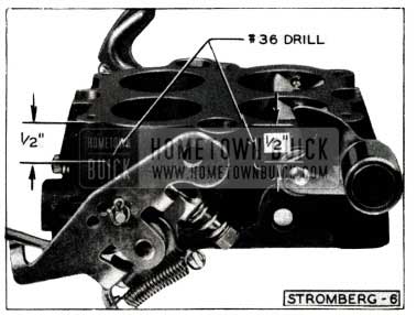
- Working from the bottom side of the cover, drill four (4) No. 22 (.157) holes through the air horn rim and cored passages as shown in Figures 11 and 12 .
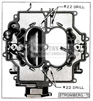
1952 Buick Stromberg Carburetor Bottom Side
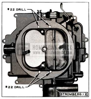
1952 Buick Stromberg Carburetor Air Horn
1952 Buick Stromberg Carburetor Vent Passage
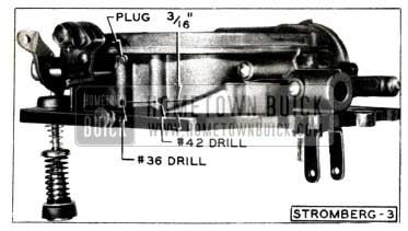
On the secondary side, drill a No. 42 (.0935) hole in the same manner.
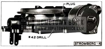
1952 Buick Stromberg Carburetor Plug
1952 Buick Stromberg Carburetor Vertical Passage
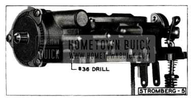
1952 Buick Stromberg Carburetor Throttle Body Holes
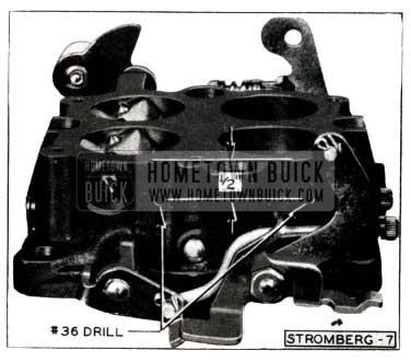
1952 Buick Stromberg Carburetor Throttle Body Drill Holes
CARTER CARBURETOR
- Remove carburetor from the engine.
- Remove the air horn from the main body.
- Remove the float and needle assemblies. Mark floats so they can be reassembled in original position.
- Remove the choke housing, and choke valves and shaft.
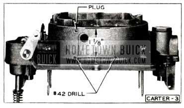
- Working from the bottom side of the air horn and cover assembly, drill two (2) 1/8″ (.125) holes through the cored passages on the secondary side (See Figure 18).
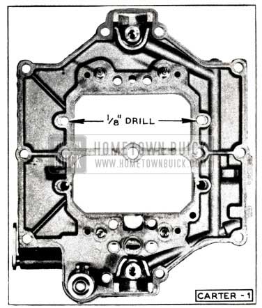
1952 Buick Carter Carburetor Cored Passages
1952 Buick Carter Carburetor Venting Operations
1952 Buick Carter Carburetor Air Horn Holes
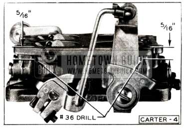
1952 Buick Carter Carburetor Throttle Body
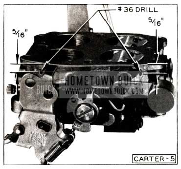
1952 Buick Carter Carburetor Throttle Body Holes
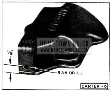
1952 Buick Carter Carburetor Metering Rod Housing Cover
NOTE: In the modification procedures for both carburetors, it is satisfactory to use 1/8″, 7/64″ and 3/32″ drills if the specified No. 22, No. 36 and No. 42 drills are not readily available.
CARTER 4-BARREL REWORK
1952 SERIES 70
We have received a few reports of erratic carburetor operation after performing the “hot start” modification on Carter 4-barrel carburetors. This condition has been traced to haphazard location of vents in the air horn assembly.
The locating dimensions given above are not intended as just a general guide-they must be strictly adhered to in order to insure satisfactory carburetor operation.
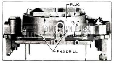
1952 Buick Carter Carburetor Air Horn Holes
For example, Figure 24 shows the venting operations in the choke side of the Carter air horn. This view locates the No. 42 vent, at the right side, in a position 13/16″ from the edge of the air cleaner positioning flange. A cutaway view of this area is shown in Figure 25.
1952 Buick Carter Carburetor Air Cleaner Positioning Flange
It can be readily seen that a 1/8″ error is locating the vent, together with a slight amount of porosity in the air horn casting, will result in venting the choke piston vacuum passage to the atmosphere. If this occurs, the piston is unable to actuate the choke valve, which will remain partially closed after the engine is completely warmed-up.
This is only one of the unsatisfactory conditions that may result when the modification instructions are not closely followed and it should serve to stress the importance of careful workmanship.
STROMBERG CAMPAIGN
1952 SERIES 70
We have encountered a condition with Stromberg 4-barrel carburetors in which the pin used to mount the fast idle cam and start aid lock lever may work out of the main body.
In order to avert any possibility of this condition occurring in owners’ cars, we are campaigning a simple modification and we are vitally interested in having all Stromberg 4-barrel carburetors modified with the least possible delay. One of the best means of insuring that the “fix” is made will be to check all 1952 Series 70 cars when they come in for service and perform the modification if the car is equipped with a Stromberg carburetor.
The following procedure should be used:
- Remove air cleaner and silencer assembly.
- Carefully center punch the main body projection (used as base for mounting fast idle cam and start aid lock lever) in a position along the front edge approximately 1/4″ above lower front corner (see position of drill in Figure 26).
1952 Buick Stromberg Carburetor Cotter Key
AFA’s will be accepted on a basis of .3 hrs. for this modification. More than one car may be shown on an AFA providing serial numbers of all jobs are listed.
Production carburetors have now been modified through use of a longer pin. On these jobs, the end of the pin slightly protrudes from the underside of the body casting projection and can be felt with the fingers. No change was made in the carburetor code number when this modification went into production.
FUEL PUMP SQUEAK
1952 ALL SERIES
In the majority of cases, fuel pump “squeak encountered with 1952 models is caused by the vacuum diaphragm spring rubbing against the sides of the spring recess in the pump cover. To assist in eliminating this condition, the Parts Department has released a new vacuum diaphragm spring, Group 3.901, Part No. 5590533. The new spring will be available through all Buick Parts Warehouses about September 1, 1952.
Replacement of the diaphragm spring can be satisfactorily made, without removing the pump from the engine, by using the following procedure:
- Remove vacuum lines from pump cover.
- Remove cap screws that attach vacuum cover to pump body.
- Lift off cover and remove diaphragm spring.
- Being careful not to unhook diaphragm pull-rod, clean cover and diaphragm with a cloth. NOTE: If diaphragm is cut, torn or folded, discontinue repair and replace pump.
- Use a file to clean up any ridges and grooves in the spring recess in cover.
- Loosen pump to crankcase mounting bolts 3 to 4 turns. This will move pump rocker arm away from cam and permit new spring to flex vacuum diaphragm as cover screws are tightened. Alternate Method: Disconnect coil high tension lead at distributor and turn engine with starter until diaphragm is at bottom of stroke.
- Place spring locator on center of diaphragm and place new spring, Group 3.901, Part No. 5590533, on locator.
- Position vacuum cover over spring and insert No. 10-32 x 1W’ screws through cover and diaphragm at two opposite locations. Take-up screws 2 or 3 turns into pump body threads.
- Press cover down and insert regular cover screws and lockwashers. Replace two long pilot screws with regular screws and lockwashers. Turn down all screws until heads make contact with washers.
- Inspect diaphragm for uniform setting around entire pump circumference. If diaphragm protrudes excessively at any point, it can be equalized by pulling on the diaphragm tabs as necessary.
- Tighten cover screws and pump mounting bolts (or install coil high tension lead).
- Install vacuum lines to cover.
- Test windshield wiper action with engine under load.
Leave A Comment
You must be logged in to post a comment.