WHEEL SHIELD EDGING
We have been advised by the Parts Department that the Rear Wheel Shield Edging, Group 8.177, Part No. 1336292, used on 1949 Series 50 and 70 after jobs is no longer serviced due to unavailability of steel used as an insert in the part. As a result, this part will be replaced by Group 8.177, Part No. 1331978, which is the edging used on 1949 Series 50 and 70 first jobs.
When it is necessary to install the 1331978edging on a car originally having the 2nd type edging, the following procedure should be followed:
- Remove the old edging and retainers from the fender and body.
- Procure 1st type edging retainer clips, Group 8.177, Part No. 1332045, as required. (Models 51, 59, 71, 79 require 22 clips. Models 56S, 56C, 76S, 76C, 76R require 20 clips.)
- Install the retainer clips, evenly spaced on the fender and body, with #8-15 x 1/2 round head, slotted, self-tapping screws. Make sure that clips are positioned correctly so that the edging will seal properly when the shield is installed.
- Insert a 45″ length of .090″ diameter wire through the hole in the edging.
- Install the edging in the retainer clips by crimping them in a manner that will securely retain the edging.
HOOD FASTENER RODS
The present hood fastener operating rods, Group 8.029, Part Numbers 1342489 (1950-40-50, 1951- 50) and 1342612 (1951-40) will be replaced by a new rod, Part No. 1344637, when present stocks are exhausted.
The new rod will have the same overall length as the 1342489 rod but will be threaded for a length of 3.54″ so that it can be used on both the 1950 and 1951 Series 40 and 50 jobs. When used on 1951 Series 40 cars, it will be necessary to cut off the 1 3/4″ excess length.
1951 RADIATOR GRILLES
Special Service Letter – Dealer #90, Feb. 8, 1951
SUBJECT: 1951 Radiator Grilles – First Jobs
A campaign change is being made on the radiator grille bar assemblies used on the first 1951 model cars, and it will be necessary to add reinforcements to all of the first type assemblies on cars which you have received.
Figure 52 shows a picture of the construction of the upper ends of the grille bars where they attach to the upper rail.
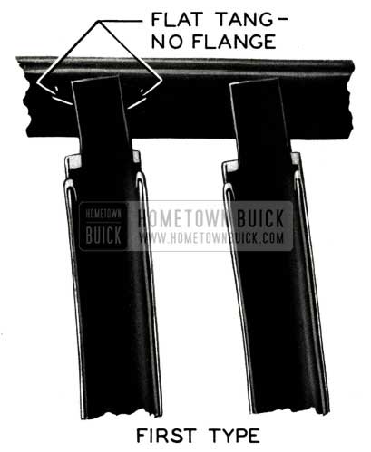
1951 Buick Radiator Grill Bars Upper Ends
This is the first type and must be reinforced. Figure 53 shows the construction as it is now in production, which is O.K. as it is.
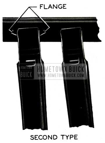
1951 Buick Radiator Grill Bars Upper Ends Flange
The reinforcements are stocked in all warehouses as “Reinforcement, bumper grille assy., upper”. A left and right are required for each job as follows:
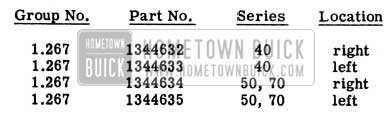
1951 Buick Radiator Grilles Parts
It is suggested you find out how many cars require campaigning and order the necessary parts at one time. The chances are that any cars shipped after January 26, 1951, will have the second type grille.
Following are instructions for removing the grille body and installing the reinforcements:
- Disconnect the 2 outer grille bars from parking lamp housing (short grille bar at each end).
- Remove grille hold-down bolts at bottom rail and at each end of top rail.
- Disconnect left parking lamp wires from junction block.
- Remove the left outer bumper guard and lamp assembly.
- Remove the 2 inner bumper guards.
- By careful manipulation, remove grille bar assembly as a unit between bumper face bar and radiator grille frame from the front.
- Cover work bench with suitable padding such as fender cover, to avoid scratching the chrome grille bar.
- Install reinforcements as shown in Figures 54 and 55.
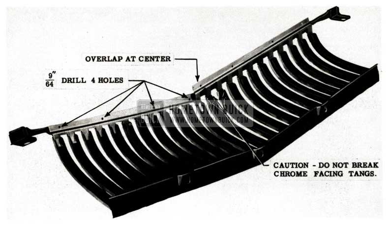
1951 Buick Radiator Grill Reinforcements
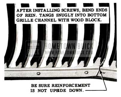
1951 Buick Radiator Grill Reinforcement
You will note that inside tangs of each reinforcement overlap in center grille bar. If spacing of bars is unequal, it may be necessary to trim one or two of the tangs. (CAUTION: If tangs are trimmed too much, so they don’t fit snugly in channel of grille bar, they will not do a good stiffening job on the bar.) A hammer and wood block will probably be required to drive the reinforcement into position. Care should be taken to avoid breaking the small flanges of the chrome pieces which hold them to the top end of the grille bars. Reinforcements can be incorrectly installed “upside down”, so be sure you do it as shown in Figure 55.
Flat rate allowance for this campaign is 1.3 hrs. When filling out AFA’s, please state “Campaign
#1 Grille Reinforcement”. More than one car may be listed on an AFA, providing serial number of each car is shown.
Leave A Comment
You must be logged in to post a comment.