SERIES 70
All 1952 Series 70 models make use of advanced insulating methods designed to reduce engine and road noise and contribute greater to passenger comfort (illustrated in Figure 48).
1952 Buick Body Insulation
Under hood insulation has been quadrupled so that nearly 100% of the hood surface is covered, and the thickness of the material has been increased from 3/4″ to 1 1/2″.
The insulating mat at the dash panel has been made 50% heavier to provide an improved sound barrier between the engine and passenger compartments. All other insulating features used on 1951 models have been retained.
EXTERIOR COLORS
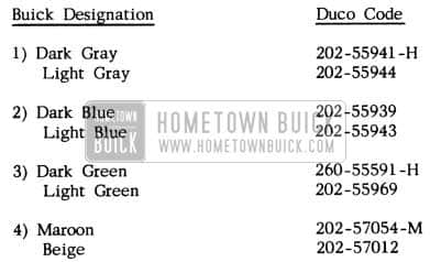
1952 Buick Exterior Colors
1952 Buick Paint Combinations
1952 Buick Paint Colors
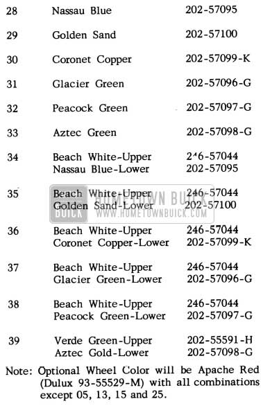
SERIES 70 SPECIAL COLORS
1952 Buick Roadmaster Series Paint Combinations
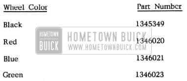
Note: Optional Wheel Color will be Apache Red (Dulux 93-55529-M) with all combinations except 05, 13, 15 and 25.
Service Use of Special Colors
The Series 70 Special Colors have a high percentage of aluminum pigment and, consequently, difficulty, will be encounted if small area spot repairs are attempted. We recommend that all service use of these colors be confined to panel repair.
In order to obtain the same color effect as produced originally in production, we suggest that the special colors be applied with a maximum film thickness per coat so that the desired thickness can be obtained in three to four coats, rather than in the usual six to eight coats.
The special colors should also be subjected to a minimum of compounding and polishing so that the possibility of scaling and mottling is reduced. In all other respects, these colors should be handled in the same manner as other Duco metallic lacquer finishes.
INTERIOR COLORS
A total of four interior color combinations are used in 1952 models, depending upon the trim option specified.
1952 Buick Interior Colors
Some of these interior colors are also used by other General Motors Divisions. For that reason, the color name as printed on the paint cans may not appear to be correct. Identification should be made by Duco Code Number only.
STEERING WHEEL COLORS
Steering wheel colors will harmonize with the interior trim color as follows:
1952 Buick Steering Wheel Colors
BODY WELD LINES
1951-52 SERIES 40: 1950-51-52 SERIES 50-70
In response to requests from the field we are publishing diagrams (Figures 49 thru 56) showing body weld lines for all 1951-1952 Series 40 and 1950-1951-1952 Series 50-70 cars. For information regarding interchangeability of Series 40 rear quarter outer panels, see page 12-6 of the 1951 Buick Shop Manual.
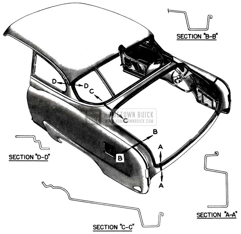
1952 Buick Body Weld Lines Diagram
1952 Buick Body Weld Lines Diagram – Model 45R
1952 Buick Body Weld Lines Diagram – Model 46C
1952 Buick Body Weld Lines Diagram – Models 46-46S
1952 Buick Body Weld Lines Diagram – Models 41-41D
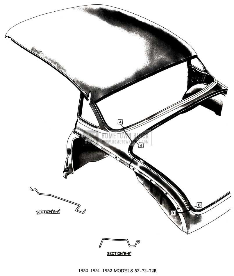
1952 Buick Body Weld Lines Diagram – Models 52-72-72R
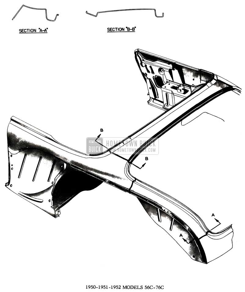
1952 Buick Body Weld Lines Diagram – Models 56C-76C
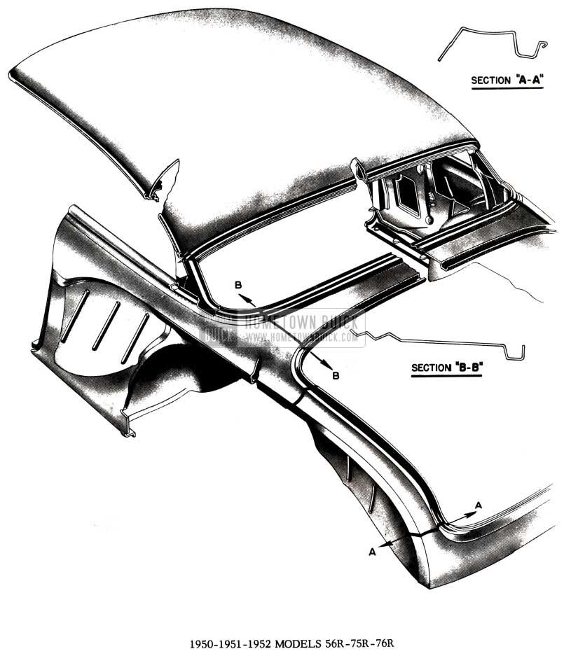
1952 Buick Body Weld Lines Diagram – Models 56R-75R-76R
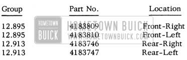
DIAGONAL AND DIMENSIONAL MEASUREMENTS OF THE SERIES
50 MODEL 52 BUICK BODY
There have been requests from the field for certain diagonal dimensions and measurements of Buick bodies to assist in analysing the extent of the damage on a wreck job and the subsequent repairs needed to rebuild it. Because it is the most popular style, Model 52, or 4-Door Buick Super, was used in making the following measurements. These measurements, therefore, will apply to all Model 52 cars from 1950 through 1953. Though some of these dimensions may not apply to the Series 40 and 70 Models, the reference points used to obtain these measurements in the following charts on the Model 52 may be found and used when working on the other series and models. It must be cautioned, however, that the measurements shown for the Model 52 are merely an average of many bodies measured and therefore, should not be used as a standard or final measurement but only as a general reference or starting point from which to begin repair operations. This is due to the manufacturing tolerances and unavoidable variations present in mass production. Therefore, measurements on seemingly alike parts may vary up to a plus or minus 1/8 inch or a possible total of 1/4 inch. Much of this dimensional variation in identical parts is due to the use of different dies in stamping out the sections. For this reason, in an attempt to achieve the greatest accuracy when using other jobs for measurement reference, right side dimensions should be made from a similar right side of an identical year, model, and series and left sides in the same manner. If another identical model is not readily available from which to take these measurements, then the opposite side of the wreck job should be used if possible.
If the reference points used in the following illustrations are not readily accessible or other points are more convenient, the latter should be used. A note of caution, however: where alternate reference points are used, care must be exercised in their choice. Press marks, die holes or major body bolts should be used for the bases or points of measurement as they are less likely to be effected by production variations.
In the final analysis, it is understood that the various sections of the body must fit into their proper place and that these measurements should be used only as an aid in arriving at this proper place or location without hindrance to the user.
Due to the obstructions found in taking the measurement in some of the following illustrations, most of these dimensions were made with the aid of a trammel bar. However, many of these measurements may easily be made with a standard steel tape. The points chosen are easily accessible without disassembly of trim or other body parts in undamaged areas. However, some of the diagonal measurements across the interior of the body require the removal of the front seat.
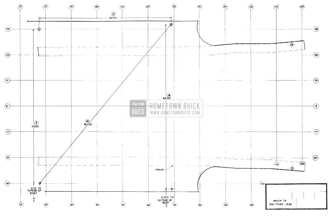
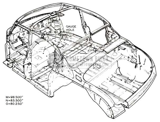
1952 Buick Floor Pan – Model 52
FIGURE 57 is the floor plan of a Model 52 Buick. All the measurements used in the following illustrations were taken from one of the four main gauge holes as shown in the floor plan. (Pictured gauge holes, Fig. 58, Views 3 and 4, page 175). It is from these four gauge holes that the whole body is constructed. These holes are used as a guide in the various jigs and fixtures as the body is assembled. The rubber fillers used to fill the gauge holes, after the body is completed in production, may be used for measurements by locating their center and measuring from that point. Therefore, maximum accuracy may be obtained if 3/4 inch bolts are placed in the gauge holes and the center of their heads used as the measuring point (allowing 1/4 inch for the thickness of the bolt head). All measurements in the following illustrations were made with the rubber fillers in the gauge holes.
The front gauge holes are readily accessible by lifting the edge of the rubber floor mat and rolling it inward (See Figure 58, View 3). The rear gauge holes are equally accessible by removing the retaining tack from the rear carpet and rolling the rug inward (See Figure 58, View 4).
1952 Buick Body Construction
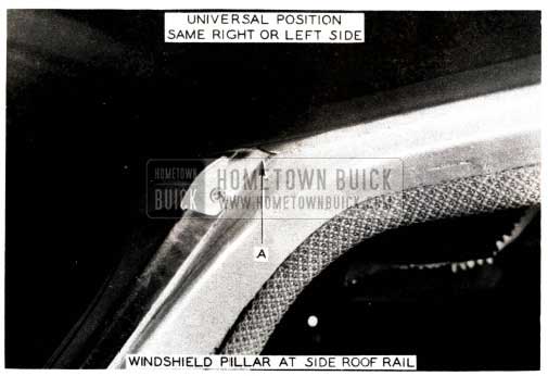
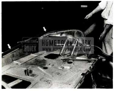
1952 Buick Windshield Pillar at Side Roof Rail
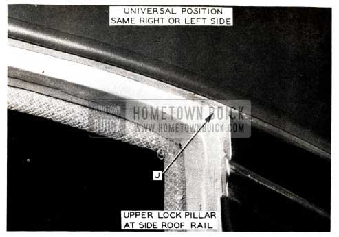
1952 Buick Upper Lock Pillar at Side Roof Rail
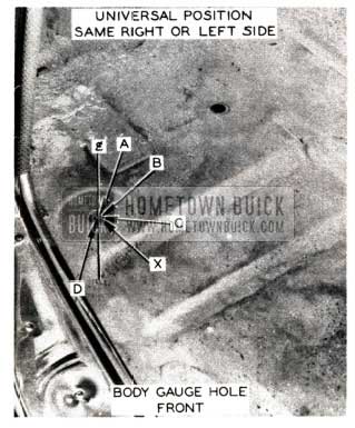
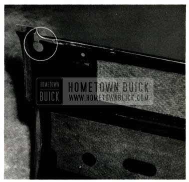
1952 Buick Body Gauge Hole Front
1952 Buick Body Gauge Hole Rear
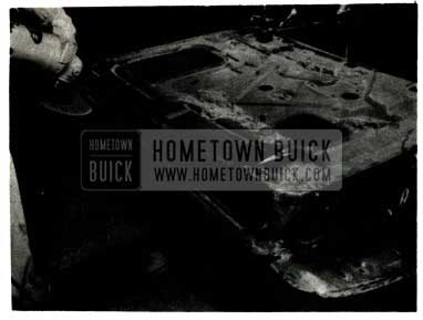
1952 Buick Weld Joint Rear of Rocker Panel
FIGURE 58, Page 174 is a side view of the Model 52 Buick. To help in showing the exact points used in the measurements, auxiliary views, in pictures, are supplied on Page 175 directly below the side view drawing. The more readily identified measuring points are described next to their reference points on the drawing itself. (See Line C in Figure 58).The arrows in the auxiliary pictures correspond with the arrows in the drawing itself. Therefore, Line A in Figure 58 is shown in the picture Figure 58, View 1 on Page 175 and points to the exact point the measurement should be made to, from the front gauge hole.
1952 Buick Body Measurements
FIGURE 59 as shown in the drawing is sectioned at 16. These sections mean that this view was taken at a point 16inches back from the zero (front of dash) line. To illustrate, in the side view drawing, (Figure 58) the body is sectioned off in perpendicular lines. Upon inspecting the side view it is seen that these sections are in units of 10 inches. Therefore, counting from the front or left side of the drawing (Figure 58) note where the 16 line falls. It is at this point that Figure 59 was drawn. This holds true for Figure 60 (sectioned at 69) and Figure 61 (sectioned at I 20). This same sectioning plan pertains totheviewsofFigures59, 60 and61. Therefore, the centerline is drawn directly down the center of the body. Progressing out to either side from this center line, the body is sectioned off in units of 10 inches.
1952 Buick Body Dimensions
FIGURE 60 is sectioned at 69 and shows the body as it appears at the rear gauge holes looking toward the rear of the body.
1952 Buick Rear Body Dimensions
FIGURE 61 is sectioned at 120 as shown in the drawing. It is taken at the 120 inch line, in the trunk, looking toward the front of the car.
1952 Buick Trunk Striker Latch
FIGURE 62 Page 179, is a view of the rear compartment lid lock striker latch. As illustrated in Figure 62, scribe lines are drawn from the two rear body bolts in the trunk to the lower inside bead-edge of the rear end panel (See Figure 63, Line L). In making this measurement, it is necessary to remove the spare tire from the trunk. Using the two trunk body bolts as a base point, scribe an “X”, as shown in Figure 62on the inside edge of the rear end panel. Where the two scribe lines cross will be the center of the rear end panel. This point should measure 33 7/8 inches from either of the two trunk body bolts used as a base in the measuring. In rebuilding a wrecked trunk area, cut two pieces of string and tie them to the two body trunk bolts. Measure and mark each piece of string at 33 7/8 inches from the trunk body bolts (center of bolts). Where the two marks come together will be the center, and proper position of the rear end panel (if frame is not damaged or out of line).
1952 Buick Body Gauge Holes
FIGURE 63, Page 179, is a phantom or isometric view of the Model 52 body. This view shows how the various dimensions shown in the previous illustrations, appear on a true view figure. As previously stated, the measurements, though only shown on one side of the body, pertain to the other side.
1952 Buick Body – Front View
FIGURE 64 further illustrates the various measurements shown in FIGURES 58, 59, and 60.
1952 Buick Body – Rear View
FIGURE 65 is an isometric illustration but Lines M, N, and 0 shown are not on any of the previous illustrations. This view was used due to the difficulty in properly showing these lines on the standard type drawings of Figures 57, 58, 59, 60 and 61. These diagonals are drawn across the inside of the car and from front to rear.
As stated, all measurements illustrated in the figures are not meant to be final or the “only” measurements possible within the body. These measurements are only meant as a guide in rebuilding wreck jobs or as a basis for setting up more complete and comprehensive measurements which may be required.
RELOCATING FRONT SEAT
1951 – 1952 ALL SERIES
Occasionally we receive owner letters regarding the advisability of relocating the front seat mounts in order to provide more driver leg room. We are not in favor of this modification because the heater guard assembly projects beyond the front of the seat cushion, the front floor mat is not long enough to cover the additional floor area, and the seat installation is structurally weakened because all of the relocated mounts do not fall in reinforced floor pan areas. We realize, however, that some owners will demand this modification and, in such cases, they should be fully informed of the above factors and it should be clearly agreed that the owner will accept full responsibility for any unsatisfactory conditions that may result.
The maximum suggested distance for moving the seat mounts toward the rear is 1″ on Series 40 jobs and 1 1/2” on Series 50-70 cars. The following procedure may be used:
- Remove front seat assembly and scribe new mounting holes on floor pan, at distances suggested above.
- Series 40 – Drill front mounting holes 11/32″. Drill rear holes with “F” drill and thread with 5/16″-18 tap. Series 50-70 – Drill front, and outside rear holes 11/32″. Drill inside rear holes 3/16″.
- Cement 3/32″ windshield washer hose, split lengthwise, over all exposed edges on the front side of the heater guard and air outlet assembly. NOTE: This is extremely important.
- Series 40 – Install front brackets using 5/16″-18 x 1″ bolts and nuts with plain washer under head and plain and lock washer under nut. Install rear mounts with 5/16″-18 x 1/2″ bolts and plain washer under head in holes threaded in Step No. 2. Series 50-70 – Install mounts with 5/16″-18 x 1″ bolts and nuts in front, and outside rear locations. Use plain washer under head and plain and lock washer under nut. Use 1/4″- 20 x 3/4″ self-tapping screws with plain washer under head at inside rear locations.
CAUTION: No attempt should be made to relocate the front seat on models equipped with Hydro-Lectric controls.
76R FRONT SEAT BACK
1952 MODEL 76R
We occasionally receive reports indicating that the top outer comers of the front .seat backs on 1952 Model 76R rub against the door and rear quarter finishing panel mouldings and trim. If this condition is encountered it can be corrected as follows:
- Remove the front seat back.
- Bend the inner pivot arm slightly outboard as shown in Figure 66.
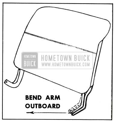
1952 Buick Front Seat Back – Model 76R
This will slant the top of the seat back away from the door and rear quarter.
SEAT CUSHION TRIM DAMAGE
1952 SERIES 40 TWO-DOORS
A few reports have been received concerning front seat cushion trim damage, caused by rough edges on the seat back hinge arms, on 1952 Series 40 two-door styles.
If this condition is encountered, the hinge arms should be reworked as follows:
- Remove the front seat side trim panel and remove the front seat back.
- Cut off flange “C” of the inner hinge arm as shown in View “X Figure 67 to obtain approximately 3/8” clearance between the flange and the seat cushion when the seat back is in the rear position.
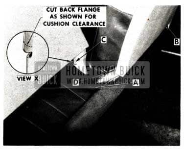
1952 Buick Seat Cushion Trim Damage Repair
The outer hinge arm also has a flange at location “B” that may be reworked the same way.
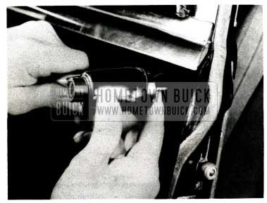
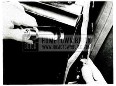
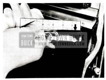
SEAT ADJUSTER KNOB
1952 ALL SERIES
In the near future all 1952 models will use a new type front seat adjuster knob which employs a spring retainer clip instead of the present set screw.
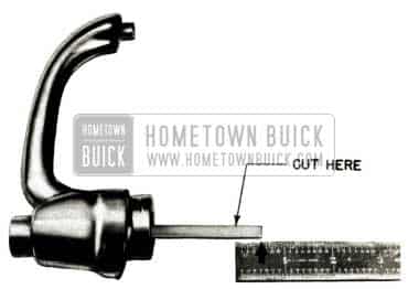
A suitable tool for removing the new knob can easily be made-up from a screwdriver with a 1/4” diameter shank, as shown in Figure 68.
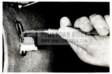
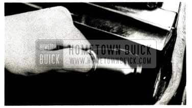
1952 Buick Seat Adjuster Knob
The knob is removed by depressing the spring clip by hooking the tool behind the knob as shown in Figure 3, and pulling the tool straight out from Figure 69.
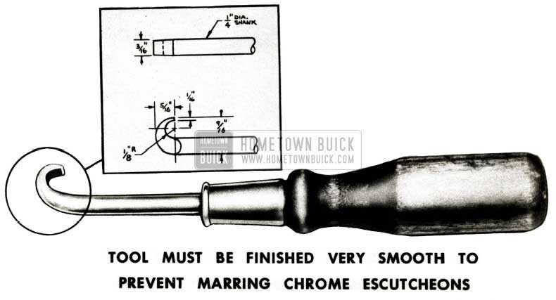
1952 Buick Seat Adjuster Knob Tool
The knob is replaced by merely snapping it on the locking lever arm by hand.
SCALP MOULDING REWORK
1952 MODEL 72R
During 1952 production, there will be two methods used for installing the vertical reveal moldings located at the front door lock pillar, center pillar and rear door hinge and lock pillars on the 1952 Model 72R.
On first production bodies of the above style, the door reveal moldings are attached by tab> which are bent around the hemming flange of the door. In some cases, this type installation results in a rough edge of the molding at the door hemming flange particularly at the door lock pillars. Rough edges have also been found on the center pillar scalp molding.
In the event this condition is encountered, the reveal moldings can be reworked according to the following procedure.
- Using emery cloth, smooth off the rough edge of the front and rear door reveal moldings at the door hemming flange. View A in Figure70 shows the location of the rough edge at the front door lock pillar.
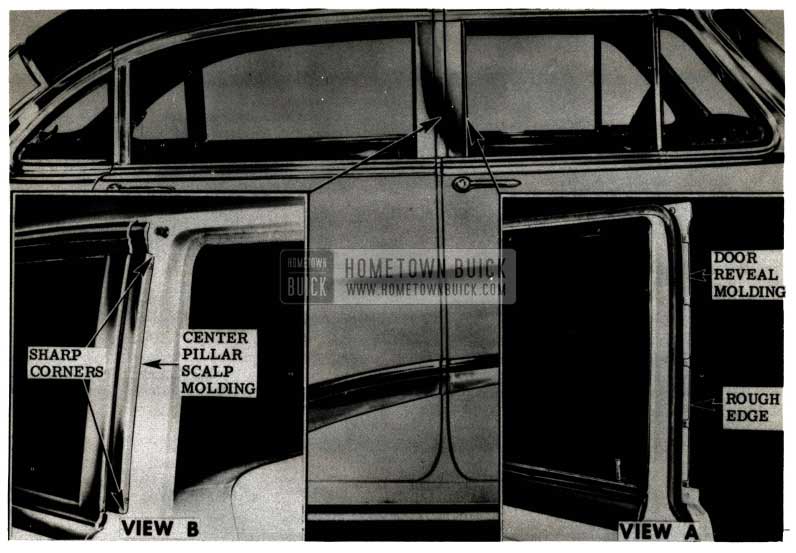
1952 Buick Scalp Moulding Rework
After smoothing operations, brush touch-up the paint surfaces as required.
Before replacing the scalp molding on the center pillar, bend the side of the molding inward so that the edges of the molding fit up tightly against the center pillar, then reinstall the scalp molding.
Later production bodies will contain moldings installed with sheet metal screws, located under the upper and lower reveal moldings, which will eliminate this problem.
REAR DOOR LOCK BIND
1951-1952 MODELS 41-410
We have uncovered a few 1951 and 1952 Series 40 jobs where the rear door lock tie-bar binds on the intermittent lever when the lock is set for free-wheeling operation. This condition makes it impossible to open the door from the inside, regardless of whether the inside locking rod is in the “up” or “down” position.
If this condition is encountered, the lock should be reworked as follows:
- Remove lock assembly.
- Bend square corner of tie-bar toward center of body as shown in View “A”, Figure 71.
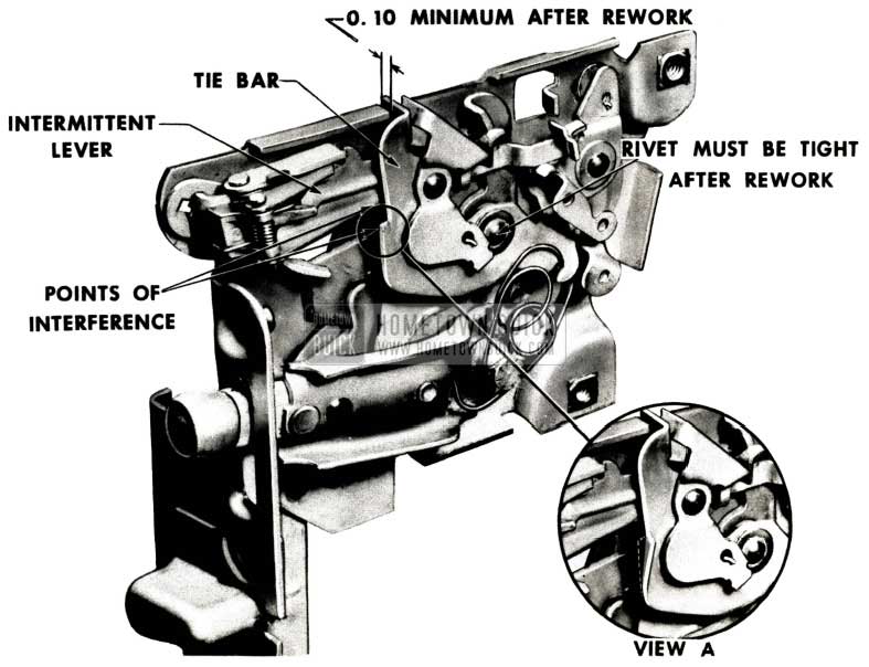
1952 Buick Rear Door Lock Bind
Pliers can be used for this operation. CAUTION: Restrict bending to sharp corner only and be careful not to loosen the rivet holding the tiebar and free-wheeling trip sub-assembly to the frame. A minimum dimension of .100” must be held at the contact point between the tiebar tab and lock frame flange after rework (Figure 71).
PUSH-BUTTON LOCK SHAFT
1950-51-52 ALL SERIES
During 1952 production, improvements will be made in door locks to decrease push- button effort. This design change makes it necessary for the pushbutton to have a certain amount of “free-travel” before the push-button shaft contacts the lock mechanism.
If the push-button shaft is not the correct length, the door lock will not operate properly, and the following procedure should be followed when fitting a new shaft or refitting the old shaft where possible:
- Install shaft and cylinder assembly in the door handle and insert the handle in door, carefully guiding the shaft into the lock (See Figure 72).
1952 Buick Install Shaft and Cylinder Assembly in Door Handle
1952 Buick Raise Lift Bolt
1952 Buick Push-Button Door Handle
If the bolt snaps down, the shaft is in the correct position.
1952 Buick Push-Button Door Handle Measurements
When taking this measurement be sure the handle is held at the same relative angle with the door as when the handle is fully installed.
1952 Buick Door Handle Shaft
Remove the handle from the door and cut off end of shaft the distance measured in Step No. 3 plus an additional 1/32″. (The 1/32″ will permit “free -travel” of the push-button before the shaft contacts the lock mechanism). After cutting, remove all burrs from the shaft.
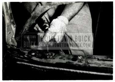
FRONT DOOR OUTER PANEL
1950-1952 MODELS 52, 72, 72R
Damage that occurs in the forward end of front door assemblies used on recent models represents an extremely difficult repair job. This is due, of course, to the close relationship of inner and outer panels which provides adequate opening clearance at the cow1 side lower panel and front body hinge pillar. The difficulty of using required bumping tools at this point causes many body men to scrap the door rather than attempt satisfactory repairs. The ideal solution is to install a new door outer panel which will not only permit salvage of the door; but, will result in a considerable saving to the owner.
Front and rear door outer panels for “19” style sedans are now available through the Parts Department. These replacement panels are identical to original production units and simplify the installation problem as well as insuring that the repaired doors will meet original standards. The available panels can be used on all 1950 through 1952 Models 52, 72 and 72R as follows:
1952 Buick Front Door Outer Handle Parts
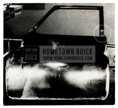
The 1950 Model 52 front door used for illustration purposes in this article was salvaged from the scrap pile after an unsuccessful attempt was made to repair extensive damage in the forward section. The following procedure for outer panel installation contains many operations that can also be applied to rear door panel replacement. Slight variations in rear door procedure will be readily apparent to experienced body repair men.
1952 Buick Salvaged Door
FIGURE 77 – This view shows the door exactly as salvaged. Note the impact in the forward section which has resulted in a sharp crease along the top of the front fender extension line (see arrow). The outer panel was partially repaired, prior to being discarded after clumsy repair efforts resulted in burning away a section of the front lower corner (circled in view).
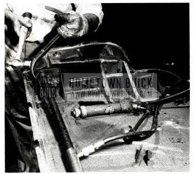
1952 Buick Door Underside
FIGURE 78 – View of the underside of door at the lower front corner. Note buckled condition in the lower hinge area (circled in view) and torn metal at the extreme forward edge.
1952 Buick Damaged Window Frame
FIGURE 79 – In this particular case the window frame is undamaged and it is necessary to replace only the lower part of the panel. A short portion of the window frame should be used, however, to avoid welding operations below the window line. The view shows a cut line being scribed across the lower end of the die located depression in the forward area of the window frame. This point is used because it will insure accurate fitting of the new panel. The outer panel is then hacksawed at the scribed line.
1952 Buick Window Frame
FIGURE 80 – The rear end of window frame is scribed and sawed, using offset along rear edge of door as a locating point. In event of damage in this area, higher point may be necessary. View shows chisel used to cut corner of inner window flange reinforcement.
1952 Buick Outer Panel Repair
FIGURE 81 – Sanding disc is being used to separate the outer panel from the flange.
1952 Buick Weld Operation
FIGURE 82 – An air chisel (or hand chisel) is used to break the spot welds which are used in production to position the outer panel prior to the multiple weld operations.
1952 Buick Forward Flange Repair
FIGURE 83 – The forward flange is broken with an air chisel. This can also be done with a hand chisel.
1952 Buick Broken Outer Panel
FIGURE 84 – The outer panel is broken loose at the vent opening with an air chisel (or hand chisel).
1952 Buick Removed Outer Panel
FIGURE 85 – Outer panel is now completely removed and the lower hinge area of the door is being restored to correct shape. A jack is used at the hinge reinforcement with the lower end (not in picture) bearing against a length of 1″ x 2″ block. The side of the hinge reinforcement is being straightened to approximate shape and location at the same time. Necessary welding should then be completed.
1952 Buick Hinge Reinforcement
FIGURE 86 – Position of the hinge reinforcement is checked by using a scale in the position shown. Note that left end of scale is seated against the door inner panel. A position higher up on the rear flange should not be used because edge of flange may not be in correct alignment. This dimension, on model 52 and 72R front doors, is 36 1/4″. View of scale shows 34 1/4″ plus 2″ allowance for scale case.
1952 Buick Window Frame Alignment Check
FIGURE 87 – Alignment of window frame with glass run channel is being checked with a straightedge. One end of bar is lined-up with channel lower mounting hole (see arrow) in a position 1/8″ away from flange. This compensates for the offset bracket used for mounting the lower end of the channel. The window frame must be parallel with straightedge or window bind will result. This check will also reveal any forward or aft shift of the window frame.
1952 Buick Front Fender Contour
FIGURE 88 – Front fender is being held in position to check contour of forward edge of door. Note that straightedge (see arrows) is used to project correct relationship of fender skirt to door. In this case, further straightening is required to improve door-to-fender fit at lower section.
1952 Buick Clean Inner Panel Flange
FIGURE 89 – Disc sander is being used to clean flange of inner panel. This will insure a good surface for brazing, arc welding or spot welding.
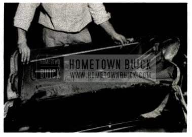
1952 Buick Outer Panel Replacement
FIGURE 90 – Replacement outer panel has been trimmed by using the same locating methods employed in removing old panel (Figure 79). Note that comer of inner reinforcement (circled in view) is cut to match section remaining on door (Figure 80). This is the only portion of the inner door frame used from the new panel. The Metal-Wrap protective coating was removed from both sides of panel flanges with a wire brush, to provide proper welding surface. The coating should be left intact on outer surface of panel to avoid handling bare metal.
1952 Buick Door Panel Replacement
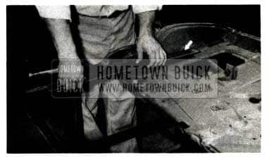
FIGURE 91 – The replacement panel is correctly positioned on door and flanges at upper ends (see arrows) are turned under to maintain position for welding. Gas butt joints are made on panel facing to join lower and upper sections. If door was twisted out of alignment by collision it should be checked at this point by hanging in door opening on body. The door frame should be twisted into alignment and held by tack welding the lower comers of the replacement panel. This alignment check must be made if front or rear bottom comers of outer panel are not in correct alignment with the inner panel after first welds are made.
1952 Buick Insert Center Punch
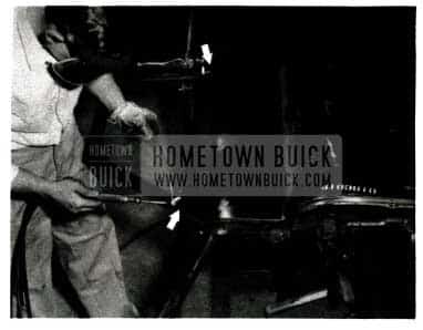
FIGURE 92 – Center punch (see arrow) is inserted through die holes in forward edge of panels to maintain alignment. Clamps are used adjacent to front fender extension line. View shows front flange being spot welded, using 220 volt, 30 amp. spot welder, but; gas welds may be satisfactorily used in this location.
1952 Buick Turn Flange under Door
FIGURE 93 – A dinging hammer and dolly are used to tum flange under along rear and bottom edges of door. Excessive hammering must be avoided after flange is turned because edges may stretch and make door too large for opening. Heat may be used around inside comers if necessary to shrink flange into place.
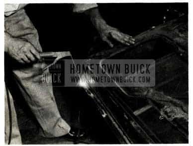
1952 Buick Outer Panel join with Panel Flange
FIGURE 94 – Outer panel is being joined to inner panel flange with arc weld, using 1/16″ arc rod and a 110 volt, low amperage welder. Gas welds may be used, but; heat distortion may occur, requiring extra metal finishing labor.
1952 Buick Metal-Wrap Protective Coating Removal
FIGURE 95 – Door is now ready for removal of metal-wrap protective coating and necessary metal finishing prior to painting. Note that butt joint in rear end of window frame (circled in view) has been solder filled. This is not necessary in forward end because joint will be covered by chrome trim.
1952 Buick Door Refinishing
FIGURE 96 – Door, ready for refinishing, is hung in door opening. The following points should be observed in completing this operation:
- Bottom edge of door should be sealed from the inside, with sealing gun, to prevent moisture that enters at window opening from entering joint and causing rust.
- When reinstalling weatherstrips on door, the cement should be applied so that it seals all flange joints.
CHECK LINK NOISE
1951-1952 SERIES 50-70
The following procedure for correcting door hold open check link noise on 1951 and 1952 Series 50 and 70 models supersedes similar instructions.
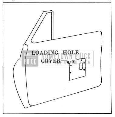
- Remove door inner panel hardware, trim pad and the door loading hole cover plate nearest the door check link.
- Remove the door check link by removing two (2) screws at the door inner panel and four (4) screws at the front body hinge pillar. Place the check link in a vise.
- Operate the check link and observe the action of the spring coils to determine where copper shims are required between the coils to prevent them from contacting each other. NOTE: Shims can be made from copper shim stock approximately 0.015 thick.
- If space is necessary to install the copper shims between the coils of the spring, the spring may be uncoiled. Using pliers, grip the end of the spring, shown at “A” in Figure 97, then apply pressure against the spring and carefully lift the end over the spring stop, shown at “B”.
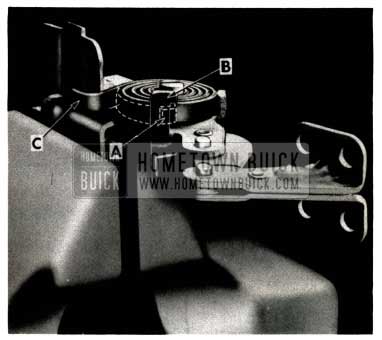
1952 Buick Check Link Copper Shims
Allow the spring to uncoil slowly until the end of the spring rests against the check link assembly at “C”. NOTE: Extreme caution should be used in releasing or reinstalling the coil springs in Steps 4 and 6, as they are under a stress load sufficient to cause them to fly and cause personal injury.
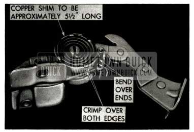
1952 Buick Copper Shim
This crimping operation improves the retention of the copper shim.
CHECK LINK SUPPORT
1950-1952 ALL SERIES
A simplified method has been developed for removing the rear door check link support on all 1950 through 1952 sedan styles. The new procedure, which results in a considerable time saving because it is not necessary to remove the door trim pad and loading hole cover, is as follows:
- Loosen center pillar trim.
- Remove the check link strap attaching bolt and remove the check link strap.
- Remove the two check link support attaching screws at “A” (Figure 99).
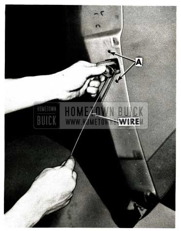
1952 Buick Check Link Support
NOTE: Insert a hooked wire around the support roller, as shown in Figure 99, to prevent the check link support from falling into the door while the screws are being removed.
- Remove the check link support by turning it and bringing it out the door cut-out as shown.
- Obtain a new check link support and install it to the door by reversing the above procedure.
WINDOW REGULATOR HANDLE
1952 MODEL 41D
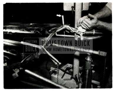
ln some cases, the front door window regulator handle, on the 1952 Model 410, contacts the trim molding on the door trim pad just below the handle . This interference can be eliminated by turning the handle to the area of interference and pulling toward the center of the body, as shown in Fig. 100, until sufficient clearance with the trim molding is obtained.
1952 Buick Window Regulator Handle
This rework changes the contour of the door inner panel at the window regulator attaching area.
DOOR WINDOW STOP
1952 MODELS 45C-45R
It has been discovered that the door loading hole covers shown in Fig. 101, were reversed in assembly on some early production Series 40 Convertible and Riviera Coupes.
1952 Buick Door Window Stop
That is, some of the right door loading hole covers were put on the left doors and vice-versa. This reversed condition causes the door window stop to be further inboard than the design calls for, and consequently the window does not contact the window stop. If this condition is found, the following procedure may be used to rework the door window stop so it will function correctly.
- Remove the door trim pad.
- Remove loading hole cover.
- Drill out four (4) welds holding window stop to loading hole cover.
- Insert two (2) hardwood shims and bolt the window stop to the loading hole cover (FIG. 102).
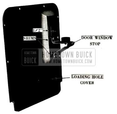
1952 Buick Door Window Stop Cover
NOTE: Paint shims before installation.
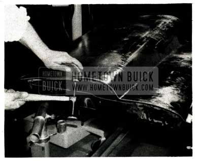
DOOR WINDOW “BIND”
1952 SERIES 50-70
We have encountered a few cases on 1952 Series SO and 70 jobs where the door window glass lower sash channel weatherstrip binds against the door outer panel flange reinforcement (See Fig. 103).
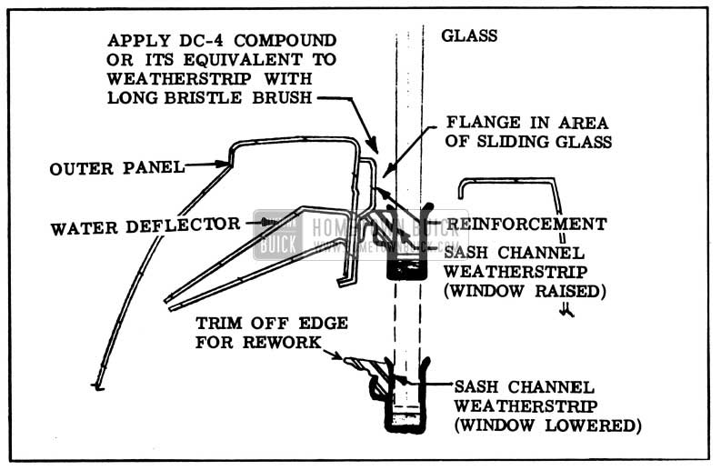
1952 Buick Slow Operating Windows Repair
This condition requires considerable effort when lowering the window from the full “up” position.
The following procedure should be used in handling complaints of this nature:
- Lubricate the weatherstrip with a suitable rubber lubricant, such as OC-4 compound or its equivalent, using a brush at the location shown on Figure 103.
- Check operation of window to determine whether the lubricant has eliminated the bind.
- If the lubricant has not eliminated the binding condition, the following additional steps should be taken.
- Remove door trim pad.
- Remove access hole cover.
- Take out window glass.
- Trim off edge of weatherstip as shown in Figure 103.
- Re-apply lubricant and reinstall glass.
- Check for correct operation of the window.
- Assemble the trim pad and hardware.
SLOW OPERATING WINDOWS
1952 MODEL 46C
Slow operating door windows on the 1952 Model 46C Convertible frequently result from a “kinked rubber hydraulic hose line in the front body hinge pillar. This condition can be corrected by rotating the forward end of the tubing outward as described below. When performing this operation, it is also advisable to determine whether the hose is “chafing” on the flange of the cowl side inner panel access hole. The correction for this second condition was outlined above, and is incorporated in the following procedure:
- Remove cowl side kick pad and insulation.
- Grip the forward end of the door window hydraulic tube with a suitable tool and carefully rotate the tube outboard, as shown in Figure No. 104.
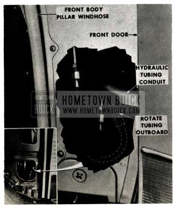
1952 Buick Front Body Pillar Windhose
1952 Buick Window Shroud Side Inner panel
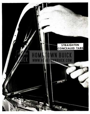
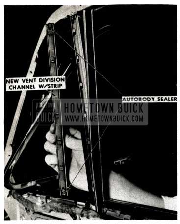
VENT CHANNEL WEATHERSTRIP
VARIOUS MODELS 1941-1952
We have had a number of field requests for a simplified method of replacing front and rear ventilator division channel weatherstrips. As a result, necessary parts have been released and a method of replacement, without removing the division channel assembly from the door has been developed. We wish to caution, however, that successful use of the following procedure requires very careful workmanship.
- Lower the door window and open the ventilator.
- On closed bodies, remove the door garnish molding and the upper section of the glass run channel along the door header.
- Straighten the two upper tabs “A” shown in Figure 106.
1952 Buick Vent Channel Weatherstrip
1952 Buick Vent Glass Run Channel
1952 Buick Vent Division Channel Weatherstrip
Install the weatherstrip to the division channel and clinch over all of the tabs except the two upper tabs.
NOTE: When clinching the tabs, the weatherstrip should be held firmly against the division channel to ensure a tight clinch.
- Place the glass run channel back in position on the division channel and clinch over the two upper tabs. It is very necessary that these tabs be clinched so they are below the surface of the pile in the glass run channel, otherwise the edge of the glass will contact the tabs when the glass is raised and glass breakage may result.
NOTE: On Convertible and Riviera coupe styles, make sure the door window glass bumper is in position at the top of the division bar before the glass run channel is placed back against the division channel.
- Install the glass run channel along the door header.
- Install the door garnish molding.
Ventilator division channel weatherstrips have been released for the following models:
1952 Buick Vent Division Channel Weatherstrip Models
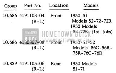
1952 Buick Vent Division Channel Weatherstrip for Models
FLIPPER SEAL SLEEVE
1952 MODELS 56R-76R
A nylon sleeve is now being used on the Model 56R and 76R Riviera Coupe side roof rail weatherstrip (flipper) to prevent the trigger from marring the chrome on the upper door vent frame. This sleeve is also available as a service item under Group 10.721, Part No. 4614586, and can be easily installed on first jobs. As shown in Fig. 109, the sleeve slips over the trigger and is held in place by the trigger lugs.
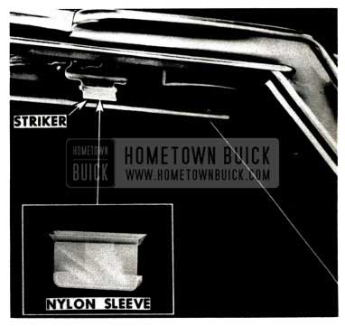
1952 Buick Flipper Seal Sleeve
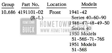
VENT DIVISION CHANNEL
1952 MODEL 41D
The Rear Door Ventilator Division Channels (Group 10.829) which will be released for 1952 Model 41D after jobs, differ from the channels used in first production jobs. The new division channel has the ventilator weatherstrip rubber retainer channel riveted in place instead of being attached with screws. In addition, it does not include the outer scalp, inner deflector, ventilator weatherstrips or upper glass run channel. These parts must be ordered separately and installed if necessary.
When installing the new type division channel it will be necessary to install the ventilator glass channel in the rubber retainer channel before installing the glass in the glass channel. This is necessary because the glass channel must be sprung slightly inward in order to engage the lower “T” shaft and upper pivot in the rubber retainer channel. This, of course, is not possible if the glass is previously installed.
FRONT DOOR VENT PIVOT
1951-1952 SERIES 40
In the event that the front door vent glass channel pivots, on 1951-1952 Series 40 (except45R-46C) cars, become damaged or corroded, they can be replaced as follows:
- Carefully remove the ventilator glass from the glass channel.
- Remove the ventilator assembly from the door.
- Drill out the pivot rivet “A”, Fig. 110, by drilling into the “peened” end of the rivet.
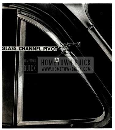
1952 Buick Front Door Vent Pivot
The following parts are used in the above operation:
1952 Buick Front Door Vent Pivot Parts
HYDRO-LECTRIC POWER UNIT
1952 HYDRO-LECTRIC STYLES
The latest type Hydro-Lectric motor and pump assembly used on 1952 models is a “low-speed'” upright type motor with an internal and external rotor type pump. This unit is designed for quieter and smoother operation than the assemblies formerly used. A 6 volt D.C. motor is mounted in a vertical position on the dash and the pump, which is attached to the underside of the motor, will deliver a maximum pressure of between 250 P.S.I. and 260 P.S.I. The pressure relief valve is the ball and sleeve type same as used in 1951 Hydro-Lectric styles. Component parts of the pump assembly are shown in Figure 111.
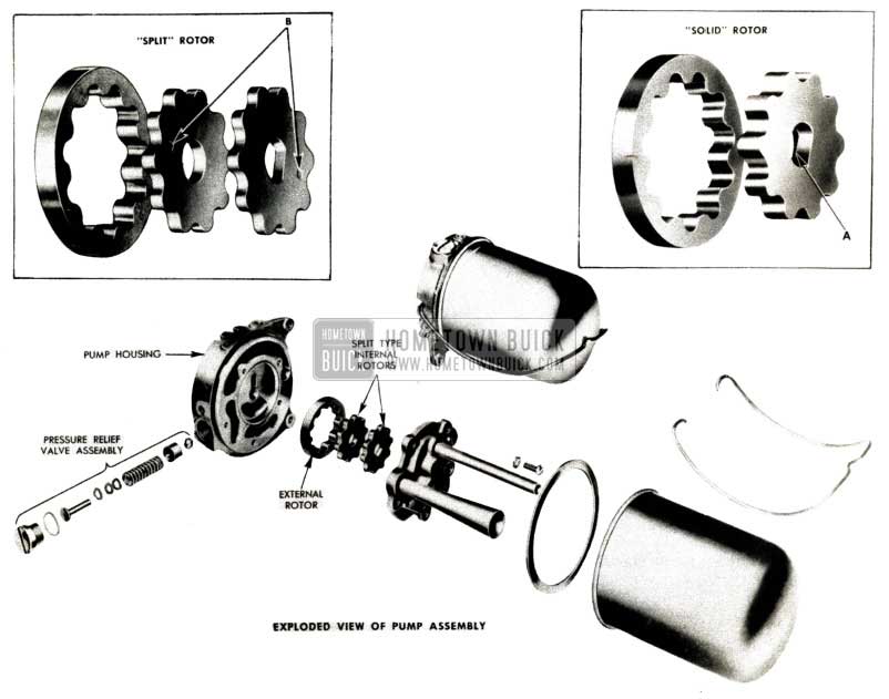
1952 Buick Hydro-Lectric Power Unit Assembly
The pump illustrated has a “split internal rotor• which is described below.
The first low -speed motor and pump assemblies used in 1952 production incorporated a 10 lobe “solid” internal rotor and 11 lobe external rotor as shown. The flat portion of the shaft hole is recessed out on one side of the rotor, see item “A”. When installing the rotor, the recessed side should be placed against the pump housing.
After a short period of time, the low -speed motor and pump was changed by installing “split” internal rotors, in place of the solid rotor. All other parts of the unit remain the same. This assembly can be identified by a daub of blue paint on the motor end plate.
When the “split” rotor pump is assembled in service, special care must be exercised to assemble it properly, as follows:
- Install the 11 lobe external rotor to the pump housing.
- Install the internal rotor with the circular shaft hole to the motor shaft. The rotor must be installed with the square identification mark on the side away from the pump housing.
- Install the remaining internal rotor to the shaft. (This rotor is slightly thinner than the one with the circular shaft hole.) Make sure the square mark is on the side away from the pump housing and 180 degrees (on the opposite side of the shaft) from the mark on the internal rotor installed in Step 2. Correct position of marks is shown by ‘”B” in Figure 111.
- Install the remaining parts of the pump in the usual manner.
HYDRAULIC LIFT RATTLES
1951 HYDRAULIC STYLES
In some late production 1951 models with hydraulic window lifts, rattles are encountered in the window lift assemblies.
Outlined below are four frequent causes of this condition, with the proper correction for each:
- The Spring Clip “A” (See Figure 112) is bent or broken as the result of pressure exerted on it by the arm “B” when the window is in the full “up” position.
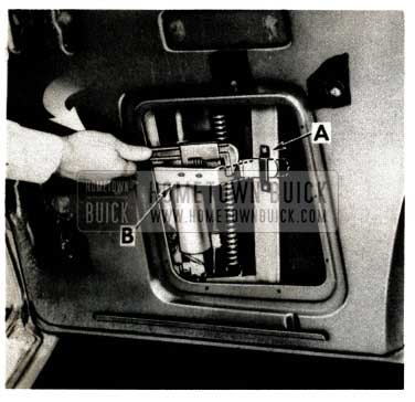
1952 Buick Hydro-Lectric Hydraulic Lift Spring Clip
CORRECTION:
- Bend the arm “B” away from the spring clip “A” to the position as shown for clearance in this area. (A 1/4″ bend is usually sufficient.)
- Obtain a new Door Window Hydraulic Lift Support Spring Clip (“A”), Group 10.782, Part No. 4614450.
- A loose spacer IS used in the “U” channel section of the frame stanchion and to prevent the spacer from dropping out, the new clip should be installed as follows:
- With a chisel, carefully cut off the upper attaching rivet for the spring clip “A” and install the new clip with one 1/4″ x 3/4″ long bolt, lock washer and nut.
- Repeat step 3 for the lower rivet location.
- Apply a coating of cup grease to the spring clip “A” and the arm “B”.
- The unused cage nut “C”, as shown in Fig. 113, rattles in its cage. This nut is incorporated for interchangeability between styles.
1952 Buick Hydro-Lectric Hydraulic Lift Cage Nut
CORRECTION:
Press 3-M Body Caulking Compound around the nut so it will be held firmly in the cage.
- On front doors of 4-door styles, the “forks” of the lower sash channel “D”(Figure 114) contact the arm “B” when the window is in the down position.
1952 Buick Lower Sash Channel
CORRECTION:
Adjust the window higher in the lift assembly until sufficient clearance is obtained in this area. The window must be adjusted so that it is not over 3/16” higher than the top of the belt molding at the aft end of the window opening, as shown in Figure 114.
- The cylinder wire connector “E”(Figure 113) slaps against the inner panel.
CORRECTION:
Tape the connector to the hydraulic tubing with a piece of waterproof tape.
HYDRAULIC FLUID LEAKS
1952 MODEL 46C
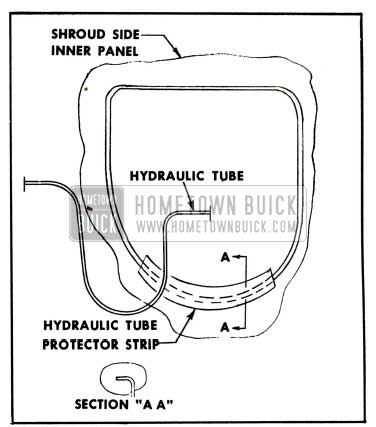
Hydraulic fluid leaks, in the 1952 Model 46C Convertible, may result from the hydraulic tubing rubbing against the edge of the cowl side inner panel access hole (See Fig. 115).
1952 Buick Hydro-Lectric Hydraulic Fluid Leak Locating
If this condition is suspected, it may be eliminated as follows:
- Remove cowl side kick pad and insulation.
- Cut a 5″ strip from a discarded piece of rubber weatherstrip.
- Split the rubber strip and cement it over the sharp flange in the access hole (View “A”, Figure 115) using 3-M Weatherstrip Adhesive or equivalent.
- Reinstall cowl side kick pad and insulation. This condition will be corrected in future production.
HYDRO-LECTRIC DOOR GROUND
1952 MODEL 46C
On some early production 1952 Special Convertibles (46C), the operation of the door windows is intermittent when windows are raised or lowered with the doors open. This condition has resulted from use of nylon bushings in the door hinges, which removes the positive ground formerly provided with the body through the hinges.
If this condition proves aggravating to owners, the following procedure may be used to install a positive ground on each door:
- Remove cowl side kick pad and insulation.
- Obtain a piece of No. 14 wire (woven and insulated) approximately 1.5″ long.
- Loosen hydro-lectric tubing conduit from door and wind one end of the wire, which has been stripped of its insulation, around the upper screw (“A” in Figure No.116) between the conduit and the door.
1952 Buick Hydro-Lectric Door Ground
NOTE: The surface of the conduit must be clean to insure a positive electrical contact with the ground wire.
WINDSHIELD WIPERS
1952 SERIES 40
We have uncovered some early 1952 Series 40 cars with incorrectly assembled windshield wiper motors and transmissions. In most cases, the 1951 motor has been used with a 1952 transmission, which causes one or both of the wiper arms to have an excessively long stroke.
The 1951 motor had a straight driving arm while the 1952 type has an offset in each end of the arm. For this reason, there is a 1/8″ difference in the stroke of the arms at the link attaching point.
We suggest that the possibility of interchanged motors and transmissions be checked whenever wiper trouble is initially encountered with 1952 Series 40 jobs. When making replacements in service, it is imperative to use the 1951 motor with the 1951 transmission and the 1952 motor with the 1952 transmission.
FRONT END SIDE RAILS
1949 MODEL 76R
Front End Side Rails (windshield posts) used on the 1949 Model 76R are no longer available and have been replaced by side rails specified for 1949 models 56C and 76C. These parts are identical except that the Convertible rails curve in at the upper edge and include the windshield header stud and plate. When using the Convertible rail on a Riviera, the curved portion at the top end should be cut-off at the Riviera weld line location, which is at the outside corner of the windshield.
Parts data is as follows:
1952 Buick Front End Side Rails Parts
TURRET TOP WRINKLES
1951 MODEL 410
We have had a few isolated cases, on the 1951 Model 41D, where the top assembly buckled in the center pillar area. When a condition of this type is encountered, it is necessary to install an additional body mounting at the No. 4 inner location and also to modify the center pillar to roof joint, so that a reoccurance will be prevented.
The following procedure should be used when performing this operation:
- Remove front seat assembly and remove, or turn-back, the front floor mat.
- Locate, on the floor pan, two positions which are 8″ forward of a center line drawn between the center pillars, and directly over the upper flanges of the frame side rails.
- Strip-back the floor pan insulation, at the points located in Step 2, and cut the floor pan as shown in Fig.117.
1952 Buick Floor Pan Insulation
Bend metal flap upward. The cutouts should expose the inside of the No.3 body crossbar (See Figure 120).
1952 Buick Body Crossbar
CAUTION: Do not allow bar to slip and damage the brake line that is clipped to frame.
1952 Buick Turret Top Wrinkles Correction
CAUTION: The bolt and washer must be installed in bottom of body crossbar. Under no circumstances should they be installed on the body floor pan.
- Install the rubber insulator washer, plain washer and lock nut, as shown in Figures 119 and 121.
1952 Buick Install Plain Washer and Lock Nut
1952 Buick Center Pillar
The following parts are required for this operation.
Do not use substitutes!
1952 Buick Turret Top Wrinkles Correction Parts
1952 Buick Turret Top Wrinkles Correction Required Parts
We do not expect to encounter this roof sag condition on the 1952 Model41D, because certain changes were made in the frame and center pillar construction.
RIVIERA TOP PANELS
1950-1951 MODELS 56R-76R
In order to reduce inventory and improve availability of parts, 1952 Model 56R-76R turret top panels will be supplied for service on 1950 and 1951 Rivieras. The principal difference in these parts is that 1952 panels have provisions, for installing the “flipper” type side roof rail weatherstrip, consisting of different locations for the attaching screw holes and absence of the countersunk holes required with 1950-1951 type weatherstrips. This does not indicate that the “flipper” seals should be installed on all 1952 panels, regardless of usage, because a considerable amount of additional reworking would be necessary to insure satisfactory installation.
When installing a 1952 top on a 1950 or 1951 model, it is necessary to drill new holes in the side roof rails to accommodate the 1950-1951 weatherstrip retainers. It is also necessary to flatten the countersunk attaching screw holes in the retainers so a tight fit against the roof rails will be obtained. The attaching screw heads will not be flush with the retainers, but; they will be absorbed by the rubber weatherstrips and appearance will be satisfactory.
DOME LAMP VIBRATION
1952 MODELS 56R-76R
A few cases have been uncovered on 1952 Model 56R and 76R Rivieras, where the dome lamp support on the roof bow vibrates against the roof panel and causes a “drumming” noise. This annoyance can be eliminated by the following procedure:
- Remove dome lamp assembly.
- Cut (2) sections of sponge rubber (rubber weatherstrip) of sufficient size to hold the dome lamp support assembly away from the roof panel (See Figure122).
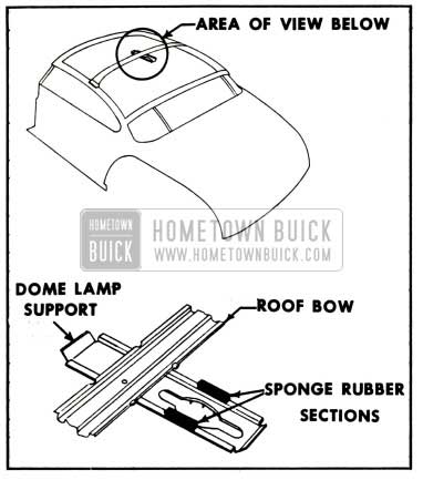
1952 Buick Dome Lamp Intallation
CAUTION: Use extreme care when installing rubber shims so dome lamp support will not be pulled away from the roof panel and cause a bulge downward in the headlining.
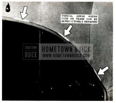
HEADLINING REPAIRS
Small cuts or tears in the headlining, adjacent to the windhose, can often be satisfactorily corrected without replacing the headlining assembly. Repairs in these areas (See Fig. 123) should be made as follows:
1952 Buick Headlining Repairs
- Pry the headlining retainer back and unhook the headlining from the retainer hooks.
- Cut a strip of matching cloth sufficient in size to cover the tear and provide additional gripping edge for the retainer.
- Cement the strip prepared in Step No. 2 to the underside of the headlining cloth where cut or tear exists, using 3-M Trim Cement or equivalent (See Figure 124).
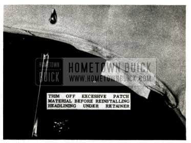
1952 Buick Headlining Trim Strips
Trim off excess patch material.
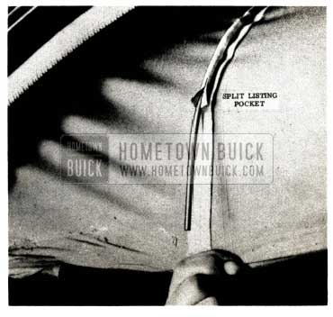
1952 Buick Headlining Listing Pockets
The pockets should be carefully split as required so that gradual and correct headlining contour is obtained. CAUTION: When splitting the listing pocket do not tear stitches that fasten pocket to headlining.
E-Z EYE WINDSHIELDS
1952 ALL SERIES
A percentage of the E -Z Eye Glass windshields installed since the start of 1952 production have been produced by an improved method whereas the shading of the plastic interlayer is accomplished by a printed process instead of the former dyeing process. This newly developed printed process assures consistant shading, thereby eliminating variations.
A distinct difference can be noted in the shading when comparing the two types, but they should be considered interchangeable from a service replacement standpoint, except on two piece windshields.
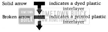
1952 Buick E-Z Eye Windshield Identification
Glass production facilities, for those cars being built with E-Z Eye Glass, will not permit 100% usage of the new printed material, however on such order, those cars equipped with two piece windshields are being equipped with the new glass.
Identification marks as follows are contained near the bottom of the shaded area at the outboard side of the windshield glass on two piece windshields and at the right side of one piece windshields.
SIDE MOULDING EXTENSION
1952 MODELS 52-72R
A few cases have been encountered where the body side moulding extension on 1952 Models 52 and 72R has a sharp point at the top forward edge. This condition is shown in Figure 126.
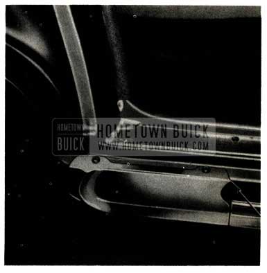
1952 Buick Side Moulding Extension
In order to avoid possible clothing damage when entering and alighting through the near doors, the sharp point should be rounded-off with a hammer.
In the future, it is advisable to check this condition during New Car Make Ready and to make the correction if necessary.
TRUNK LID DUSTLEAKS
1952 SERIES 50-70
Trunk lids used on recent production 1952 Series 50 and 70 models have drain holes located at the lower corners, between the weatherstrip and outer panel flange (See Fig. 127).
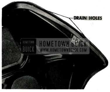
1952 Buick Trunk Lid Dustleaks
The holes were added to facilitate production and have no service function.
If there is a possibility that these holes are leaking dust into the rear compartment, they should be filled with. 3-M Body Caulking Compound.
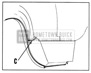
REAR QUARTER DUSTLEAKS
1951-1952 MODELS 45R-46C
In BPS 2.312, November 30, 1951, we published a procedure for minimizing dustleaks in the rear quarter areas of Series 40 Convertible and Riviera Coupes. This operation is now superseded by an improved method which involves installation of baffle valves over the rocker panel drain holes just ahead of the rear fender cut-outs. These valves, with necessary attaching parts, are available in kit form under Group 12.934, Part No. 4191187 Rear Quarter Panel Dustleak Kit.
The kit can be used on all 1951 Model 45R and 46C styles and also on approximately the first three months of 1952 production of the same models. Identification of applicable 1952 jobs can be made by examining the undersides of the rocker panels, which will have the drain hole set-up shown in Figure 128.
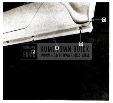
1952 Buick Rear Quarter Pinchweld Flange
The procedure for sealing the rocker panels and installing drain hole baffle valves is as follows:
- Seal any openings along the pinchweld flange, “A” in Figure 128, with 3-M Underbody Sealer
- Seal the lanced hole “B”, on the underside of the rocker panel, as follows:
- Clean the area of dirt.
- Flatten the forward embossed metal of the lanced hole “B”.
- Cement a strip of waterproof tape over the hole, using 3-M Weatherstrip Adhesive.
- Brush or spray Underbody Sealer over the tape.
- Seal the joint between the metal panels in the wheelhouse, “C” in Fig. 128 and 129, as follows:
1952 Buick Rear Quarter Metal Panels
- Clean all dirt from the area.
- Pack 3-M Body Caulking Compound in the joint.
- Brush or spray Underbody Sealer over the Caulking Compound.
- Clean the area of dirt.
- Flatten the forward embossed metal of the lanced hole “D”.
- Brush 3-M Weatherstrip Cement on the top surface of the rubber baffle valve near the edges only. The “flap” in the center of the valve will not operate correctly if cement is applied to it or to its opening.
- Locate the rubber baffle valve so that the flap is centered over the lanced hole and pointing toward the rear (See Figure 130).
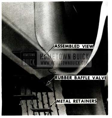
1952 Buick Baffle Valve
DI-NOC TRANSFERS
1950 THRU 1952 ESTATE WAGONS
The following procedures should be strictly observed in order to assure satisfactory application of “Di-Noc” transfers to Estate Wagon body panels:
APPLICATION OF “DI-NOC” TRANSFERS TO STEEL DOOR PANELS
- Prime coat any damaged part of panel with an air dry primer and sand entire surface after primer is dry.
- Spray or brush No. K-99 Di-Noc Bonding Coat over primer and allow to air dry one hour. If infra-red lights are used, they should be located 2 feet from panel and bonding coat should be dried for 20 minutes. When bonding coat is dry, wet sand with 6/0 “Wetordry” sandpaper and wipe clean.
- Mix a solution of 40% No. A-1169 Di-Noc Welding Solution and 60% water.
- Immerse the transfer in tepid water for approximately 1 minute to loosen the paper backing. CAUTION: Do not remove the paper backing, which is white in color, until after transfer has been applied to door panel.
- Saturate a small cloth pad with solution mixed in Step No.3, and apply to door panel. CAUTION: Any excess solution that runs down on adjacent door panel must be immediately wiped away.
- Apply wet transfer to adhesive on door panel, with paper side out. Allow about 1/2” overlap at door edge so that edge of transfer can be cemented to underside of door flange.
- Sponge entire area of applied transfer with clear water to remove all traces of paper backing adhesive. NOTE: When application of the transfer to the door panel is begun, it must be followed through to completion before adhesive begins to set.
- Use a rubber “Squee-Gee” (about1/4″x2″x 3″) and, with an overlapping stroking motion, level out the transfer from the center toward the outer edges. All wrinkles and air must be squeezed out to insure a firm bond. Use clear water as a lubricant for the “Squee-Gee”.
- Allow transfer to air dry at least 4 hours (or 1 1/2 hours if lamps are used) and brush or spray a coat of clear varnish. Allow varnish to air dry overnight.
APPLICATION OF “DI-NOC” TRANSFERS TO WOOD GROOVES
- Sand groove smooth and brush No. K-99 Di-Noc Bonding Coat in the groove. Allow to air dry 1 hour.
- Lightly dry sand bonding coat with 6/0 “Wetordry” sandpaper and wipe clean.
- Apply “Di-Noc” transfer using same methods outlined in Steps No. 3, 4, 5, 6, 7 and 8, of procedure for applying “Di-Noc” transfers to steel door panels.
- Immediately after using “Squee-Gee” to set transfer in place, use a sharp razor blade to trim all surplus transfer at edges of groove.
- Allow transfer to air dry at least 4 hours (or H2 hours if lamps are used) and brush or spray a coat of clear varnish. Allow varnish to air dry overnight.
Di-Noc No. K-99 Bonding Coat and No. A-1169 Welding Solution are available in one quart quantities from the Ionia Manufacturing Company, Ionia, Michigan. “Wetordry” sandpaper is a trade name of the Minnesota Mining and Manufacturing Company and is available through 3-M jobbers.
GOLDEN SAND PAINT
Approximately April 15, a change will be made in the mixing formula for Golden Sand, resulting in a slightly darker shade. The new paint will be identified by a change in Duco code number and Buick Paint Combination Numbers as follows:
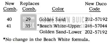
1952 Buick Golden Sand Paint Code
*No change in the Beach White formula.
TEAL BLUE PAINT
Two new color combinations are now being used in production, replacing the Surf Blue combinations. Duco information is as follows:
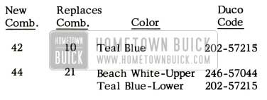
1952 Buick Teal Blue Paint Code
“METAL WRAP” COATING
ALL MODELS
The following procedure is recommended for removing “Metal Wrap” protective coating from service replacement body panels:
- Completely remove the “Metal Wrap” coating from the panel with mineral spirits, kerosene or enamel reducer and clean rags. All hemming flanges, corners, etc., must be thoroughly cleaned.
- Wipe the entire panel with a solvent cleaner such as “Prep-Sol”, “Pre-Kleano and Wax Remover”, or equivalent.
- Sand the bare metal with 320 sandpaper.
- Wash the panel with a metal conditioner such as “Metalprep”, “Metal Conditioner”, “Dioxidine”, or equivalent. Follow the manufacturer’s directions for applying the specific material used.
NOTE: After completing Step No. 4, the metal surfaces should not be touched with the hands and should be primed within five minutes. If panel is not primed shortly after cleaning, Step No. 4 should be repeated before priming.
- Prime and paint the surface in the usual manner.
MAINTENANCE OF BRIGHTWORK
Some servicemen are apparently not aware that the plating process used on interior chrome fittings and parts has also been affected by material restrictions.
Most of these parts are protected by a clear baked enamel and it is extremely important to avoid the use of solvents or abrasives for cleaning and polishing. When the enamel has been scratched or removed, the protection is gone and it is necessary to make repairs within a reasonable length of time in order to prevent further deterioration.
No attempt should be made to repair minor scratches or mars. If the enamel is broken through in a large enough area to make repairs necessary, we recommend the following procedure:
- Feather the edges with a small amount of “Rotton Stone” on a wet cloth or felt. Care should be taken to avoid enlarging the area any more than necessary. (Rotton Stone is available in cake or powder form at most drug stores).
- Clean the damaged section with naptha or a commercial cleaner such as “Prep-Sol”.
- Carefully mask adjacent parts or panels.
- Spray or brush two coats of Dupont No. 1234. Clear, allowing suitable drying time between coats.
Occasionally we receive letters from dealers and owners, asking us to differentiate between exterior chrome plated and stainless parts so that proper protective measures can be taken. As a rule, all die cast parts are plated but there are a number of stainless mouldings, particularly on Series 70 cars, that also have a chrome flash.
Because of the possibility that material restrictions may cause specification changes from time to time, we do not want to establish certain parts as critical from a maintenance standpoint, to the exclusion of others. Whenever Buick Chrome Preservative is applied, equal attention should be given all “brightwork” regardless of whether plated or not. In this way, we can be sure that an absolute minimum of corrosion will take place.
Interior bright work is ordinarily not subject to corrosive conditions and the use of Buick Chrome Preservative, and other protective preparations, should be avoided due to the possibility of staining upholstery fabrics and clothing.
Leave A Comment
You must be logged in to post a comment.