1951 ENGINE NUMBERS
The following are 1951 Buick starting Engine numbers:
Series 40 – Synchromesh – 6240128-4; Dynaflow – 6240100-4
Series 50 – Synchromesh – 6240564-5; Dynaflow – 6240100-5
Series 70 – Dynaflow 6240161-7
1951 SERIAL NUMBERS
The following are 1951 Buick starting Serial numbers:
Flint – 16031301
Southgate – 26050001
Linden – 36055001
Kansas City – 46061001
Wilmington – 56070001
Atlanta – 66075001
Framingham – 76080001
COLLAPSED RADIATOR HOSE
1951 SERIES 70
We have received some reports of overheating on 1951 Series 70 cars, caused by collapse of the lower radiator hose (lower tank to water pump).
Further investigation reveals that some lower hoses got into production without inclusion of the coil type inner spring. If this condition is encountered, the hose should be replaced. There is also a probability that the spring is not full length in some hoses, causing a “kink” in the unsupported section of the hose. This condition can usually be corrected by relocating the spring so that the critical areas of the hose are properly supported.
NEW OIL FILTER CAN
A new style engine oil filter can will be used in the near future on all 1951 production. The new can differs from the present style in that a drain plug is not provided in the base and the base is formed in a concave cone.
When servicing the new style filter, the oil should be removed with a suction pump and all sludge or other foreign matter removed by thoroughly wiping with dean cloths. If necessary, the can should be removed and washed in kerosene prior to wiping. Caution: Never use the same suction pump for removing oil from filters and filling shock absorbers. A small particle of foreign matter, removed from the filter and transferred to a shock absorber, will plug the shock valves.
The Parts Department will continue to supply the present Group 1.836, Part No. 5572493 Oil Filter Package for replacement of all new style filters.
RADIATOR TANK-TO-CORE LEAKS
ALL MODELS WITH HARRISON RADIATOR
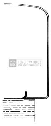
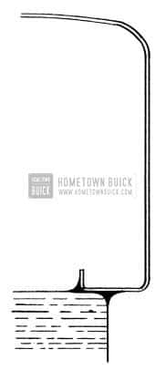
Tests conducted by the Harrison Radiator Division have shown that an added fillet of solder at the outer edge of the radiator core, where it is joined to the tank, adds considerable strength to the joint and will help to reduce leaks in this area. The normal soldering method is shown in Figure 1 and the added fillet, which is recommended when repairing upper tank-to-core joint leaks in service, is illustrated in Figure 2.
1951 Buick Upper Tank to Core Joint
1951 Buick Radiator Tank-to-Core Leaks
The following repair procedure is suggested:
- Clean thoroughly and sweat solder into leaking area in the normal manner with torch and flux.
- Thoroughly chill the soldered area with flux or water.
- After chilling, build up a fillet as shown in Figure 2. This is best accomplished with a hatchet-shaped soldering copper, but it can also be built up through careful application of solder with a torch.
Dealers who do not maintain radiator repair facilities should request this method of soldering the tank whenever a radiator is returned to an Authorized Harrison Radiator Service Station for correction of tank-to-core leaks.
OVERSIZE “RE” ENGINES
The Engineering Department has recently approved the use of .010″ oversize cylinder bores in replacement engine assemblies. In line with regular production engine procedure, all .010″ oversize replacement engines will have a stamped dash (-) about 1/4″ long directly following the replacement engine number.
Oversize replacement crankcase assemblies will have a ”+10″ stamped on the crankcase adjacent to the oil dip stick.
The use of .010″ oversize bores will not affect the performance, quality or overall life of the engine.
LIFTERS NOISY ON “IDLE”
ALL SERIES WITH HYDRAULIC LIFTERS
In some cases, prolonged idling of 1951 engines with hydraulic valve lifters may cause the lifters at the front of the engine to become noisy. Due to the pitch of the engine in the chassis, oil flow in the rocker arm shaft is toward the rear and the front lifters become the last to receive an oil supply. This condition is aggravated when the car is parked or stopped on an incline.
When complaints of this nature are received, the possibility of inadequate oil supply to the lifters should be checked by noting whether oil is being ejected from the bleed hole, under the push rod shroud, on all push rods when the engine is idling. Care should be exercised when making this check because the bleed hole may be on the back side of the push rod and oil ejection may not be readily apparent.
If oil is ejected in any amount from all bleed holes, the oil supply can be considered normal. If oil is not being ejected from the front push rods, the rocker arm shaft oil supply should be checked by prying the oil inlet pipe from the top of the No. 1 rocker arm shaft bracket. U oil does not flow from the pipe in good volume, the engine should be stopped and the restricted overhead oil line fitting removed from the cylinder head. The hole in this fitting should pass a #56 drill and should be free of burrs. If the fitting passes this inspection, and the overhead oil pipe is free; but, front lifters continue to “pump down”, the hole in the restricted fitting should be enlarged with a #50 drill.
CAUTION: The possibility of oil starvation at the front lifters has now been eliminated in production by reducing• the diameter of the push rod bleed holes. Since it is impossible to determine the size of the hole, the restricted fitting should not be enlarged unless it is definitely known that the front lifters are not receiving an oil supply when the engine is idling. In addition, a drill larger than #50 should not be used to enlarge the restricted fitting. Indiscriminate application of this suggested correction will very likely result in an oversupply of oil to the valve stems with an accompanying increase in oil consumption.
SERVICE PISTON RINGS
1940 THRU 1950 ALL SERIES
We have been informed by the Parts Department that some Service Piston Ring Sets, Part Nos. 1338431, 1338432, 1338433 and 1338434 are being returned to warehouses by dealers because the package does not include shims for the No. 2 ring groove.
This is to advise that the piston ring manufacturer has recently changed the design of the No. 2 ring expander so that use of a shim is unnecessary, and has accordingly been omitted from the sets.
ALUMINUM PISTONS
1951 SERIES 40 DYNAFLOW AND ALL SERIES 50
Effective with August 7th engine production, all Series 50 engines will again be equipped with aluminum pistons and a high compression cylinder head. At the same time use of aluminum pistons will resume in some Series 40 Dynaflow jobs, but all Series 40 Synchromesh engines will continue
100% usage of cast iron pistons. As in the past, there will be no field identification of Series 40 Dynaflow piston types. All Series 40 engines will, however, continue to have the lower compression cylinder head regardless of piston type.
HYDRAULIC VALVE LIFTERS
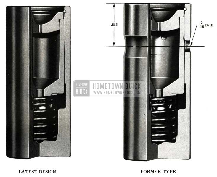
Redesigned hydraulic valve lifters went into production March 26 in Series 40 Dynaflow, Series 50 and 70 and Replacement engines. From the comparison of new and past type lifter assemblies (Figure 3) it will be noted that the oil grooves and bleed holes have been removed from both the lifter body and the plunger.
1951 Buick Hydraulic Valve Lifters
The new lifter assemblies will carry Part No. 5230610 and are completely interchangeable with past style lifters. It is permissible to intermix any of the past and present production style lifters in the same engine.
Effective engine numbers for field identification purposes are as follows: (Add the suffix 4, 5 or 7, depending upon Series car.)
Series 40-50 Dynaflow – 6353330 to 6355499 Inclusive
Series 50 Synchromesh – 6353594 to 6355499 Inclusive
Series 70 – 6353331 to 635.5499 Inclusive
All Series – 6360478 Continuous
Series 50 RE – 161200 Continuous
Series 70 RE – 512374 Continuous
ALUMINUM PISTONS
1951 SERIES 40-50
Authority has been granted to resume use of aluminum pistons in Series 40 and 50 engines on a 100% basis. Coincident with this change, the cylinder head and gasket types and combinations will conform with assemblies used at the start of 1951 production. All engine specifications listed in the 1951 Shop Manual will, therefore, again be effective with the following engine numbers:
Series 40 Synchromesh – 6585179 Continuous
Series 40 Dynaflow – 6591660 to 6595299 Inclusive; 6597116 Continuous
Series 50 Synchromesh – 6514127 Continuous
Series 50 Dynaflow – 6505495 to 6506699 Inclusive; 6512778 Continuous
Since approximately the last week of February, we have gone through several transition periods with regard to pistons. At various times, cast iron pistons were used 100% and during others, on a percentage basis. There is no method for external identification of piston types so we ask that dealers refrain from referring owners to the factory for this information.
CAST IRON PISTONS
Due to material restrictions recently imposed, all Series 40 Synchromesh jobs will be equipped with cast iron pistons. This change will take effect about March 1 and at time of printing, we do not have the initial engine number. This information will, however, be published in a future bulletin as soon as the number is definitely ascertained.
Cast iron pistons can be identified, in addition to increased weight, by the presence of bronze piston pin bushings and oval shaped depressions at the outside piston pin locations. (Aluminum “F-263” pistons have rectangular depressions with an embossed part number and “Buick” designation.) In addition, cast iron pistons will be given the “Lubrite” treatment instead of being “anodized” as is the case with aluminum pistons.
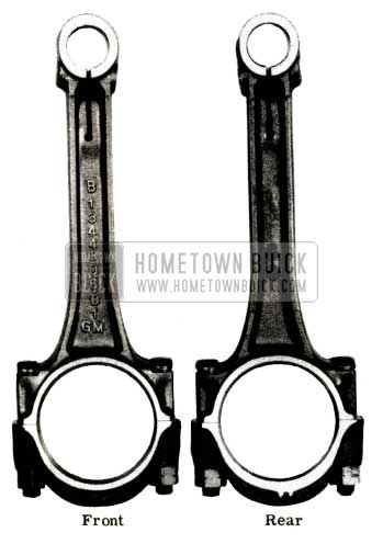
Connecting rods and caps used with cast iron pistons will have a different material specification to adapt them to the increased weight of the pistons. Rods will have two raised dots, .440″ apart, on the rear face and the embossed forging number 1344306 on the front face. (Rods used with aluminum pistons have one dot and the number 1339643). The rod caps will be identified by two ribs on the rear face. It is essential that mating rods and caps be used. In other words, do not use caps designated for aluminum pistons with the new connecting rods.
Cast iron and aluminum pistons cannot be intermixed in the same engine because the weight differential will affect engine balance.
In the event that parts availability problems are encountered in the field, it is permissible to use aluminum pistons with connecting rods and caps designated for cast iron pistons. Do not, however, use cast iron pistons with rods and caps designated for aluminum pistons.
Cast iron pistons and mating rod and cap assemblies are not available for service at this writing. When these parts do become available, the field will be notified by means of a regular parts book supplement issued by the Parts Department.
Parts information for pistons, rods and caps to be used with Series 40 Synchromesh jobs, when equipped with cast iron pistons, is as follows:
Piston pins and connecting rod bearings are not affected by this change and will remain as used on present “F-263” engines.
CAST IRON PISTONS
In connection with the use of cast iron pistons in Series 40 Synchromesh engines, the connecting rod assembly photo, Figure 4, is shown to assist in field identification. The location of the raised dots on the rear face of the rod and the two ribs on the rear face of the cap should be noted.
1951 Buick Cast Iron Pistons
The use of cast iron pistons was extended to some Series 40 Dynaflow and Series 50 Synchromesh and Dynaflow engines April 2nd. Present plans call for 100% usage in these jobs by May 1st, or shortly thereafter. In conjunction with this change a lower compression cylinder head, .020″ thicker than heads currently used, will become standard on all Series 40 and 50 engines. This head will provide more satisfactory operation with cast iron pistons and no optional higher ratio will be available. The new cylinder head can be identified by a letter “L” stamped at the right front side of the head, under the overhead oil line fitting. You will recall that this was the location of the identifying mark on 1950 Series 40 Dynaflow heads.
During the transition period, all engines will not carry cast iron pistons nor will they all be equipped with the lower compression cylinder head. You may be assured, however, that all engines with cast iron pistons will also have the low compression head.
There will not be any method of identifying piston types in individual engines. This should not cause any service problems as piston types are readily identifiable when the engine is “torn down.” Other than owner curiosity, we cannot see any reason why piston type identification is important when the car is delivered, or during subsequent light service operations.
Piston and connecting rod assemblies will be identical to those now used in Series 40 Synchromesh engines and all previous information published relative to cast iron pistons is also applicable to this latest usage.
Cast iron pistons are now being used 100% in Series 50 jobs equipped with Synchromesh transmission. This change was effective with Engine Number 64477545.
LICENSE PLATE LOCATION
1951 ALL SERIES
Under certain operating conditions, it is possible for the front license plate on 1951 models to hinder adequate engine cooling. If this condition is encountered, the license plate should be moved to a new location similar to that used in 1950. The suggested installation procedure is as follows:
- Remove the license plate and bracket as an assembly.
- Replace bracket bolts in bumpers.
- Place the bracket and plate assembly in a level position (shown in Figure 5) and locate bracket holes.
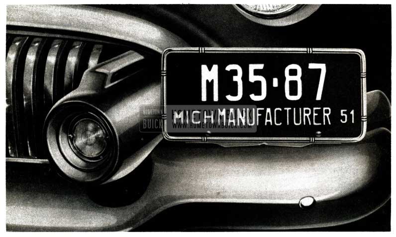
1951 Buick Licence Plate Location
Allow approximately 1/2″ clearance between license plate end and bumper guard (bomb) and 1″ clearance between back of plate and upper grille bar extension.
CRANKCASE VENTILATOR 80DY
The crankcase ventilator outlet body, that is an integral part of the valve push rod cover assembly Group 0.439, Part Nos. 1331770 (40-50) and 1331768 (70), has recently been redesigned (See Figure 6).
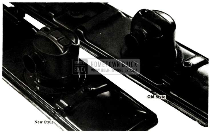
1951 Buick Crank Case Ventilator Body
If push rod covers having the new style ventilator body are used on 1948 or 1949 models, interference will develop between the ventilator body and the oil filter bracket. In such cases it will be necessary to use two or three standard 5/16″ flat washers as spacers between the body and bracket (Figure 7) and longer No. 2 push rod bolts to insure sufficient thread engagement.
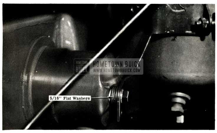
1951 Buick Crankcase Flat Washers
Series 40-50 engines will require a 5/16″ – 18 x 5 1/4″ bolt and Series 70 jobs will require a 5/16″ – 18 x 5 5/8″ bolt. These bolts are not stocked by Buick Parts Warehouses and should be obtained locally.
Leave A Comment
You must be logged in to post a comment.