1952 BUICK ENGINE MAINTENANCE
SERIES 70
Engine refinements provide 1952 Series 70 cars with brilliant performance and reduced fuel consumption at usual operating speeds.
A 7.5-1 compression ratio in conjunction with the new four barrel carburetor provides the following specifications:
Maximum brake horsepower: 170 at 3800 RPM
Maximum brake torque: 280ft .lbs. at 2400 RPM
Compression ratio: 7.5-1
Compression pressure: 120 lbs. at cranking speed
The higher compression ratio is accomplished by shaving stock from the cylinder head (Part No. 1343707), and the .050″ thick cylinder head gasket used in 1951 will be retained.
Proving Ground tests indicate considerable improvement in acceleration characteristics, particularly in the 10 to 60 and 40 to 60 mile per hour speed ranges. The fuel economy increase ranges from 1.4 miles per gallon at 30 miles per hour to .5 miles per gallon at 60 miles per hour.
HYDRAULIC LIFTER TEST
We have received numerous reports that some dealers are using leakdown mixtures, in their hydraulic valve lifter test fixtures, that differ from the mixture specified in the lifter school. Some of these reported mixtures contain engine oil or brake fluid. It is suggested that this practice be discontinued and the mixture recommended in the school be used. In the event that your Hydraulic Lifter Manual was not corrected during the school, it is recommended that you make the following correction at this time to page 11, second column, last paragraph:
Prepare a special test fluid by placing 20 ounces of Buick Dynaflow oil in a clean and accurate one gallon container, fill container to the one gallon mark with kerosene, then stir or shake the container to thoroughly mix the oil and kerosene. The only possible way that consistent readings can be obtained is through the use of Buick Dynaflow oil and kerosene.
This matter is brought to your attention because the leakdown fixture definitely will not work satisfactorily unless the correct leakdown mixture is used. In order to promote a better understanding of the problem, the following information is given.
The leakdown fixture was designed and calibrated for use with a specific fluid of known viscosity.
It was designed to test how fast a lifter plunger will fall under certain controlled conditions; two of the conditions being that a 50 lb. force be exerted on the plunger and that the leakdown fluid have a known constant fluid rating at room temperature.
When a lifter is checked for leakdown, the time it takes for the fluid to pass between the plunger and the body, and the ball and ball seat is determined. Therefore, if the leakdown mixture is too thick the leakdown rate is inaccurate and will be too slow; if the mixture is too thin, the leakdown rate is inaccurate and will be too fast.
The acceptable leakdown rate of 9 to 38 seconds as published in the Hydraulic Lifter Manual was established and based on the use of correct leakdown fluid. You cannot accurately determine the fluidity of a mixture other than by laboratory methods, therefore, it is not practical to use other mixtures and assume that the same leakdown rates will hold true.
The Buick Dynaflow oil mixture was developed and recommended because it was proven by tests that the fluidity of this mixture remained constant, within practical limits, at room temperature and this oil is readily available to all dealers.
At the time the Hydraulic Valve Lifter Training Program was presented, it was stated that a new ball should be used in every reconditioned lifter. Since that time it has been found that some dealers are using bicycle balls, distributor race balls and balls purchased from independent sources. These balls are not accurate enough for lifters. Whenever a thorough cleaning job is done on an engine and lifters are thoroughly reconditioned, and an intermittent rap develops as soon as the owner leaves the shop, it would indicate that one or more lifters have a defective ball or ball seat on the plunger. It is for this reason that we request all dealers to use balls furnished through the Buick Parts Department. Balls are very difficult to inspect and this will provide a sure means of obtaining the best commercial carbon ball available.
When cleaning hydraulic valve lifters, always brush the inside of the body and rinse it thoroughly.
When the bore of the body is inspected, always look at the bottom of the bore to see if any metallic particles are adhering to the surface. Sometimes flat pieces of metal or other foreign material will stick to the bottom due to adhesive action. These particles are very difficult to remove but will cause an intermittent rap if they are allowed to remain in the lifter.
The frost condition on plungers which is covered on page 10 of the Hydraulic Lifter Manual means “DEFINITE SCORE MARKS” that can be felt with the fingernail. The marks do not cover much of the plunger area but are rough and vary from approximately 1/16″ to 1/8″ in diameter. Lifter plungers with this condition will seize when hot and release again as soon as the engine oil temperature lowers. A plunger which appears to be frosty over half or all of its entire area but which is not rough enough to be detected with the fingernail, will run satisfactorily as long as the leakdown rate and ball travel meets specifications.
For your information in every case where dealers complained that the fixture and procedure were not doing a good job, one or all of the above reasons were found to be the cause by factory personnel making investigations in the dealerships.
We are thoroughly convinced that if the procedures in the lifter manual are followed to the letter, you will eliminate 99% of the hydraulic lifter noise repeat complaints
SERVICE CONNECTING RODS
1951 SERIES 40 – 50
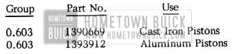
When cast iron pistons were originally used in 1951 Series 40 and 50 engines, the material specifications of the connecting rods and rod caps were changed to compensate for the increased piston weight. In order to eliminate •the possibility of the incorrect rods being used, it was decided to stock only the strengthened type for all service replacements. The original rod assemblies, for use with aluminum pistons, are again available and will be supplied in addition to the cast iron style. Extreme care must be exercised to ensure that the correct rods are used in engines having cast iron pistons. Identification can be made as outlined on Page 4 and 5 of this 1951 -52 BPS Abridged Edition.
Correct connecting rod ordering information for 1951 Series 40 and 50 jobs is as follows:
1952 Buick Service Connecting Rods Parts
PRECISION TYPE CONNECTING RODS
1937-48 SERIES 40-50; 1936-48 SERIES 70
It has been brought to our attention that some service men are reluctant to install precision type connecting rods in Series 40-50 engines built from 1937 thru 1948 and Series 70 engines built from 1936 thru 1948. As a result, they are buying spun Babbitt type rods from outside suppliers. Some of these replacement rods may not meet original specifications and their use may result in engine out-of balance or premature bearing failure.
The precision type rods with replaceable bearings are the same weight as the former spun Babbitt rods and both types may be used interchangeably either individually or in sets. It is not necessary to install all eight precision rods when only one or two spun rods require replacement.
HYDRAULIC VALVE LIFTERS
1952 ALL SERIES
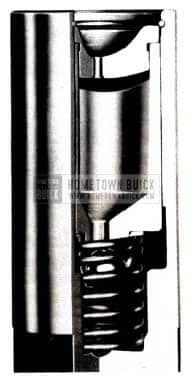
For approximately the last month all 1952 engines, except Series 40 Synchromesh, have been equipped with modified hydraulic valve lifters. The new lifters are undercut from the bottom of the lifter body upward for a distance of about 13/32″. (See Figure 3).
1952 Buick Hydraulic Valve Lifters
This change has been made to facilitate lifter removal during servicing and does not affect lifter operation in any manner. All current and past type lifters are completely interchangeable and may be intermixed in the same engine. The lifter part number will remain unchanged (5230610).
LICENSE PLATE LOCATION
1951-1952 ALL SERIES
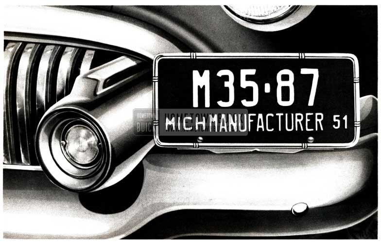
On 1951 models, operating under certain conditions, it was necessary to relocate the front license plate in order to provide adequate engine cooling. We wish to call your attention to the fact that this procedure is also advisable on similarly affected 1952 Models. The suggested method of relocation is as follows:
- Remove the license plate and bracket as an assembly.
- Replace bracket bolts in bumpers.
- Place the bracket and plate assembly in a level position (shown in Figure 4) and locate bracket holes.
1952 Buick License Plate Location
Allow approximately 1/2” clearance between license plate end and bumper guard (bomb) and 1” clearance between back of plate and upper grille bar extension.
CAR AND ENGINE NOISE
1951 – 1952 ALL SERIES
Product reports indicate noises caused by the engine, described as Woo- Woo, beat noise, vibration, etc. which show up at speeds from 30 to 80 miles per hour. The Woo-Woo or beat noise usually comes in at the lower speeds and the vibration periods range from low speed to extreme high speed.
Since no single part or unit of the car is consistently responsible for these conditions, we have outlined a procedure for methodically going thru the various parts which must be checked and found O.K. Each step must be followed carefully and completely so that you positively know that particular portion of the check is 100% O.K. For example one car the factory worked had supposedly been checked out and actually worked on for three days in the dealership. The engine was reported tuned and in good shape. The first thing the factory did was tune the engine and in doing so a compression check revealed two cylinders low. In removing the head two burned exhaust valves were found. When these were replaced the vibration and Woo-Woo (at 73 mph) were gone and the owner was satisfied. This story is just to illustrate that you can’t be too careful.
The first steps to be taken are as follows:
Noise Analysis
- Engine should be carefully and completely tuned up, checking compression, timing and spark plugs. Correct, if necessary.
- With car standing still and transmission in neutral or parked position, run engine through the range carefully and note the noise periods with tachometer registering the engine RPM.
If any objectionable noise is noticed during this check then proceed as follows:
Fan And Generator Noise
- Remove fan belt and run engine. If noise changes or is reduced it can be assumed that some of the noise is caused by the fan, generator, the fan belt, or conceivably the water pump.
- Check for undercoating on harmonic balancer and crankshaft pulley. Also check crankshaft pulley for wobble or run -out.
- Make sure there is no undercoating on fan belt, pulleys, fan blades and generator to cause out of balance.
- Check fan blades for excessive runout. Correct if necessary.
- Fan pulleys with abnormal runout or wobble should be changed.
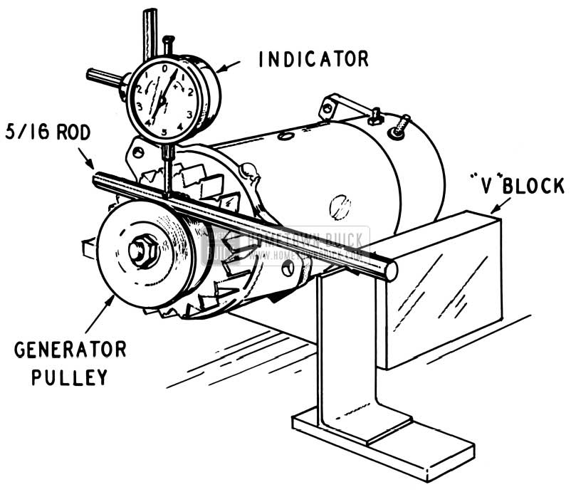
- Check generator pulley radial runout at belt groove (see recommended method in Figure 5).
1952 Buick Fan and Generator Noise Reduction
The maximum runout should be .010. Replace if necessary. Generator bracket may be bent causing generator and pulley to run in cocked position. Correct if necessary.
If noise is a moan or whine caused by generator it will decrease in intensity when the car lights are turned on. The only remedy for this is to replace the generator.
If the above does not correct the noise then we can assume that some of the noise may be produced by an out of balance condition in the engine or transmission. Then proceed as follows: (Also see Section 2-G, Page 2-49 of the 1951 Shop Manual).
Engine and Transmission Balance
- Remove flywheel housing cover and the inspection hole cover with a driver in car and car on the hoist. Dynaflow transmission in “Park” position.
- Number bolts in the flywheel with chalk Synchromesh 1 to 6, Dynaflow 1 to 15.
- Starting with any bolt, add weight (a 2nd. nut on Dynaflow jobs and flat washers on Synchromesh jobs) to bolt and check vibration period, noting engine RPM, and with fingertips on steering wheel observe the results for roughness.
- If the added weight increases the roughness then it can be assumed that the weights should be changed to another bolt. If the roughness has decreased then try more weight at the same location.
- To get the best results, keep a record of speed and roughness, changing weight from starting point to directly opposite or 180 degrees; then in a like manner to the quarter or 90 degrees position either side. When the proper out of balance position is located then it will only be a matter of determining how much weight to add to make the engine as smooth as is possible.
- If the job is smooth, remove nuts and install the equivalent amount of weight as per instructions in 1951 Shop Manual, Section 2-G, Page 2-49 on Dynaflow jobs. Re-check for vibration or noise to make sure the engine is still smooth. (Note: – The locking type nut used on bolt should not over-hang the end of the bolt, if necessary use thinner weights on more than one bolt.) You should then r-install the covers and check the car on the road for the items listed as “D” and “E”. Also check the lateral runout of the flywheel with transmission disconnected. This should not exceed .10”
- If the job is still noisy it will probably be necessary to examine engine or transmission parts and we suggest you report the condition to the zone service manager for further instructions.
Propeller Shaft Vibration
Drive car through the speed range and note the objectionable periods. If the period is at high speed (65 mph or higher), then it is an indication that the propeller shaft is out of balance (either oil in shaft or a crooked shaft).
To determine positively if the propeller shaft is causing the vibration, shift the transmission in 2nd gear or low range and drive car at same engine speed as it was when vibration was noticed in direct transmission speed. To determine the same engine speed required, divide the car speed by the transmission ratio using 1.6 for Synchromesh and 1.8 for Dynaflow when in 2nd or low speed range. (Example: If vibration comes in with transmission in high range at 65 miles per hour, then the vibration should come in at 65 + 1.6 = 40 miles per hour in 2nd speed with a Synchromesh and 65 + 1.8 = 36 miles per hour in low range with a Dynaflow transmission.
If the vibration is still present at the same engine speed in either direct or low range speed then the propeller shaft is not out of balance.
If the vibration decreases or is eliminated then the propeller shaft is out of balance and should be removed, checked for oil in shaft and straightness of shaft. Make the necessary corrections. “See 1951 Shop Manual, Section 5-C, Page 5-18”.
General Car Vibration
- Check tires for balance and runout, also for scallops, flat spots or uneven wear. Correct if necessary. If there is any possibility that tires may be causing the trouble inflate the front tires to 50 lbs. and recheck on road at critical speed.
- Check wheel bearings.
- Check exhaust system for interference with body or chassis. Correct if necessary.
- Check all sheet metal and bumpers, bumper back bars, etc. for interference. It is also possible for a stone or pebble to become lodged between critical units of the car such as frame and body, thus transmitting noise and vibration which would ordinarily be dampened by the natural design of the car.
- Loosen up all motor, transmission, and body mountings; drive car approximately two miles over fairly rough pavement and re-tighten mounting bolts to correct torque specification. (Note: It may be necessary to add shims before tightening bolts in order to maintain the natural positions and alignment that the units have obtained during the shakedown run.)
- It also is advisable to check the torque ball and universal joint for free action. If there is any bind at this location it is very liable to cause a sprung condition in the propeller shaft which may bring about a forced out of balance.
Please report the results you have obtained by following this bulletin to your zone service manager.
6 BLADED FAN
70 SERIES ONLY
It has been brought to our attention that the Series 70, under certain adverse conditions, is overheating. This condition is prevalent with metropolitan drivers who must operate at excessively low speeds, with numerous starts and stops, for extended periods of time.
A limited number of special 6-bladed fans are now available which are effective in eliminating over heating due to slow air movement coincidental with slow driving. These fans may be ordered under (Group) 1.359, Part No. 1161825.
Installation and adjustment are the same as in previous procedure, tightening the fan belt as required to eliminate slippage.
Under certain high R.P.M. engine operation, the 6 bladed fans’ noise is noticed. This operational noise is slightly more than the standard 4-bladed fan, due to the increase in air volume being moved. Its effectiveness more than compensates for this negligible condition.
SERIES 70 FAN
1951 – 1952 SERIES 70
Correction to Par. 2-2 (g.), 1951 – 1952 SM Specifications appearing on Page 2-3 of the 1951 and 1952 Shop Manuals indicate that Series 70 cars use a five-bladed fan. Actually, a four bladed fan was adopted shortly after the start of 1951 production and was carried through into 1952 production. As a result, the Master Parts List specifies only the four-bladed type and it should be used for all service replacements.
Hi, I need to know for the connecting rod 263 engine the rod big end diameter