SECTION 4-B 1954 BUICK SYNCHROMESH TRANSMISSION AND UNIVERSAL JOINT
4-7 1954 BUICK SYNCHROMESH TRANSMISSION AND UNIVERSAL JOINT SPECIFICATIONS
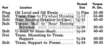
Tightening Specifications
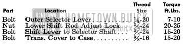
1954 Buick Synchromesh Transmission Tightening Specifications
1954 Buick Synchromesh Transmission Specifications
1954 Buick Synchromesh Transmission Specifications
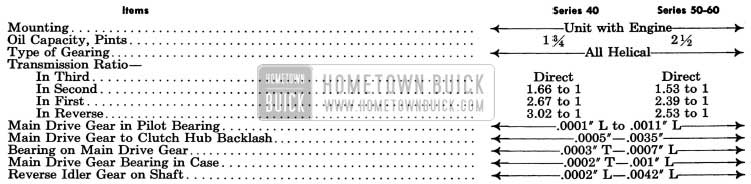
1954 Buick Synchromesh Transmission Specification
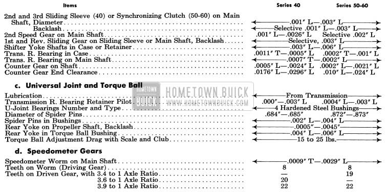
1954 Buick Universal Joint and Speedometer Gears Specifications
Universal Joint and Torque Ball (see above)
Speedometer Gears (see above)
4-8 1954 BUICK SYNCHROMESH TRANSMISSION DESCRIPTION (SERIES 40)
The Series 40 Synchromesh transmission is smaller and of different design than the Series 50-60 transmission.
The 1954 Buick Synchromesh Transmission is solidly bolted to the rear face of flywheel upper housing, with a heavy paper gasket between, to form a unit assembly with the engine. The transmission main drive gear extends through the clutch driven plate into a single-row-ball pilot bearing seated in the rear end of engine crankshaft. The outer race of main drive gear bearing projects from transmission case to seat in a counterbore in flywheel housing, thus serving as a pilot to center the transmission with engine crankshaft.
1954 Buick Synchromesh Transmission Gears and Shafts
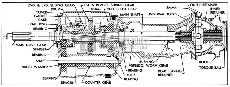
The 1954 Buick Synchromesh Transmission main drive gear is supported by a ball bearing seated in front wall of transmission case. The ball bearing, which is shielded on rearward side, is pressed against a shoulder on main drive gear and held in place by an oil slinger, washer, and retainer (snap ring). The outer race of bearing is grooved for a snap ring which fits between transmission case and flywheel housing to hold bearing and main drive gear in place. See figure 4-17.
1954 Buick Series 40 Synchromesh Transmission
The front end of transmission main shaft is piloted in the bored rear end of main drive gear by a bearing consisting of 14 small steel rollers, which are retained in drive gear by a washer and snap ring. The main shaft is also supported by the transmission rear bearing which seats in transmission rear bearing retainer. The outer race of rear bearing is held in position by a shoulder in bearing retainer and a lock (snap ring) which engages a groove in retainer. The inner race of bearing is retained between the main shaft thrust washer and a snap ring seated in a groove in shaft. A bushing in rear bearing retainer supports the main shaft just forward of the universal joint.
The 1954 Buick Synchromesh Transmission counter gear is supported by two roller bearings on a shaft which is held stationary in transmission case by a steel ball seated in recesses in case and rear end of shaft.
A tubular spacer and two thrust washers are located between the roller bearings, and a retaining washer is located at outer end of each bearing to hold the rollers in position. End thrust is taken by a bronze thrust washer at each end of counter gear. A hole in hub of counter gear permits lubricant to reach bearings and thrust washers. See figure 4-17.
The reverse idler gear is provided with two bronze bushings and is supported on a shaft which is held stationary by a grooved pin lock driven into holes in transmission case and rear end of shaft. End thrust is taken by a bronze thrust washer at each end of idler gear. Lubricant is fed to thrust washers and bushings through passages in 1954 Buick Synchromesh Transmission case and a groove cut through the bore of idler gear.
The second speed gear is mounted on the main shaft between two thrust washers and a snap ring, which hold it in position to mesh with the counter gear. It is free to rotate on the main shaft except when engaged by the second and third speed sliding sleeve during second speed operation. The sliding sleeve is splined to the main shaft to transmit drive when sleeve is engaged with either the main drive gear (third speed) or the second speed gear. The sliding sleeve carries the first and reverse sliding gear on splines so that it also transmits drive to the main shaft in first speed and reverse. See figure 4-17.
1954 Buick Synchromesh Transmission Gear Shift and Synchronization
The gear shift mechanism in the Series 40 and the Series 50-60 transmissions are so similar that they are described together in paragraph 4-10.
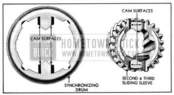
1954 Buick Synchromesh Transmission gears are synchronized only when shifting into second and third speeds. When the transmission is shifted into second or third speed, the sliding sleeve and the gear it engages are synchronized in speed through the action of a synchronizing drum. Each drum is a steel stamping having a bronze insert machined to match a conical surface on the gear, to which drum is loosely attached by a wire retainer. Synchronization is obtained when the bevelled cam surfaces of the two slots in sliding sleeve come in contact with the bevelled cam surfaces on the two fingers of synchronizing drum. See figure 4-18. This contact of cam surfaces presses the drum against the gear so that gear is brought to the same speed as the sliding sleeve, and the slight angular motion imparted permits the teeth of sliding sleeve and gear to mesh quietly and easily.
1954 Buick Cam Surfaces on Drum and Sleeve
1954 Buick Speedometer Gears
The speedometer driving worm gear is pressed on the 1954 Buick Synchromesh Transmission main shaft where it is located by a stop ring. See figure 4-17. The same worm is used in all series for all rear axle ratios. In changing axle ratios it is only necessary to change the driven gear.
The speedometer driven gear is furnished only as an assembly consisting of sleeve, shaft, retaining washer and gear. The driven gear sleeve is threaded into the transmission rear bearing retainer and the speedometer cable is attached to the sleeve by a threaded sleeve on cable casing. The speedometer gears and driven gear shaft are lubricated from the 1954 Buick Synchromesh Transmission.
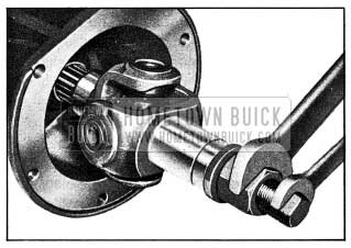
1954 Buick Universal Joint and Torque Ball
The 1954 Buick universal joint is splined to the rear end of transmission main shaft and retained by a heavy steel washer and bolt. It is entirely enclosed by the transmission rear bearing retainer and by the torque ball and retainers which are attached to rear end of the bearing retainer.
The universal joint yokes are provided with hardened and ground steel bushings, held by retainer rings, which provide bearings for the hardened and ground pins of the universal joint cross. The rear yoke is splined internally to engage the propeller shaft, and is ground externally to provide a bearing in a bronze bushing in the torque ball. See figure 4-17.
The torque ball is supported between an inner and outer retainer which are centrally located and bolted to the transmission rear bearing retainer. The retainers are copper plated and the bearing surfaces of the torque ball are also plated to prevent scoring during break-in.
The universal joint, torque ball, and speedometer drive gears are automatically lubricated from the 1954 Buick Synchromesh Transmission. Oil enters the rear bearing retainer through a hole at the top and returns to transmission through a hole at bottom of retainer. A synthetic rubber boot extends from the outer retainer to the flange of torque ball to provide an external oil seal. A breather or air vent is installed in upper side of the rear bearing retainer to prevent a build-up of pressure, due to heat, that would force transmission lubricant out past gaskets and oil seals. See figure 4-17.
4-9 1954 BUICK SYNCHROMESH TRANSMISSION-DESCRIPTION (SERIES 50-60)
The Series 50-60 Synchromesh transmission is larger and of different design than the Series 40 transmission.
The 1954 Buick Synchromesh Transmission is solidly bolted to the rear face of flywheel upper housing, with a heavy paper gasket between, to form a unit assembly with the engine. The transmission main drive gear extends through the clutch driven plate into a single-row-ball pilot bearing seated in the rear end of engine crankshaft. The outer race of main drive gear bearing projects from transmission case to seat in a counterbore in flywheel housing, thus serving as a pilot to center the transmission with engine crankshaft.
1954 Buick Synchromesh Transmission Gears and Shafts
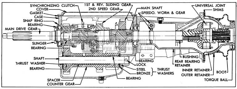
The 1954 Buick Synchromesh Transmission main drive gear is supported by a ball bearing seated in front wall of transmission case. The ball bearing, which is shielded on rearward side, is pressed against a shoulder on main drive gear and held in place by an oil slinger, washer, and retainer (snap ring). The outer race of bearing is grooved for a snap ring which fits between transmission case and flywheel housing to hold bearing and main drive gear in place. See figure 4-19.
1954 Buick Series 50-60 Synchromesh Transmission
The front end of transmission main shaft is piloted in the bored rear end of main drive gear by a bearing consisting of 14 small rollers which are retained in drive gear by a washer and snap ring. The main shaft is also supported by the transmission rear bearing which seats in the rear wall of transmission case. The outer race of rear bearing is grooved for a snap ring which fits between 1954 Buick Synchromesh Transmission case and the rear bearing retainer. The inner race of bearing is retained between a shoulder on main shaft and a snap ring seated in a groove in shaft. A bushing in rear bearing retainer supports the main shaft just forward of the universal joint.
The transmission counter gear is supported by two roller bearings on a shaft which is held stationary in 1954 Buick Synchromesh Transmission case by a grooved pin lock driven into holes in case and rear end of shaft. A tubular spacer and two thrust washers are located around the -shaft between the roller bearings and a retaining washer is located at outer end of each bearing to hold rollers in position. End thrust is taken by a bronze thrust washer at each end of counter gear, with rear washer backed by a steel thrust washer. A hole in hub of gear permits lubricant to reach bearings and thrust washers. See figure 4-19.
The reverse idler gear is provided with two bronze bushings and is supported on a shaft which is held stationary by a grooved pin lock driven into holes in transmission case and front end of shaft. End thrust is taken by a bronze thrust washer at each end of idler gear. A hole in hub of gear permits lubricant to reach bushings and thrust washers.
The second speed gear is provided with a bronze bushing and is mounted on the main shaft in position to mesh with the counter gear. It is held in position between a shoulder on main shaft and a thrust washer retained by a snap ring. The gear is free to rotate on the main shaft except when engaged by the gear synchronizing clutch during second speed operation.
The first and reverse sliding gear is splined to the main shaft, to rear of second speed gear, so that it can be moved forward to engage the counter gear for first speed or rearward to engage reverse idler for reverse. Its forward movement is limited by a snap ring retainer installed in a groove in main shaft. See figure 4-19.
1954 Buick Gear Shift and Synchronization
The gear synchronizing clutch and the first and reverse sliding gear are actuated by the shift mechanism. The gear shift mechanism in the Series 40 and the Series 50-60 transmissions are so similar that they are described together in paragraph 4-10.
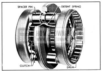
The gear synchronizing clutch is splined to the main shaft to transmit drive when clutch is engaged with either the main drive gear (third speed) or the second speed gear. The clutch assembly includes synchronizing drums and detent springs which act to synchronize the speed of the clutch with the gear it engages during a shift into second or third speed. The drums are joined together by three spacer pins which are notched to engage three detent springs which support the synchronizing parts on the clutch. See figure 4-20.
1954 Buick Gear Synchronizing Clutch-Series 50-60
As the clutch moves toward the gear, the detent springs press the drum into contact with the gear, after which the detent springs compress and disengage notches in the spacer pins to permit the clutch to engage the gear quietly and easily.
Speedometer Gears, Universal Joint and Torque Ball
Although some parts are not interchangeable, the design of the speedometer gears, universal joint and torque ball are the same as in the Series 40 transmission, described in paragraph 4-8 (Subpar. c, d).
4-10 1954 BUICK SYNCHROMESH TRANSMISSION SHIFT CONTROL MECHANISM
The first and reverse sliding gear is moved forward or rearward from the neutral position by a shifter yoke mounted on a shaft supported in left side of transmission case. The second and third speed sliding sleeve (Series 40-50) and the gear synchronizing clutch (Series 70) are similarly actuated by a yoke and shaft on right side of case. Each shifter yoke shaft is notched for engagement by one of two shifter levers mounted on a selector shaft which is supported in 1954 Buick Synchromesh Transmission case at right angle to yoke shaft. The levers are located on selector shaft so that only one lever at a time can engage its yoke shaft. See figures 4-21, 4-22.
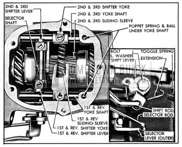
1954 Buick Shift Mechanism in Series 40 Transmission
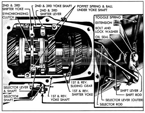
1954 Buick Shift Mechanism in Series 50-60 Transmission
Engagement of a shifter lever with its yoke shaft, to select a gear shift, is obtained by moving selector shaft to right or left as required. This transverse movement of selector shaft is made by a selector lever and shaft which engages a groove in selector shaft on Series 40, and a notch in first and reverse shifter yoke on Series 50-60. The selector lever shaft extends through transmission case and has a lever on its outer end which is actuated by a selector rod connected to the selector control mechanism in steering column.
Forward or rearward movement of the selected shifter yoke shaft, to complete the gear shift, is obtained by rotating the selector shaft. This movement is made by a shift lever mounted on outer left end of shaft and actuated by a shift rod connected to the gear shift control mechanism in steering column. A toggle spring and extension attached to shift lever aids in moving the sliding parts. See figures 4-21, 4-22. A spring loaded poppet ball, housed in a recess in transmission case under each yoke shaft, engages one of three recesses in shaft to hold the shaft in desired position.
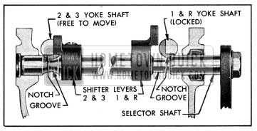
An interlock arrangement permits movement of one shifter yoke and shaft only when the opposite yoke shaft is locked in neutral position. On Series 40, the full diameter of selector shaft engages a notch in one yoke shaft to lock it while the opposite yoke shaft is free to move through a groove in the selector shaft. See figure 4-23.
1954 Buick Transmission Interlock-Series 40
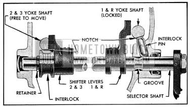
On Series 50-60, the selector shaft pushes an interlock pin up into a notch in the first and reverse shifter yoke shaft to lock it when selector shaft moves to the right. When the selector shaft moves to the left, the interlock pin drops into a groove in selector shaft, thereby unlocking the yoke shaft. A grooved collar mounted on right end of selector shaft and a notch in the second and third shifter yoke shaft provide the locking device for that yoke shaft. See figure 4-24.
1954 Buick Transmission Interlock-Series 50-60
4-11 1954 BUICK SYNCHROMESH TRANSMISSION TROUBLE DIAGNOSIS
Hard Shifting and Block-out
Hard shifting may be caused either by conditions in shift control mechanism in steering column or by conditions in 1954 Buick Synchromesh Transmission assembly. Disconnect shift rod trunnion at control shaft lever to determine which unit is at fault.
Conditions in 1954 Buick Synchromesh Transmission assembly which may cause hard shifting are: (1) If there is excessive resistance at start of shift, shifter yoke shaft poppet spring probably too stiff. (2) Shifter yoke shaft may be bent.
Block-out of second or third gear may be caused by scored synchronizing drums or the cones on gears. In Series 40, rough cam surfaces on ends of sliding sleeve or on synchronizing drums will also cause block-out.
Low and Reverse Gear Clash
Tran mission gears can be made to clash by shifting into low or reverse gear too quickly after clutch pedal is depressed, even though clutch is in perfect working order. This is because inertia of clutch driven plate causes the plate to spin until it is stopped by friction of transmission and transmission lubricant. With warm transmission lubricant and low friction transmission bearings, a reasonable amount of spin is to be expected. The spin does not occur when shifting quickly into second or high gear because the synchronizing unit stops the driven plate.
To eliminate gear clash, sufficient time MUST be allowed before shifting into low after pedal is depressed or else starts must be made in second gear. There is no objection to making starts in second gear on level ground since the clutch slippage under ordinary driving conditions is not sufficient to produce enough heat to damage driven plate facings.
If gear clash continues after allowing proper time for clutch driven plate to stop, check clutch pedal lash and adjust to specified limits. See paragraph 4-4. In exceptional cases of driven plate spinning, clutch pedal lash should be maintained at lf2″. Make sure that idle speed of engine when hot is 450 RPM. A faster idle aggravates driven plate spinning.
Conditions within the 1954 Buick Synchromesh Transmission which may cause gear clash are: (1) Faulty synchronizing drums or cone surfaces; (2) Excessive main shaft end play; (3) On Series 50-60, weak or broken detent springs in gear synchronizing clutch; ( 4) Gear clash also may be caused by a dragging clutch plate.
Noise in Neutral
With car standing, engine running, and 1954 Buick Synchromesh Transmission in neutral, the transmission parts in operation are main drive gear and bearing, counter gear and bearings, reverse idler gear, second speed gear, main shaft pilot bearing. Disengaging clutch will stop movement of all these parts. By disengaging and engaging clutch it can be determined whether noise originates in these transmission parts and whether the noise is normal. Noise in neutral in the form of a constant regular click is usually caused by a nicked gear or bearing.
Gear Noise
Some gear noise is to be expected in all except third speed. Comparison with another car is the only means of determining whether or not gear noise is excessive. Before removing transmission for correction of gear noise determine by test which gears are noisy under load, so that these can be thoroughly inspected when removed.
Gear Rattle During Acceleration
Improperly calibrated clutch driven plate, faulty crankshaft balancer, or scored rear axle gears may cause rattle in 1954 Buick Synchromesh Transmission in third speed, on acceleration. Rattles occurring on wide open throttle between 40 and 60 MPH are usually caused by improper clutch driven plate dampening; a new driven plate should be installed if rattles are objectionable.
Noise When Shifting out of First or Reverse
Shifting out of first or reverse very slowly will usually result in some noise just as the gears disengage. This is normal because of the gear pointing necessary for easy engagement.
Abnormal noise during normally fast shift may be caused by improper clutch release. Check clutch pedal lash and adjust. See paragraph 4-4.
Abnormal noise during normally fast shift, when clutch release is satisfactory, may be caused by damage to pointing on engaging side of teeth on counter gear, reverse idler gear or first and reverse sliding gear. Noise when disengaging both first and reverse, indicates that fault is with sliding gear only. Noise when disengaging reverse only indicates reverse idler gear at fault. Noise when disengaging first speed only indicates counter gear at fault. Tests must be made by disengaging gears while car is still in motion.
Gear Jump-out
In any case of gear jump-out, first check the adjustment of gear shift control mechanism as described in paragraph 4-12. Make certain that poppet balls have full engagement in notches in shifter yoke shaft in all speed p0sitions and neutral. Also make certain that toggle spring extension is not distorted so that it contacts the selector shaft. If these items do not correct gear jump-out, remove transmission for examination of parts.
Gear jumping out of third speed may be caused by misalignment between the flywheel housing and crankshaft. See paragraph 4-14 for alignment correction procedure.
Gear jump-out in any transmission speed position may be caused by loose fit of bearings or bushings involved, weak poppet springs, loose fit of sliding sleeve (Series 40) or synchronizing clutch (Series 50-60) on main shaft, loose fit of sliding gear on sliding sleeve (Series 40) or on main shaft (Series 50-60), worn teeth on mating gears. All items should be carefully inspected.
On Series 50-60, jumping out of second speed may be caused by gear synchronizing clutch being installed with wrong end toward second speed gear. See figure 4-37.
1954 Buick Synchromesh Transmission Lubricant Passing to Rear Axle
Transmission lubricant may pass into rear axle assembly as a result of:
- Scored universal joint or bushing.
- Clearance of more than .006″ between universal joint and bushing in torque ball.
- Worn oil seal in torque tube.
- Loose torque ball adjustment.
- Excessive run-out of front end of propeller shaft.
Scored or Broken Gear Teeth
Gear teeth will be seriously damaged and possibly broken, by failure of car operator to fully engage gears on every shift before engaging clutch and applying engine power.
Considerable damage to gears and bearings will result from running at abnormal speeds in reverse, first and second speed gears. This practice is also detrimental to the engine.
4-12 ADJUSTMENT OF 1954 BUICK TORQUE BALL
Correct adjustment of the torque ball is very important. If torque ball is loose and has end play it will be noisy and will act as a pump to cause leakage of transmission lubricant. If torque ball is too tight, it will cause transmission misalignment, scoring of ball and retainers, and may cause breakage of bolts which attached torque ball to torque tube.
- Disconnect rear axle assembly and move it back out of the way (par. 6-4).
- Mark edge of torque ball outer retainer so that it can be reinstalled in original position, then remove torque ball boot, torque ball, retainers and gaskets from rear bearing retainer.
- Clean and inspect spherical surface of torque ball and both retainers. Inspect torque ball boot and the bushing in torque ball. Inspect seal and gasket at front end of torque tube. Replace parts which are excessively worn, damaged, or scored.
- Prepare two 3/8″ headless guide pins 1 3/8″ long, having 5/8″-16 threads 1/2″ long and screwdriver slots cut in opposite end. Install guide pins in upper bolt holes in rear bearing retainer flange.
- Place one gasket or shim (having 3 notches in outer edge) and the inner retainer on guide pins, with oil drain hole and notch in edge of retainer straight down.
- Lubricate bearing surfaces of torque ball and retainers with transmission lubricant, then install torque ball and outer retainer with shims of proper thickness to fill the space between flanges of inner and outer retainers.
NOTE: Place torque ball with “TOP” mark up and reinstall outer retainer as marked before removal.
- Install all retainer bolts with lock washers, removing guide pins. Do not tighten bolts.
- Prepare a hardwood club for adjusting torque ball as shown in figure 4-25.
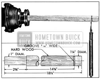
1954 Buick Checking Torque Ball Drag with Club
CAUTION: It is necessary to frequently move torque ball while tightening bolts in order to properly center the ball and retainers. If torque ball binds as bolts are tightened, tap outer retainer lightly at several points, using rawhide or other soft mallet. This will usually relieve the binding condition.
- Attach spring scale to club at groove located 14 3/8″ from end of universal joint and test pull required to move torque ball when all bolts are tight. See figure 4-25. A drag of 15 to 25 pounds should be obtained. If torque ball is too tight or too loose, loosen bolts and repeat the centering and tightening operation, then recheck drag with club and spring scale.
- If torque ball is too tight after repeating the centering and tightening operation remove outer retainer and increase total thickness of shims; if ball is too loose, decrease total thickness of shims. Shims are furnished under Group 5.560 in five thicknesses, and are notched on outer edge for identification as follows:
Thickness – Notches
- .002″-.004″: 4
- .000″-.006″: 3
- .009″-.011″: 2
- .011″-.013″: 1
- .013″-.015″: None
- After changing shims always install torque ball and retainer as specified and use the centering, tightening, and checking procedures specified in steps 9 and 10 above.
Final adjustment must provide a uniform drag of 15 to 25 pounds with scale applied at groove in club.
- Install torque ball boot. Turn the large end back over small end, engage rib in small end in groove on flange of torque ball, then turn large end forward to engage rear end of outer retainer.
- Connect rear axle assembly (par. 6-4).
4-13 REMOVAL AND INSTALLATION OF 1954 BUICK SYNCHROMESH TRANSMISSION
Removal of 1954 Buick Synchromesh Transmission
- Disconnect rear axle assembly and move it back out of the way (par. 6-4).
- Drain transmission lubricant. Fill with clean kerosene and run 1954 Buick Synchromesh Transmission in neutral for about 15 seconds. Drain cleaner.
- Disconnect speedometer cable, shift rod, and selector rod.
On Series 40 only, remove toggle spring and extension, remove shift lever and lock washer from selector shaft and remove outer selector lever, to provide clearance for removing transmission to flywheel housing bolts. Hold shift lever in neutral while removing attaching bolt, to avoid damaging shift lever on shaft inside 1954 Buick Synchromesh Transmission.
- Disconnect rubber thrust pad from transmission support by removing three nuts and plate, then lift out shims located between support and transmission thrust pad. Remove two bolts and plate which attach 1954 Buick Synchromesh Transmission mounting pad to the support.
- Place a suitable jack under rear of engine so that engine will be safely supported while 1954 Buick Synchromesh Transmission is removed.
On car equipped with Air Conditioner, disconnect discharge and suction lines at the compressor in order to avoid damaging the flexible adapters in these lines when raising or lowering the engine.
- Raise engine and transmission just enough to relieve the load on transmission support, then remove the support from frame, noting location and number of shims present. Remove thrust pad from thrust plate.
- Remove the two top transmission to flywheel housing bolts and install Guide Pins J 851 to support 1954 Buick Synchromesh Transmission. See figure 4-26.
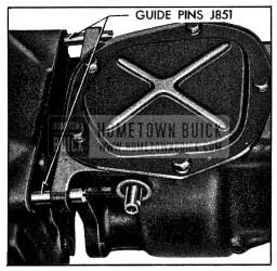
1954 Buick Transmission Guide Pins J 851
Remove lower bolts, then move transmission straight back and lower to floor. CAUTION: If guide pins are not used and weight of transmission is allowed to rest on main drive gear in clutch driven plate hub, the driven plate will be damaged.
Installation of 1954 Buick Synchromesh Transmission
- Lightly coat the splines on end of main drive gear with Lubriplate for a distance of not more than 1″. Do not apply an excess that will push off at driven plate hub and get on driven plate facings.
- Make certain that front face of transmission case and face of flywheel housing are absolutely clean. Install Guide Pins J 851 in upper bolt holes in housing (fig. 4-26) and install a new 1954 Buick Synchromesh Transmission gasket. Make certain that spring washer is in place behind clutch release bearing support in housing.
- Lift 1954 Buick Synchromesh Transmission into place and fully support it until the main drive gear bearing enters flywheel housing. Clutch driven plate will be damaged if guide pins are not used and weight of transmission is allowed to rest on main drive gear in driven plate hub.
- Install lower transmission attaching bolts, then the upper bolts, and tighten all bolts evenly and securely. CAUTION: If a gap exists between transmission case and flywheel housing do not tighten bolts as case may be broken. Remove transmission and check position of main drive gear bearing snap ring, which may have slipped out of place during installation.
- Install rubber thrust pad on thrust plate attached to bearing retainer. Install 1954 Buick Synchromesh Transmission support with original shims, which should be of proper number and thickness to just fill space between support and frame.
- Lower the 1954 Buick Synchromesh Transmission to rest on the support and attach the mounting pad to the support with bolt plate and self-locking nuts.
- With engine and transmission resting freely and normally on mountings, install sufficient shims between the thrust pad and transmission support to fill the existing space. Insert shims from above, then install the bolt plate and three nuts which attach thrust pad to support. See figure 2-41.
- Connect speedometer cable.
On Series 40, install outer selector lever, shift lever, toggle spring and extension. Hold shift lever in neutral while installing and tightening attaching bolt and lock washer to avoid damaging shifter levers on selector shaft. Install toggle spring and extension so that extension passes underneath selector shaft. - Connect lower shift rod and selector rod to their levers.
- Place 7/8 pint of transmission lubricant in Series 40 or 1 1/4 pints of lubricant in Series 50-60 transmission. In addition, inject 1/2 pint of transmission lubricant through universal joint yoke. See paragraph 1-1 for specified lubricant.
- Install rear axle assembly as described in paragraph 6-4.
- Road test car and check 1954 Buick Synchromesh Transmission for:
- Proper shifting into all speeds.
- Correct synchronization when shifting into second and third speed.
- First and second speed slip-out, on drive and coast.
- Gear, bearing, or shifter yoke noises in all speeds and neutral.
- Rattles in shift control mechanism.
4-14 ALIGNMENT OF 1954 BUICK SYNCHROMESH FLYWHEEL UPPER HOUSING
The flywheel upper housing which joins the1954 Buick Synchromesh Transmission to the engine crankcase is attached to the crankcase by bolts, with two straight dowels to maintain alignment.
Misalignment between the pilot hole which receives the main drive gear bearing in rear wall of housing and the pilot bearing in rear end of crankshaft may cause the 1954 Buick Synchromesh Transmission to be noisy or to slip out of high gear. To insure correct alignment in production, the pilot hole is bored in the housing after it is assembled to the cylinder crankcase. The flywheel housing furnished for service is completely machined, but it must be checked for alignment after installation.
If an existing housing is suspected of being out of alignment it may be checked after removal of the transmission and clutch assemblies. If a new housing or cylinder crankcase is being installed, alignment should be checked before the flywheel, clutch and transmission are installed. When checking alignment the engine must be in an upright position, dowel pins must be installed, and all housing bolts must be tight.
Checking Alignment of Flywheel Upper Housing
- Remove 1954 Buick Synchromesh Transmission (par. 4-11) and clutch (par. 4-5), leaving flywheel in place.
- Attach Indicator Support J 4710-1 to flywheel with two flywheel bolts. Mount Dial Indicator KMO 30-B and Hole Attachment KMO 30-F on pilot with Sleeve KMO 30-K. Adjust ball end of hole attachment to bear against side of pilot hole in flywheel housing. See figure 4-27.
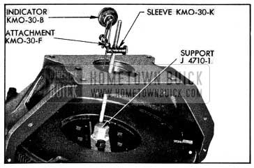
1954 Buick Checking Alignment of Housing at Pilot Hole
Correction of Flywheel Upper Housing Misalignment
- Remove flywheel upper housing and dowel pins from crankcase.
- Drill out bolt holes in flywheel housing with a 1/2″ drill.
- Install flywheel housing without dowel pins, and leave bolts just loose enough to permit shifting of housing by tapping with lead hammer.
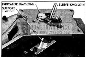
- Install dial indicator as shown in figure 4-27, and check run-out at pilot hole in housing.
- Shift housing by tapping with lead hammer as required to bring run-out at pilot hole within .002″ indicator reading. Tighten housing bolts and re-check run-out.
- Using Special Reamer J 2548-3 and Ratchet Wrench J 808-6, ream the dowel holes and install two oversize dowel pins J 808-5.
- Mount dial indicator to bear against rear face of flywheel housing at a radius of 2%”, as shown in figure 4-28.
1954 Buick Checking Run-Out of Rear Face of Housing
4-15 DISASSEMBLY, INSPECTION, ASSEMBLY OF 1954 BUICK SYNCHROMESH TRANSMISSION (SERIES 40)
Disassembly of 1954 Buick Synchromesh Transmission
- Thoroughly clean all dirt from exterior of transmission to avoid getting dirt into bearings when 1954 Buick Synchromesh Transmission is opened. Remove 1954 Buick Synchromesh Transmission cover and gasket.
- Lock 1954 Buick Synchromesh Transmission in third speed to prevent sliding sleeve and sliding gear from dropping, then remove transmission rear bearing retainer, with second speed gear, main shaft, universal joint and torque ball as an assembly.
- Remove the four set screws from shifter levers and shifter yokes, using Remover J 2895. See figure 4-29.
1954 Buick Removing Set Screw with Remover J 2895
NOTE: If poppet balls and springs are not to be replaced the shafts may be pushed to rear of case far enough to release the yokes while holding poppet balls in place.
- Remove sliding gear and the sliding sleeve, then remove the selector lever and shaft with spring washer, flat washer, and oil seal from transmission case.
- Remove the counter gear shaft and lock ball by driving shaft out through rear end of transmission case, using Bearing Loader J 1334 and a Babbitt hammer. Make sure that bearing loader follows the shaft closely so that counter gear bearings and thrust washers will be held in place. Allow counter gear to rest on bottom of case.
- Remove the snap ring from main drive gear bearing and tap drive gear and bearing assembly toward rear of transmission case to remove it.
- Carefully raise counter gear out of case so that bearing loader and counter gear bearings will not fall out. Remove all thrust washers.
- Drive reverse idler gear shaft lock into the shaft, then remove shaft, idler gear, and thrust washer.
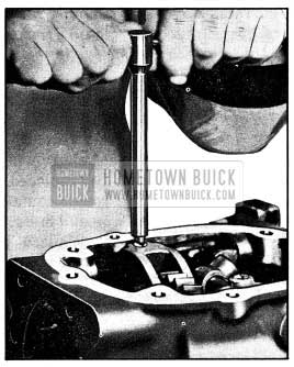
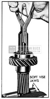
- Disassemble main drive gear if any parts are to be replaced. Remove synchronizing drum by prying retainer over shoulder on gear, leaving retainer in drum. Remove oil seal, retainer (snap ring), washer, and oil slinger from drive gear, then remove bearing by jarring shaft on block of wood .or lead. See figure 4-30. Remove main shaft pilot roller bearing by removing retainer (snap ring) and retainer washer.
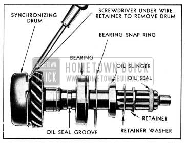
1954 Buick Disassembly of Main Drive Gear
NOTE: If work to be done requires disassembly of rear bearing retainer, proceed with the following steps.
- Mount rear bearing retainer securely in a vise.
- Remove second speed synchronizing drum by prying retainer over shoulder on second speed gear, leaving retainer in drum. Remove snap ring from main shaft then remove thrust washer and second speed gear from main shaft.
- Remove speedometer driven gear.
- Mark edge of torque ball outer retainer so that it can be reinstalled in original position, then remove torque ball boot, torque ball, retainers and gaskets.
- Remove retaining bolt and washer then pull universal joint from main shaft, using Puller J682-A. To use the puller, install the pressure plug in transmission main shaft, insert puller body in universal joint rear yoke and install “C” washer in groove in puller body on front side of yoke, then turn screw handle clockwise. See figure 4-31.
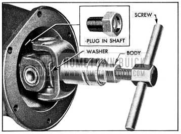
1954 Buick Removing Universal Joint with Puller J 682-A
Cleaning and Inspection of 1954 Buick Synchromesh Transmission Parts
Clean and inspect all ball and roller bearings as described under Bearing Service (par. 1-10). Thoroughly clean all other parts except rubber mountings in CLEAN solvent and wipe dry with CLEAN cloths. Inspect parts as follows:
- Gears and Shafts. Carefully inspect teeth and other ground surfaces of all gears for wear, scoring, pitting, chips, nicks, and burrs.
Do not confuse manufacturing cutter marks with scores or pits. Conical surfaces of gears where contacted by synchronizing drums must be smooth and free of burrs. Slight scores or burrs may be honed off with a fine stone, however, if any gear is chipped or excessively worn it should be replaced.
Inspect all shafts for wear roughness on bearing surfaces. Check fit of gears on shafts upon which they are mounted. The sliding sleeve must slide freely on splined section of main shaft, but without appreciable backlash. - Synchronizing Drums. The cam surfaces of synchronizing drums must be smooth. The conical surfaces of synchronizing drums must be free of burrs or scores, and oil grooves must be clean. Never polish this surface or change the angle.
- Selector Shaft, Shifter Yokes and Shafts, Toggle Spring Extension. Check selector shaft and shifter yoke shafts on a flat surface to see whether they are bent. A bent shaft will cause hard shifting, and should be replaced. If a shifter yoke is bent or has rough contact surfaces it will cause hard shifting and noise, therefore, it should be replaced. Replace poppet springs if distorted or of doubtful strength.
Check toggle spring extension to make sure it is not distorted. An improperly shaped extension will bear against the selector shaft and actually tend to pull 1954 Buick Synchromesh Transmission out of second speed. Figure 4-32 shows the correct shape for extension. A bent extension should be reshaped to dimension shown, or replaced.
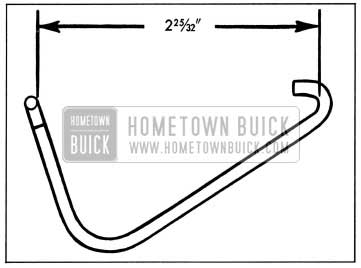
1954 Buick Toggle Spring Extension
Assembly of 1954 Buick Synchromesh Transmission
Assemble the 1954 Buick Synchromesh Transmission by reversing the sequence of steps given for disassembly. In addition, observe the following instructions that apply to assembly.
- Condition of Parts. Make certain that all parts are absolutely clean and that gears and synchronizing drums are free of nicks or burrs. Use all new gaskets and oil seals or packings to insure against leakage of lubricants. Use all new snap rings, and retainers of snap ring type. Snap rings, are frequently distorted during removal and are difficult to true up satisfactorily for further service.
- Observe instructions given under Bearing Service (1-9) on proper installation of ball bearings. Coat bearings with clean transmission lubricant at time of installation, to insure initial lubrication.
- Universal Joint. Use Replacer J 865 to install universal joint on main shaft. See figure 4-33.
1954 Buick Installing Universal Joint with Replacer
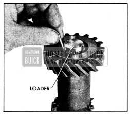
1954 Buick Installing Counter Gear Bearings with Leader
Pack bearing rollers in white vaseline to hold them in place and make certain that all rollers are installed (25 in each bearing). Leave loader in gear until it is pushed out by the counter gear shaft during installation.
Install locking ball counter gear shaft then install shaft through rear end of case, driving rear end of shaft slightly below face of case so that rear bearing retainer may be tightened against its gasket.
- First and Reverse Sliding Gear. Install the first and reverse sliding gear so that “U” groove in one face of gear is toward front of 1954 Buick Synchromesh Transmission.
- Selector Lever and Shaft, Washers and Oil Seal. Place spring washer, fiat washer, and oil seal on shaft in the order named, with crowned side of spring washer against the flat washer. Apply Lubriplate to shaft before installation of assembled parts in transmission case.
- Selector Shift and Shifter Levers. Coat oil seal with Lubriplate and install selector shaft through left side of transmission case to avoid damaging the oil seal. The long shifter lever goes on left side of case, and short shifter lever goes on right side. Install a new welsh plug in right side of case, sealing it with white lead or other compound. A welsh plug must also be installed in front side of case to seal opening for second and third shifter yoke shaft. Make certain that selector shaft slides freely after installation, otherwise hard selection of proper gear will result at control lever.
- Shift Lever, Toggle Spring and Extension. Hold shift lever in neutral position while installing and tightening attaching bolt and lock washer, to avoid damaging shifter levers on selector shaft. Install toggle spring and extension so that the extension passes underneath the selector shaft. Make sure that extension is not distorted so that it bears against the selector shaft.
4-16 DISASSEMBLY, INSPECTION, ASSEMBLY OF 1954 BUICK SYNCHROMESH TRANSMISSION (SERIES 50-60)
Disassembly of 1954 Buick Synchromesh Transmission
- Thoroughly clean all dirt from exterior of transmission to avoid getting dirt into bearings when 1954 Buick Synchromesh Transmission is opened.
- Remove 1954 Buick Synchromesh Transmission cover and gasket, toggle spring, and spring extension.
- Remove speedometer driven gear.
- Mark edge of torque outer retainer so that is can be reinstalled in original position then remove torque ball boot, torque ball, retainers and gaskets.
- Remove retaining bolt and washer, then pull universal joint from main shaft, using Puller J 682-A. To use puller, install the pressure plug in transmission main shaft, insert puller body in universal joint rear yoke and install “C” washer in groove in puller body on front side of yoke, then turn screw handle clockwise. See figure 4-31.
- Remove universal joint retaining ring from main shaft, then remove rear bearing retainer and gasket from 1954 Buick Synchromesh Transmission case.
- Remove speedometer worm gear, stop ring, and rear bearing snap ring from main shaft.
- Move main shaft back until rear bearing is clear of case. Remove snap ring from bearing and pull bearing from shaft.
- Remove shifter yoke set screws, using Remover J 2895 (shown in fig. 4-29), then lift the main shaft and assembled parts out through top of transmission case. See figure 4-35.
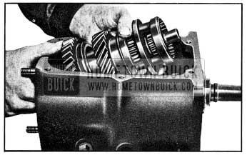
1954 Buick Removing Main Shaft Assembly
1954 Buick Removing Snap Ring from Main Shaft
Cleaning, Inspection, Assembly of 1954 Buick Synchromesh Transmission
Clean and inspect 1954 Buick Synchromesh Transmission parts as prescribed for Series 40 transmission in paragraph 4-15 (b).
Assemble the 1954 Buick Synchromesh Transmission by reversing the sequence of steps given for disassembly. In addition, observe the following instructions that apply to assembly.
- Use instructions prescribed for Series 40 in paragraph 4-15 (c), where applicable.
- Drive the reverse idler gear shaft lock 1″ below surface of boss in case.
- Use Universal Joint Replacer J 855 and Counter Gear Bearing Loader J 1001.
- When installing counter gear, place the steel thrust washer between the rear bronze thrust washer and boss in case. Drive counter gear shaft lock flush with surface of case.
- Install the small wire spacer ring, Part No. 1309249, in groove in main shaft before installing snap ring which retains the second speed gear thrust washer. This spacer centers the snap ring so that it projects equally all around the shaft.
The synchronizing clutch must be installed with the counterbored end toward the second speed gear to insure full engagement of clutch with gear and avoid slipping out of second speed. The second speed end of clutch is stamped with a letter “S.” Gear synchronizing clutches furnished for service have a figure “7” (to indicate 7° angle) stamped on the second speed drum. Do not use replacement clutch having any other number stamped on drum. See figure 4-37.
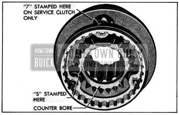
1954 Buick Counterbore and Marks on Second Speed End of Clutch
Leave A Comment
You must be logged in to post a comment.