GROUP 4 – 1954 BUICK CLUTCH, S-M TRANSMISSION, UNIVERSAL JOINT
4-1 1954 BUICK CLUTCH SPECIFICATIONS
Tightening Specifications
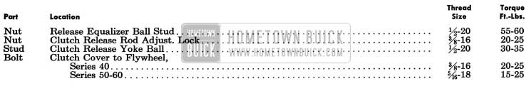
1954 Buick Clutch Tightening Specifications
1954 Buick Clutch Specifications
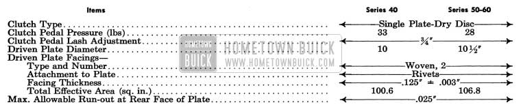
1954 Buick Clutch Specifications
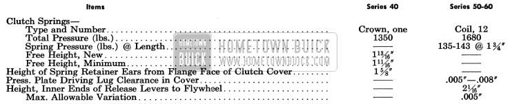
1954 Buick Clutch Specification
4-2 DESCRIPTION OF 1954 BUICK CLUTCH
Single plate, dry disc clutches of two different designs are used in cars equipped with synchromesh transmissions. The 1954 Buick Series 40 clutch is distinguished by a “crown” type clutch spring which serves the same purpose as conventional release levers and drive lugs, in addition to providing pressure for clutch engagement. The Series 50-60 clutch is of conventional design with coil type clutch springs and adjustable release levers.
1954 Buick Series 40 Clutch Assembly
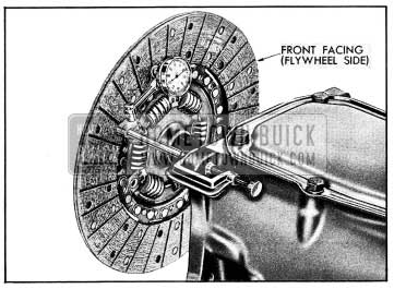
The “crown” type clutch spring is a spring steel disc formed in waves to provide spring action and is cone-shaped when in the free position. Notches in the inner edge of the clutch cover fit over the waves a short distance from the outer edge of clutch spring to transmit drive to the 1954 Buick clutch spring. Twelve lugs cast on the pressure plate engage waves at the outer edge of clutch spring to take the pressure as well as drive from the spring. The pressure plate and clutch spring are attached to the clutch cooler by six spring retainers which hook over ears on inner edge of cover, pass around outer edge of clutch spring and through holes in lugs on pressure plate. See figure 4-1.
1954 Buick Clutch and Flywheel Assembly-Series 40
When the 1954 Buick clutch is in the engaged position, the clutch cover compresses the clutch spring, causing it to exert heavy pressure against the pressure plate. The pressure plate clamps the driven plate against the flywheel with sufficient force to transmit the power of the engine without slippage. The power drive is from flywheel to clutch cover, cover to clutch spring, spring to pressure plate, and from pressure plate and flywheel to driven plate. See figure 4-1.
When the 1954 Buick clutch is disengaged, the clutch release bearing presses forward against the high inner edge of clutch spring, which flattens the spring. The curved inner ends of the spring retainers act as fulcrum points which cause the spring to relieve pressure against pressure plate. The pressure plate is then pulled away from driven plate by the spring retainers.
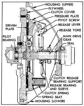
Series 50-60 Clutch Assembly
The clutch cover is bolted to the flywheel and three lugs on the pressure plate engage slots in the cover to transmit drive to the plate. Twelve equally spaced clutch springs are located between the cover and pressure plate. Three clutch release levers are pinned at their outer ends to the pressure plate and to pivot screws attached to the clutch cover. The inner ends of the release levers are in position to be engaged by the clutch release bearing. See figure 4-2.
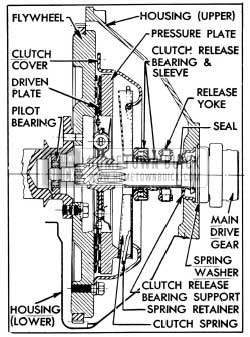
1954 Buick Clutch and Flywheel Assembly-Series 50-60
When the 1954 Buick clutch is in the engaged position, the release levers are clear of the release bearing and the clutch springs cause the pressure plate to clamp the driven plate against the flywheel with sufficient force to transmit power of the engine without slippage. The power drive is from flywheel to clutch cover, cover to pressure plate, and from pressure plate and flywheel to driven plate.
When the 1954 Buick clutch is disengaged, the 1954 Buick clutch release bearing presses forward on the inner ends of the release levers which pivot at the pivot screws and force the pressure plate rearward against the pressure of clutch springs. The pressure plate is moved rearward far enough to free the driven plate. See figure 4-2.
1954 Buick Clutch Driven Plate
The 1954 Buick clutch driven plate assembly is mounted with a free sliding fit on the transmission main drive gear and is keyed to the gear by ten splines. The front end of the main drive gear is piloted by a ball bearing pressed into a recess in rear end of engine crankshaft. See figures 4-1, 4-2.
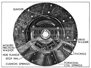
The outer area of the driven plate is divided into segments which are formed in low waves to provide springs between the plate facings and thereby cushion engagement of the 1954 Buick clutch. A woven facing, grooved to give quick release, is riveted to each side of every segment of plate. When the 1954 Buick clutch is fully released, the waved segments cause the facings to spread approximately .050″ and the movement of pressure plate provides approximately .030″ clearance to assure full release of driven plate. See figure 4-3.
1954 Buick Driven Plate, Transmission Side-Series 40
The driven plate assembly is designed to prevent torsional periods of the engine from being transmitted to the transmission gears and causing rattle. This is accomplished by driving the plate hub through torsional coil springs and providing frictional dampening by means of molded friction washers. The coil springs are covered on transmission side of plate by a slinger which keeps oil or oil vapor from the driven plate facings.
1954 Buick Clutch Release Mechanism
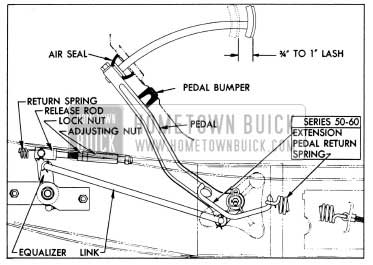
The 1954 Buick clutch pedal is supported on the car frame upon the same shaft and bracket which supports the brake pedal. The pedal is bushed and is lubricated through a passage in the shaft which has a lubrication fitting.
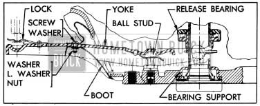
The 1954 Buick clutch pedal is connected by a nonadjustable link to the outer arm of a release equalizer which permits smooth engagement of clutch without being affected by movement of the engine on its mountings. The inner end of equalizer is fitted with a rubber bushing which rotates on the pin of a bracket attached to engine. The outer end of equalizer rotates on a ball stud attached to car frame. A spring and two spring seats inside equalizer maintain pressure on the split bearings which support equalizer on stud ball. A lubrication fitting is installed on equalizer and seals in close both ends to exclude dirt and water. See figure 4-4.
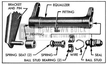
1954 Buick Clutch Release Equalizer-Disassembled
The inner arm of clutch release equalizer is connected by an adjustable rod to the outer end of the release yoke which is pivoted on a ball stud located in the flywheel housing. The yoke is held on the ball stud by a U-shaped spring riveted to yoke. A boot around the yoke provides a flexible closure for the yoke opening in flywheel housing. The inner end of release yoke is in position to push forward on the clutch release bearing sleeve when 1954 Buick clutch pedal is depressed. A U-shaped spring riveted to release bearing sleeve holds bearing sleeve in contact with yoke.
The 1954 Buick clutch release bearing and sleeve assembly is mounted upon a bearing support which encircles the transmission main drive gear. The bearing is filled with lifetime lubricant in production and no further lubrication is required. The bearing support is flared at the rear end to seat in flywheel housing and is held in place by a spring washer and the outer race of transmission main drive gear bearing. See figures 4-1, 4-2.
A coiled return spring is connected between the 1954 Buick clutch release rod clevis pin and the frame to keep the clutch release bearing out of contact with the clutch spring when clutch is engaged.
On Series 50-60 only, an over-center type actuating spring holds the pedal firmly against a rubber bumper on the toe board when clutch is in engaged position, and helps to reduce pedal pressure as it goes over center when 1954 Buick clutch is disengaged. The actuating spring is attached to the frame by an eye bolt and to a pin on clutch pedal by an extension which straddles the pivot point of pedal. The spring and extension are positioned so that the pedal is pulled upward in the free position and pulled downward when depressed to disengage the 1954 Buick clutch. See figure 4-5.
1954 Buick Clutch Pedal Lash Adjustment
4-3 1954 BUICK CLUTCH TROUBLE DIAGNOSIS
Excessive Pedal Pressure
The pressure required to depress 1954 Buick clutch pedal to toe board should not exceed 35 pounds on Series 40 or 28 pounds on Series 50-60. If pedal pressure is excessive, make certain that pedal is not binding in floor mat or the seal on underside of toeboard. Thoroughly lubricate clutch pedal and release equalizer with chassis lubricant. NOTE: Excessive pedal pressure may be caused by using excessive grease gun pressure on equalizer, which may force the rubber inner bearing out into contact with equalizer bracket on engine.
If excessive pedal pressure still exists after release linkage is properly lubricated, lubricate internal working parts of 1954 Buick clutch as described in paragraph 4-4.
1954 Buick Clutch Noise
Squeaking and grinding noises during 1954 Buick clutch pedal operation are usually caused by heavy friction in the release linkage or internal parts of clutch assembly. Before condemning the release bearing, thoroughly lubricate clutch pedal and release equalizer and, if necessary, lubricate internal working parts of clutch as described in paragraph 4-4.
1954 Buick Clutch Grab or Chatter
A very slight amount of oil on driven plate facings will cause 1954 Buick clutch grab and chatter. A new driven plate must be installed if original plate facings contain oil since removal of oil from facings is not practical.
When oil is found on facings, examine pilot bearing, transmission drain back, rear engine bearing, and oil leaks which might drain back into clutch housing between upper and lower flywheel housings.
On Series 50-60, improper adjustment of release levers will cause clutch chatter. To correct this condition remove 1954 Buick clutch assembly and adjust levers (par. 4-6, e).
1954 Buick Clutch Drag or Failure to Release
To test for clutch drag or failure to release, depress clutch pedal to toeboard with engine running and shift transmission into low gear. Hold pedal depressed and shift transmission to neutral, wait about 15 seconds with pedal depressed and again shift into low gear. If 1954 Buick clutch is not releasing completely a gear clash will occur.
If test shows that 1954 Buick clutch is releasing properly and complaint is of gear clash going into low and reverse gears, refer to paragraph 4-1 b.
If test shows that clutch is not releasing properly, check clutch pedal lash (par 4-4) and check release linkage for lost motion. Correct as necessary and again test for clutch drag.
On Series 40, if clutch drag cannot be corrected in release linkage, remove flywheel lower housing and check for proper contact between 1954 Buick clutch spring and cover as described in paragraph 4-5 (b, step 9). If removal of clutch is found necessary, check driven plate for oil soaked or cracked facings, also for run-out and for free movement on main drive gear (par. 4-6, b).
On Series 50-60, if clutch drag cannot be corrected in release linkage remove 1954 Buick clutch and check adjustments of release levers. Check driven plate for oil soaked or cracked facings, also for run-out and for free movement on main drive gear (par. 4-6, b).
1954 Buick Clutch Slipping
First make certain that 1954 Buick clutch pedal is adjusted for specified lash (fig. 4-5) and that pedal is not binding. One type of clutch slippage is sometimes wrongly diagnosed as due to a weak clutch spring. This slippage occurs during gear shifting and full engagement of the clutch is not obtainable until the engine speed is reduced. After full engagement is obtained no further slippage occurs during acceleration or under full load. This condition is usually due to the clutch driven plate hub sticking on the splines of the transmission main drive gear. Correction can be made by removing the 1954 Buick clutch and thoroughly cleaning splines of driven plate and main drive gear then applying a light coating of Lubriplate. On Series 50-60 , make sure that release lever pins are not binding, and that pressure plate driving lugs are not binding in clutch cover.
If 1954 Buick clutch springs are suspected of being weak, inspect them as described in paragraph 4-6 (b).
4-4 1954 BUICK CLUTCH ADJUSTMENT AND LUBRICATION
1954 Buick Clutch Pedal Lash Adjustment
It is very important to maintain proper clutch pedal lash at all times. Insufficient pedal lash will cause pressure of release bearing against the clutch spring, resulting in abnormal wear of these parts; it may also cause clutch slippage and abnormal wear of driven plate if pressure is great enough to prevent positive engagement of 1954 Buick clutch.
- Make certain that the return spring pulls clutch pedal firmly against pedal bumper on toeboard when pedal is released. If pedal does not contact pedal bumper check pedal and linkage for binding or lack of lubrication. Check condition of return spring, and on Series 50-60, check condition of actuating spring and make sure that spring eye bolt is fully tightened. See figure 4-5.
- Check pedal free movement or lash by pushing on pedal pad until release bearing contacts clutch spring. Do not mistake tension of pedal return spring as an indication of lack of pedal lash. Free movement or lash of clutch pedal should be 3/4″to 1″, measured at pedal pad.
- If adjustment is necessary, loosen lock nut and turn adjusting nut on clutch release rod as required to secure 3/4″ lash, then tighten lock nut securely. See figure 4-5.
Lubrication of 1954 Buick Clutch Internal Parts
Lubrication of 1954 Buick clutch pedal and release equalizer is included in Lubricare every 1000 miles (par 1-1). Lubrication of clutch internal working parts is usually required only at time clutch is assembled and installed; however, if lubrication becomes necessary to eliminate squeaks or excessive pedal pressure, proceed as follows:
- Remove flywheel lower housing.
- Disconnect rod from clutch release yoke, unhook boot from opening in flywheel upper housing, and pull yoke outward to disengage it from ball stud. See figure 4-6.
1954 Buick Clutch Release Yoke and Boot
On Series 50-60, brush lubricant on pressure plate driving lugs where they contact cover. Work clutch pedal a number of times to work lubricant into contact points.
Rotate flywheel until each release lever in turn is in lowest position, then very sparingly oil the release lever pins and sides of release levers. Allow time for any surplus oil to drain off before turning flywheel, to avoid getting oil on driven plate facings. Release lever pins also may be lubricated by spraying with powdered graphite, which will not damage driven plate facings. This may not afford immediate relief but if 1954 Buick clutch is operated while engine is running, after installation of flywheel lower housing, the graphite will work into the bearing surfaces.
- Install flywheel lower housing.
4-5 REMOVAL AND INSTALLATION OF 1954 BUICK CLUTCH
Removal of 1954 Buick Clutch
- Remove rear axle assembly (par. 5-4) and transmission (par. 4-14). Remove flywheel lower housing.
- Disconnect release rod from release yoke and remove yoke boot and release rod nut lock which are bolted to yoke. See figure 4-6.
- Remove spring washer which retains release bearing support in flywheel housing and remove support and gasket.
- Pull outward on release yoke to free it from the ball stud in flywheel housing and remove yoke and release bearing through bottom of housing. Separate yoke from bearing.
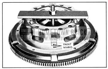
- Mark the clutch cover and the flywheel with a center punch so that cover can be reinstalled in the same position on flywheel in order to preserve engine balance.
- Loosen each clutch cover bolt a little at a time in order to relieve clutch spring pressure evenly and avoid distortion of cover.
On Series 50-60, metal spacers placed between release levers and inner edge of clutch cover will aid removal and later disassembly by holding clutch springs compressed.
- Support pressure plate and cover assembly while removing the last bolts, then remove the assembly and driven plate.
Installation of 1954 Buick Clutch
- Very sparingly apply front wheel bearing lubricant to main drive gear pilot bearing in crankshaft. If too much lubricant is used it will run out on face of flywheel when hot and ruin driven plate facings. Make sure that surface of flywheel is clean and dry.
- Make sure that splines in driven plate hub are clean and apply a light coating of Lubriplate. Driven plate facings must be clean and dry.
- Place driven plate on pressure plate with oil slinger toward pressure plate, then place clutch assembly in position against flywheel, being sure to align marks made on flywheel and cover before removal. Install cover bolts with lockwashers but do not tighten bolts.
- Insert a spare main drive gear through hub of driven plate and into the pilot bearing. Tighten each clutch cover bolt several turns at a time to draw cover evenly into pilot of flywheel and avoid distortion of cover. While tightening cover bolts, move main drive gear from side to side to center driven plate with pilot bearing. If plate is not properly centered it will be difficult to slide transmission into place. Make sure all cover bolts are uniformly tightened.
On Series 50-60, remove spacers from between cover and release levers.
- Fill groove in release bearing sleeve with wheel bearing lubricant. Coat release yoke ball stud and ball recess in release yoke with Lubriplate or Delco Brake Lubricant. Attach release bearing to release yoke and attach yoke to ball stud in flywheel housing.
NOTE: Series 40 release bearing has rounded surface for contact with clutch spring. This surface is flat on Series 50-60 bearing.
- Install release bearing support with a new gasket, placing support in flywheel housing with the tab on support aligned with molded recess in housing to permit positive drain back of oil to transmission. Install spring washer with outer edge against bearing support.
- Install transmission (par. 4-14), being sure to use Guide Pins J 851 to avoid damage to clutch driven plate which would result if weight of transmission is allowed to rest on main drive gear in driven plate hub.
- Install boot and release rod nut lock on yoke (fig. 4-6), attach release rod to yoke, then adjust for clutch pedal lash of 3/4″ (par. 4-4).
- On Series 40, have a helper hold clutch fully disengaged, then check with a feeler gauge for space between cover and clutch spring at points of contact. See figure 4-7.
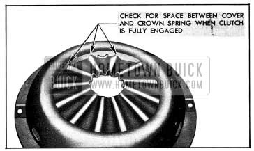
1954 Buick Points to Check Contact of Clutch Spring with Cover
The 1954 Buick clutch will not fully disengage if any one of the clutch spring contact points fails to solidly contact the cover. This condition must be corrected by removing clutch and properly setting the spring retainer ears on cover. See figure, 4-9.
4-6 DISASSEMBLY, INSPECTION, ASSEMBLY OF 1954 BUICK CLUTCH
Disassembly of 1954 Buick Series 40 Clutch
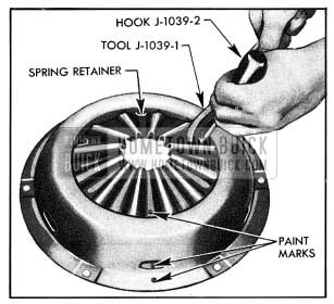
- Place pressure plate and cover assembly on flat work surface and mark cover, pressure plate, and 1954 Buick clutch spring with paint so that parts can be reassembled in the same relationship to each other in order to preserve engine balance. See figure 4-14.
1954 Buick Attaching Spring Retainer to Cover
1954 Buick Assembling Pressure Plate, Clutch Spring and Retainers
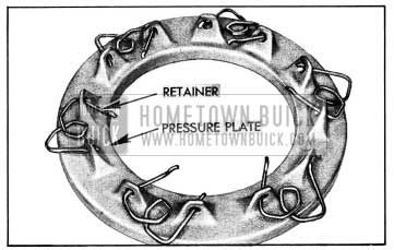
1954 Buick Positioning Spring Retainers
Disassembly of Series 50-60 Clutch
- Mark clutch cover and one driving lug of pressure plate with paint so that parts can be re-assembled in the same relationship to each other in order to preserve engine balance. See figure 4-8.
1954 Buick Clutch Disassembly-Series 50-60
Inspection of 1954 Buick Clutch Parts
Wash all metal parts of 1954 Buick clutch, except release bearing and driven plate, in suitable cleaning solution to remove dirt and grease. Soaking release bearing in cleaning solution may permit solution to seep into bearing and destroy the lubricant. Soaking driven plate in cleaning solution may damage the facings.
- Flywheel and Pressure Plate. Examine friction surfaces of flywheel and pressure plate for scoring or roughness. Slight roughness may be smoothed with fine emery cloth, but if surface is deeply scored or grooved the part should be replaced.
- Clutch Cover, Series 40. Inspect clutch cover for cracks or distortion. Place cover on a flat surface and measure setting of each of the six ears where spring retainers are attached. The dimension from flange surface of cover to top surface of each ear should be 1 5/8 inch. See figure 4-9. If dimension is not 1 5/8 inch, and cover is otherwise serviceable, the ears should be bent as required, using care to avoid cracking the metal.
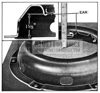
1954 Buick Setting of Spring Retainer Ears on Clutch Cover
Clutch Cover, Series 50-60. Inspect clutch cover for cracks or distortion. Place pressure plate in cover and check clearance between driving lugs and edges of slots in cover, using feeler gauges. The clearance should be .005″ to .008″; excessive clearance may cause rattle when engine is intermittently accelerated with clutch disengaged.
- Clutch Spring-Series 40. Inspect clutch spring for cracks, particularly at inner edge. Cracks weaken the spring and make replacement necessary.
It is a normal condition to have some wear at the inner edge of spring, resulting from release bearing sliding radially on clutch spring. Due to variation in diameters of holes, the contact of bearing race may be at varying distances from edge of hole in different springs. If hole is of small diameter, release bearing forms depression having centers approximately 3/16″ from edge of hole. This type of wear does not affect the operation or efficiency of the clutch spring; the spring should not be discarded unless the depression is worn deep enough to cut through the metal. If hole is of large diameter, bearing will be at edge of hole resulting in thin metal. Unless the metal is worn to a sharp knife edge, the spring will operate satisfactorily and should not be discarded.
The Series 40 clutch spring will flatten slightly due to the metal taking a permanent set, which is characteristic of any type of spring after continued flexing. The normal height of a new spring is 1 13/16”. See figure 4-10.
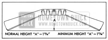
1954 Buick Clutch Spring, Cross Section-Series 40
After only a short period of usage this height will be reduced somewhat; however, if height is not less than 1 11/16″ the spring will still retain sufficient pressure to prevent clutch slippage and will operate satisfactorily providing, of course, that spring is not cracked. NOTE: Testing a clutch spring by standing on it and jumping up and down, forcing spring through does not necessarily indicate spring should be replaced.
1954 Buick Clutch Springs-Series 50-70. Inspect springs for cracks or distortion. If test equipment is available, test springs for strength. The 12 springs should each have a pressure of 135- 143 pounds when compressed to 1 3/4″ length.
- Clutch Driven Plate. Inspect driven plate for condition of facings, loose rivets, broken or very loose torsional springs, and flattened cushion springs. See figure 4-3.
If facings are worn down to rivets or are oily, the plate assembly should be replaced. A very slight amount of oil on clutch facings will cause clutch grab and chatter. A large amount of oil on facings will cause slippage or drag. Removal of oil by solvents or by buffing is not practical since oil will continue to bleed from facing material when hot.
When oil is found on driven plate facings, examine transmission drain back hole, pilot bearing, engine rear bearing and other points of oil leakage.
Test the fit of driven plate hub on transmission main drive gear; an easy sliding fit should exist. Regardless of whether the old plate or a new one is to be installed, the plate should be checked for run-out. This check can be made by sliding the driven plate, front side first, over the transmission main drive gear until it is tight on the spline, then setting up a dial indicator to bear against the plate facing as shown in figure 4-11.
1954 Buick Checking Driven Plate for Run-out
While holding firmly against front end of main drive gear to take up play in main drive gear bearing, slowly rotate driven plate and observe the amount of run-out shown by indicator. If run-out of front facing exceeds .025″ the plate should not be used since it is not practical to correct excessive run-out by bending.
- Inspect 1954 Buick clutch release bearing for scoring or excessive wear on front contact face. Test for roughness of balls and races by pressing and turning front race slowly. Inspect main drive gear pilot bearing in crankshaft. If bearing is rough or worn it should be replaced, using Puller J-164 for removal.
Assembly of 1954 Buick Series 40 Clutch
- At points where 1954 Buick clutch spring contacts clutch cover, pressure plate, and ends of spring retainers, apply a light coating of Lubriplate or Delco Brake Lubricant (this is not brake fluid). Use sparingly-excessive lubrication will ruin driven plate facings.
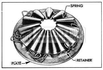
- Install spring retainers through holes in pressure plate, with curves on ends upward, one end in toward center of plate and the other end out from center as shown in figure 4-12.
- Place clutch spring on pressure plate with marks made at disassembly in alignment, then push spring retainers up over the spring. See figure 4-13.
- Place clutch cover over spring and pressure plate with marks made at disassembly in alignment.
- Use Assembly Tool J1039-1 and Assister Hook J1039-2 to hook loop of each spring retainer over ear on clutch cover. See figure 4-14. Do not hammer on tools to get them into place because this will distort clutch cover. Do not stretch retainers any further than is necessary in hook loop over ear on cover. If retainers appear weak or distorted they should be replaced in complete sets to insure even tension.
Assembly of 1954 Buick Series 50-60 Clutch
- Connect pivot screws to release levers with dowel pins and attach release levers to pressure plate with pivot pins locked in place with release lever springs. Springs must be installed over top of release levers. Very sparingly oil release lever pins and sides of levers.
- Coat side surfaces of driving lugs on pressure plate with Lubriplate or Delco Brake Lubricant (this is not brake fluid). Use sparingly excessive lubrication will ruin driven plate facings.
- Place driven plate and pressure plate on fixture used to disassemble 1954 Buick clutch. Place clutch spring seats and clutch springs over bosses on pressure plate, then place clutch cover on pressure plate so that marks made at disassembly are aligned and springs are properly located over bosses in cover. See figure 4-8.
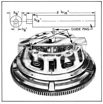
- Press cover down while guiding the release lever pivot screws and the pressure plate driving lugs into the holes and slots in cover. Three guide pins made locally as shown in figure 4-15 may be used to guide the pivot screws.
1954 Buick Assembling the Clutch-Series 50-60
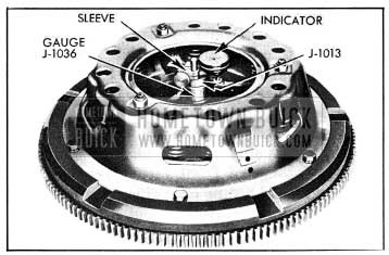
1954 Buick Release Lever Adjustment-Series 50-60
Adjust nut on release lever pivot screw as required to bring indicator to zero reading on the first revolution of indicator hand. Adjust the other release levers in same manner, using care to have all levers within .005″ indicator reading of each other.
Leave A Comment
You must be logged in to post a comment.