SECTION 7-A 1954 BUICK CHASSIS SUSPENSION SPECIFICATIONS AND DESCRIPTION
7-1 1954 BUICK CHASSIS SUSPENSION SPECIFICATIONS
Tightening Specifications
Use a reliable torque wrench to tighten the parts listed, to insure proper tightness without straining or distorting parts. These specifications are for clean and lightly lubricated threads only; dry or dirty threads produce increased friction which prevents accurate measurement of tightness.
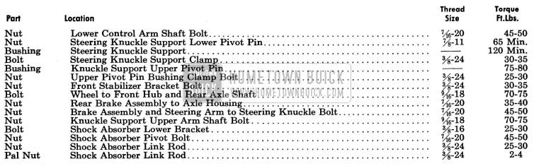
1954 Buick Chassis Tightening Specifications
1954 Buick Wheels and Tires
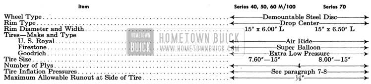
1954 Buick Wheels and Tires Specifications
1954 Buick Springs and Shock Absorbers
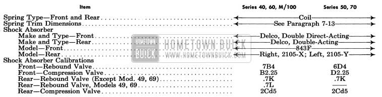
1954 Buick Springs and Shock Absorbers Specifications
1954 Buick Dimensional Specifications
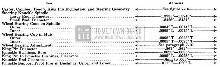
1954 Buick Chassis Dimensional Specifications
NOTE: Dimensions and limits given in these specifications apply to new parts only. Where limits are given, “T” means tight and “L” means loose.
7-2 DESCRIPTION OF 1954 BUICK WHEEL SUSPENSION
1954 Buick Front Wheel Suspension
The 1954 Buick front wheel suspension allows each front wheel to rise and fall, due to change in road surface level, without appreciably affecting the opposite wheel.
Each 1954 Buick wheel is independently connected to the frame front cross member by a steering knuckle, steering knuckle support, lower control arm assembly, and a knuckle support upper arm. See figure 7-1.
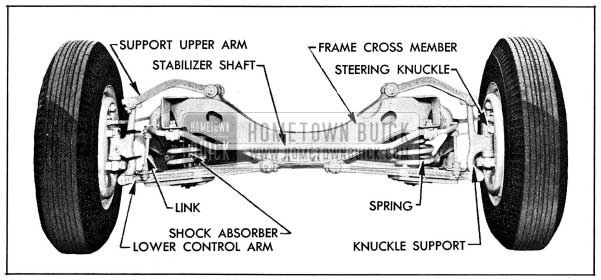
1954 Buick Front Wheel Suspension
The upper and lower arms are so placed and proportioned in length that they allow each knuckle support, spindle, and wheel to move through a vertical plane only. The front wheels are held in proper relation to each other for steering by means of two tie rods which connect to steering arms on the 1954 Buick steering knuckles and to the intermediate rod shown in figure 8-6.
A coil type chassis spring is mounted between the frame front cross member and a spring seat in each lower control arm assembly. A large rubber bumper is mounted on the outer end of each lower control arm to limit travel of the arm during compression of chassis spring.
A similar rubber bumper is mounted on the frame under each upper control arm to limit travel of arm during rebound of 1954 Buick chassis spring.
Side roll of the front end of 1954 Buick chassis is controlled by a spring steel stabilizer shaft. The shaft is mounted in rubber bushings supported in brackets attached to lower flange of each frame side rail. The ends of stabilizer shaft are connected to the front sides of lower control arms by links which have rubber grommets at both ends to provide flexibility at the connections and prevent rattle. See figures 7-1 and 7-8.
The 1954 Buick lower control arm assembly consists of two drop forged steel arms solidly riveted to a stamped steel spring seat to form a rigid V-shaped unit. A small plate riveted above the spring seat serves as a mounting for a rubber bumper and a point of connection for the stabilizer link. Hardened steel threaded bushings are screwed solidly into the inner ends of the forged arms to provide thread-type bearings on the ends of the control arm shaft which is attached to the frame front cross member. A large threaded pivot pin held by a lock washer and nut connects the steering knuckle support to the lower control arm. See figure 7-2.
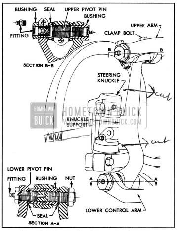
1954 Buick Steering Knuckle Support and Pivot Pins
A large threaded hardened steel bushing is screwed solidly into the lower end of each steering knuckle support to provide a thread type bearing on the pivot pin in outer end of lower control arm. The upper end of knuckle support provides for a threaded, clamp type pivot pin which connects upper end of support to outer end of the knuckle support upper arm. The threaded ends of the upper pivot pin seat in internally threaded hardened steel bushings mounted in outer end of the upper arm. See figure 7-2.
The eccentric type steering knuckle support upper pivot pins provide adjustment for both caster and camber. The threaded pin and bushings permit adjustment of caster by turning the pin, which moves the upper end of knuckle support fore or aft, depending on rotation. The large diameter threaded middle section of pin is eccentric to the ends so that camber is also changed by turning the pin. A hex recess is broached in one end of pin for insertion of the adjusting wrench after removal of the lubrication fitting from the clamped type pivot pin bushing. See figure 7-2.
Rubber seals are installed on upper and lower arm shafts and on lower and upper pivot pins to exclude dirt and water from the threaded bearing surfaces. Lubrication fittings are provided at all bearing locations.
The 1954 Buick steering knuckle is attached to knuckle support by a hardened steel king pin which is locked in knuckle support by a tapered pin. Bronze bushings in steering knuckle provide bearings for king pin. Vertical thrust is taken by a ball bearing between the steering knuckle and knuckle support. The steering knuckle spindle supports the wheel hub with two New Departure adjustable cup and cone ball bearings. The outer end of hub is closed by a cap and inner end is sealed with a packing to exclude dirt and water from bearings. See figure 7-9.
1954 Buick Rear Wheel Suspension
1954 Buick rear wheels are not independently sprung since they are mounted on axle shafts incorporated in the rear axle assembly. The 1954 Buick rear wheels are held in proper alignment with each other by the rigid construction of the rear axle housing. They are held in alignment with the rest of the chassis by the torque tube and radius rod between car frame and the rear axle assembly.
Two coil type chassis springs are mounted between the frame cross member at top of kick up, and spring seats welded to the axle housing near each end. Ride control is provided by a double-acting hydraulic shock absorber mounted on each rear brake backing plate and connected to the frame by a rubber bushed steel link. Side sway of the chassis springs and rear end of frame is prevented by the transverse radius rod. Large rubber bumper and rubber rear axle stops are bolted to lower flange of frame side rails over axle housing to limit travel of axle housing during compression of the 1954 Buick chassis springs. See figure 7-3.
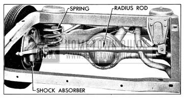
1954 Buick Rear Wheel Suspension
1954 Buick Wheels and Tires
1954 Buick wheels are demountable disc type with the rim welded to wheel disc to form a unit assembly. The 1954 Buick wheels have wide drop center type rims designed to give ample support for the tire sizes used as standard equipment. The rims have tapered tire bead seats which cause tire beads to wedge tightly in place when tires are inflated.
1954 Buick tires on all models are low pressure balloon type, made of a combination of synthetic and natural rubber. Tubes are made of synthetic rubber, which has the advantage of holding air pressure somewhat better than natural rubber. Standard production tire sizes are given in paragraph 7-1.
All 1954 Buick tires and tubes used as standard factory equipment have been worked out with the tire manufacturer for stability. This does not imply that other makes and types of tire and tubes are not suitable for Buick cars, but owing to the large number of tire and tube makes and designs it is impossible for ride and handling calibrations to be worked out for each one.
Tires other than those used as standard equipment may cause a wander. Larger tires will reduce clearance at fenders and be difficult to mount in spare carriers. Tires with more plys may cause hard riding. Some types of “puncture proof” tubes are difficult to balance and may cause “tramp.”
7-3 1954 BUICK SHOCK ABSORBERS
1954 Buick Shock Absorber Types and Installation
The 1954 Buick front shock absorbers are Delco double direct-acting (telescoping) hydraulic type. One shock absorber is vertically mounted inside each front chassis spring. The upper end of each unit is attached by a threaded mounting stem to a bracket on the frame. The lower end is attached by a mounting eye to brackets bolted to the lower control arm spring seat. The upper and lower attachments are insulated with rubber grommets. See figure 7-15.
The 1954 Buick rear shock absorbers are Delco double acting, parallel cylinder hydraulic type. One shock absorber is mounted in each rear brake backing plate, and the arm is connected to the frame by a non-adjustable rubber bushed steel link. See figure 7-3.
Right and left front shock absorbers are identical and interchangeable, however, calibrations may differ between car models. Right and left rear shock absorbers are identical in design but are not interchangeable. All shock absorber calibrations for each model are given under Specifications (par. 7-1) and are also given in the Master Parts List under Group 7.345. On front shock absorbers, the part and calibration code numbers are stamped on the outer tube. On rear shock absorbers the calibration code numbers are stamped on the valve nuts.
Each 1954 Buick front shock absorber is properly filled with fluid and permanently seated during production; therefore, no refilling or other service is possible other than replacement of deteriorated rubber grommets. Rear shock absorbers have filler plugs for periodic checking and maintenance of fluid level.
Front Shock Absorber Construction and Operation
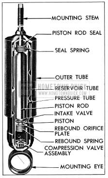
1954 Buick Front Shock Absorber-Sectional View
As shown in figure 7-4, a front shock absorber consists of three concentric tubes, a piston and rod, and valves for controlling hydraulic resistance. The pressure (inner) tube provides a cylinder in which the piston and rod operate. The upper end is sealed by a piston rod seal, and the lower end is closed by the compression valve assembly. This tube is completely filled with fluid at all times. The reservoir (middle) tube provides space for reserve fluid and for overflow from the pressure tube during operation. The outer tube telescopes over the reservoir tube to provide a dust shield.
The 1954 Buick piston, piston rod and outer tube are attached by the mounting stem to the car frame, while the pressure and reservoir tubes are attached as a unit to the lower control arm spring seat through the mounting eye. As the wheel moves up and down with respect to the frame the chassis spring compresses or expands, and the shock absorber is telescoped or extended. This action forces the fluid to move between the pressure and reservoir tubes through small restricting orifices in the valves. The relative slowness of fluid movement imposes restraint on the telescoping or extension of the shock absorber, thus providing the required dampening effect on spring action.
- Compression Stroke Operation. When the chassis spring is being compressed the shock absorber is telescoped, causing the piston to move down in the pressure tube, forcing fluid through holes in the piston. The pressure lifts the intake valve plate, allowing fluid in lower chamber to pass into the upper chamber. As the piston rod moves downward into the pressure tube it occupies space previously filled with fluid and this displaced fluid is forced out of the lower chamber into the reservoir through the restricting orifice in the compression valve. On fast or extreme movements when the fluid flow exceeds the capacity of the orifice, the spring loaded relief valve in the compression valve assembly is forced open to permit more rapid escape of fluid. The amount of compression control is governed entirely by the volume of fluid displaced by the piston rod, and the resistance to chassis spring travel is governed by the area of the orifice and the strength of the compression relief valve spring.
- Rebound Stroke Operation. When the chassis spring expands, or rebounds, the shock absorber is extended and its resistance is instantly effective. As the piston is pulled upward the intake valve plate seats and fluid in the upper chamber is forced through slots in the plate and holes in the piston to build up pressure against the rebound orifice plate. As the pressure increases, the rebound spring is compressed and the orifice plate leaves its seat to permit fluid to pass into the lower chamber. As the piston rod moves upward out of the pressure tube the space previously occupied by the rod is filled with fluid drawn into the lower chamber from the reservoir. A separate intake valve in the compression valve assembly opens to permit return of this fluid.
1954 Buick Rear Shock Absorber Construction and Operation
The 1954 Buick rear shock absorber body contains a fluid reservoir above two parallel cylinders in which compression and rebound pistons operate. Either piston is moved downward by a cam located to bear against the upper end of the piston; while one piston is being moved downward by the cam, the other is moved upward by a heavy coil spring. The cam is mounted on a shaft which extends through one side of the body and is rotated by the shock absorber arm attached to the outer end. The compression piston and cylinder are toward the 1954 Buick shock absorber arm. See figure 7-5.
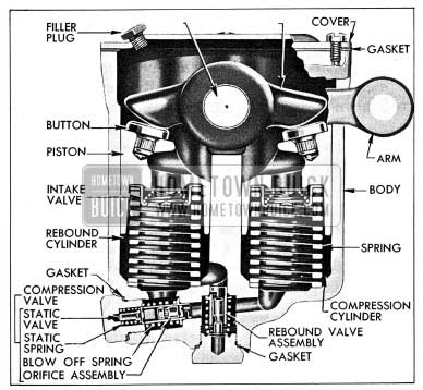
1954 Buick Rear Shock Absorber-Sectional View
During operation the fluid flows from one cylinder to the other through passages drilled in the shock absorber; body, and the rate of flow is governed by the compression and rebound valves located in these passages. An intake valve located in each piston functions to replenish fluid lost by piston leakage as the cylinders are filled under pressure from valve discharge of opposite cylinder.
- Compression Stroke Operation. When the chassis spring is being compressed the shock absorber arm and cam forces the piston down in the compression cylinder. The displaced fluid flows through the compression valve into the rebound cylinder, in which the piston is being moved upward by the coil spring. On slow or relatively light compression the fluid flows through a restricted orifice in the valve assembly, but on fast or extreme movements the valve leaves its seat to permit more rapid flow of fluid. The resistance to chassis spring travel is governed by the area of the orifice and the strength of the compression valve blow off spring.
- Rebound Stroke Operation. When the chassis spring expands or rebounds, the shock absorber arm and cam forces the piston down in the rebound cylinder while the coil spring forces the other piston up in the compression cylinder. Fluid then flows from the rebound cylinder into the compression cylinder through the rebound valve. This valve controls the flow of fluid and governs the resistance to chassis spring travel in the same manner as described for the compression valve.
Leave A Comment
You must be logged in to post a comment.