SECTION 9-D 1954 BUICK POWER BRAKES
9-15 DESCRIPTION OF 1954 BUICK POWER BRAKE MECHANISM
General Description
Wheel brake assemblies used with 1954 Buick power brake mechanism are identical with the regular (foot powered) brake equipment, except that a high pressure type of brake shoe lining is used. This lining is identified by its black colored edge.
The 1954 Buick power brake installation has a “vacuum suspended” type of power brake cylinder in place of the master cylinder used in the regular hydraulic brake system. The brake cylinder is mounted on the car frame under the body and is connected to the brake pedal by an extended push rod. Reserve fluid is carried in a separate reservoir located under the hood, on the left side and connected to the hydraulic section of the brake cylinder by a short pipe.
The 1954 Buick power brake cylinder utilizes engine manifold vacuum in its operation, as described later, therefore it is connected to the intake manifold through pipes and flexible connections. A vacuum pump described later (subpar. d) provides vacuum when the engine is not operating. This pump contains a check valve to prevent loss of vacuum in brake cylinder when neither engine nor pump is operating.
When vacuum exists in the 1954 Buick power brake cylinder, the force required to apply the brakes is provided by the brake cylinder instead of by foot pressure applied to the brake pedal. The driver simply applies light pressure on the pedal to control operation of the brake cylinder. Since high pedal leverage is not required, the brake pedal ratio is materially reduced so that the total pedal travel is almost half the pedal travel of the regular brake mechanism.
The brake pedal pad is approximately level with the accelerator pedal when both are in released position. This convenient location combined with short pedal travel and light pedal pressure makes right foot braking extremely easy and fast because foot movement is reduced to a simple pivot action on the heel.
One or two power brake applications may be made before the vacuum in brake cylinder is exhausted, after the engine and vacuum pump stops. When vacuum does not exist in the cylinder, brakes may be applied through foot pressure on the brake pedal. It should be understood, however, that application of brakes through foot pressure alone requires relatively high effort because the 1954 Buick power brake does not provide as much leverage as the regular (foot powered) brake pedal.
Construction of 1954 Buick Power Brake Cylinder
1954 Buick Power Brake Cylinder
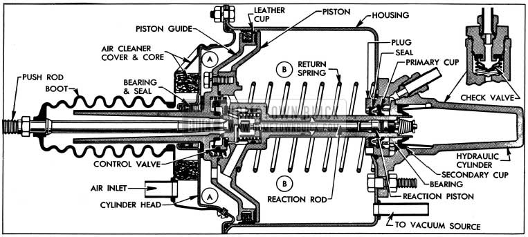
As shown in figure 9-13, the power cylinder head closes the forward end of the cylinder housing to form a large air-vacuum chamber in which the power piston operates. The sleeve (small end) of the power piston extends through seals, cups, and a bearing in forward end if the hydraulic cylinder which is mounted on rear end of cylinder housing. The sleeve (small end) of a guide mounted on the piston extends through a bearing and seal in the cylinder head. The piston is thereby centrally supported so that it can move freely back and forth in the housing. A return spring presses the piston toward the cylinder head.
The rim of power piston carries a spring expanded leather cup to seal against passage of air, so that the piston divides the air-vacuum chamber into two separate chambers which we will call (A) air chamber (B) vacuum chamber. See figure 9-13. Engine manifold vacuum always exists in the vacuum chamber (B) when engine or vacuum pump is running, because it is directly connected to the intake manifold and pump by a pipe. Either vacuum or air at atmospheric pressure may exist in the air chamber (A) depending on operating stages described later; this is governed by the control valve.
The control valve parts are located in the cavity at center of the lower piston and guide assembly. The rubber diaphragm of the floating control valve is pressed over the hub of piston guide and a light coil spring presses the valve disk rearward. The air valve seat slides inside the hub of power piston, and the control spring presses it forward. In the brake released stage, the air valve seat contacts the hub of piston guide and the floating control valve disk.
The cylinder push rod extends through the piston guide sleeve in position to push the air valve seat rearward when brakes are applied. A vacuum valve seat is machined on the power piston in position to be contacted by the control valve disk. Holes in piston and guide provide air or vacuum passages to the air chamber (A). See figure 9-13.
The power piston sleeve contains a reaction piston with rubber cup and a reaction rod. See figure 9-13. Both of these parts slide freely in the sleeve and their movement is governed by the fluid pressure in the hydraulic cylinder, as explained later.
The power piston sleeve and reaction piston together form the hydraulic cylinder piston. Movement of these parts rearward into the fluid filled cylinder displaces a corresponding volume of the fluid, which is forced out into the brake pipes and wheel cylinders. Compensating ports in rear end of piston sleeve permit return of surplus fluid to reservoir when brakes are released. The residual check valve and spring in the hydraulic cylinder maintains static pressure in brake pipes and wheel cylinders.
Operation of 1954 Buick Power Brake Cylinder
Description of 1954 Buick power brake cylinder operation will cover (1) Unapplied Stage (2) Applied Stage (3) Reaction Pressure (4) Poised Stage (5) Releasing Stage.
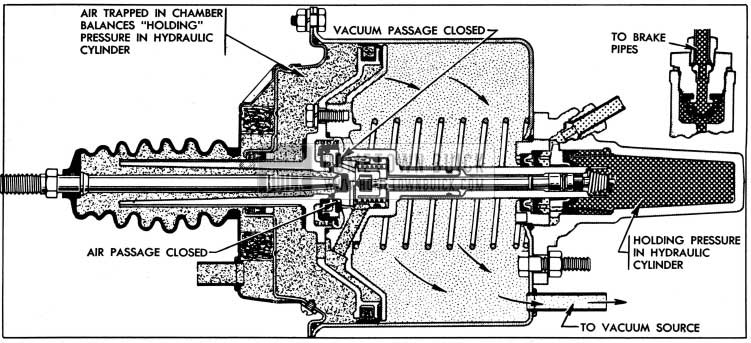
- Unapplied Stage. See figures 9-14 and 9-15.
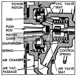
1954 Buick Control Valve Parts
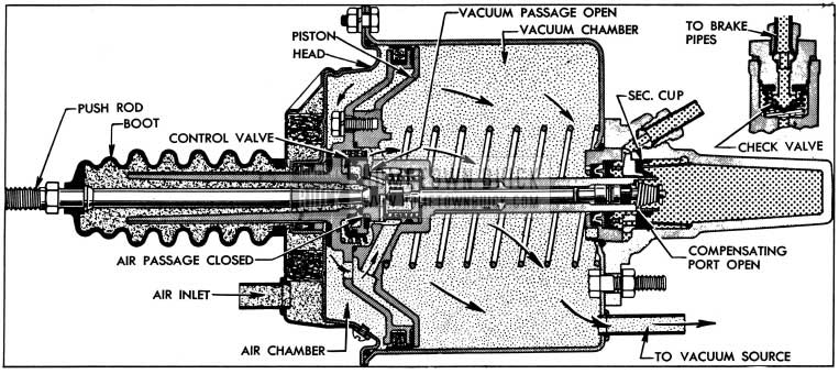
1954 Buick Power Brake Unapplied Stage
The pedal return spring holds the push rod clear of the air valve seat. The control spring presses air valve seat forward against the hub of piston guide and against the floating control valve disk, thereby closing the air passages leading to the air chamber.
The air valve seat holds the floating control valve disk clear of the vacuum valve seat on power piston, thereby opening the passage through the piston and guide between the air and vacuum chambers. Manifold vacuum exists on both sides of power piston therefore pressures are equal on both sides, and the return spring holds the piston forward against the cylinder head.
The compensating ports in rear end of power piston sleeve are forward of the secondary cup, permitting flow of fluid between the reservoir and hydraulic cylinder as required. The residual check valve is seated to maintain static pressure in the brake pipes and wheel cylinders.
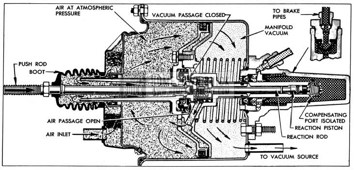
1954 Buick Power Brake Applied Stage
Pressure on the brake pedal moves the push rod rearward into contact with the air valve seat. As the valve seat is moved clear of the piston guide hub a restricted amount of outside air starts moving through this opening, and into the air chamber. The outside air at atmospheric pressure enters through the inlet in air cleaner cover, is filtered as it passes through the felt cleaner core, then flows through the push rod boot and piston guide sleeve to the air valve opening mentioned.
Further movement of push rod and valve seat permits the floating control valve disk to bear against the vacuum valve seat on power piston, closing the vacuum passage, and then the air valve seat moves clear of the control valve disk to permit a large volume of air to enter the air chamber.
With atmospheric pressure on the head side of power piston and vacuum on the other side, the difference in pressure moves the piston rearward, forcing the piston sleeve into the hydraulic cylinder. Escape of fluid into the reservoir is cut off when the compensating ports pass through the secondary cup and the displaced fluid is forced out into the brake pipes and wheel cylinders to apply the brake shoes.
The pressure thus transmitted to the brake pedal opposes the foot pressure applied by the driver. This reaction pressure gives the driver a definite indication or “feel” of the pressure being applied to the brake shoes so that he has positive control over the braking operation at all stages.
1954 Buick Power Brake Poised Stage
Brake apply action and build-up of hydraulic pressure continues only as long as the pedal is kept moving to keep the push rod in contact with the air valve seat. When the push rod stops, the air valve seat stops because it is held against the push rod by the control spring. The piston continues rearward momentarily until the control valve disk contacts the air valve seat and closes the air passage.
The piston stops moving when atmospheric pressure is cut off. Since the control valve disk still bears against the vacuum valve seat on piston, air cannot be exhausted out of the air chamber, therefore the power piston remains stationary or poised, ready to move in either direction. If the brake pedal is depressed for heavier brake application the air valve seat will move rearward and open the air passage. If pedal is released, the following release action will occur.
When the compensating ports in the power piston sleeve pass forward through the secondary cup, any surplus fluid in the hydraulic system can return to the reservoir. The residual check valve spring presses the residual check valve against its seat with sufficient pressure to maintain some residual pressure in the brake pipes and wheel cylinders.
1954 Buick Power Brake Vacuum Pump
A vane type vacuum pump, driven by an electric motor, is installed in the line between the 1954 Buick power brake cylinder and the engine intake manifold to furnish an auxiliary source of vacuum for power brake application whenever the engine is not operating. It supplies a vacuum of 10″ (Hg) in the power brake cylinder in 2 seconds and has a maximum capacity of 20″ (Hg) of vacuum. The pump contains a check valve which maintains a reserve vacuum in the cylinder sufficient for two brake applications with normally light pedal pressure.
The pump motor receives its current through the ignition switch and a cut-out relay. The complete wiring circuit is shown in figure 10-94. When the engine is not running the relay contacts are closed so that when the ignition switch is turned on the pump will operate to supply vacuum for brake application. When the engine is started, voltage supplied by the generator energizes the relay coil which then separates the contacts to cut out operation of the pump. The engine supplies ample vacuum while running; however, if engine should be stalled during operation of the car the loss of generator voltage will permit the relay contacts to close and start the vacuum pump again.
The vacuum pump is mounted on the left fender skirt where it may be reached with the hood raised. Two different designs of pump are optionally used. The “Morvac” pump has four vanes and is shown in figure 9-19. The “Trico” pump has two vanes and a different arrangement of valves, as shown in figure 9-20. Either pump assembly may be used for replacement.
9-16 REMOVAL, INSTALLATION, ADJUSTMENT OF 1954 BUICK POWER BRAKE CYLINDER
Removal, Installation of 1954 Buick Power Brake Cylinder
- Remove cranking motor splash pan.
- Disconnect return spring, remove clevis pin at front end, then remove brake pedal push rod with cylinder push rod attached.
- Disconnect the breather tube which is clamped to inlet tube on power cylinder air cleaner cover.
- Disconnect pipe and hose from vacuum chamber (rear) end of power cylinder.
- Disconnect the reservoir to hydraulic cylinder pipe, allow reservoir and pipe to drain. Disconnect distributor to cylinder pipe and allow to drain. Discard old fluid and cover pipe ends with tape to exclude dirt.
- Remove nuts and lockwashers attaching power cylinder to its support and remove cylinder from car.
- Install 1954 Buick power brake cylinder by reversing the procedure for removal, except for installation of push rod and splash pan. Adjust brake pedal stop and push rod (subpar. b) then bleed hydraulic system (par. 9-7) to complete the installation.
- After bleeding is completed, make sure that reservoir is filled to proper level and check brake system for fluid leaks while applying heavy pressure on brake pedal, with engine running.
Adjustment of 1954 Buick Brake Pedal Stop and Push Rod
- Make certain that brake pedal is properly lubricated and moves freely on its shaft, also that it does not bind on floor mat.
- Adjust brake pedal stop bolt, if necessary, so that the pedal grommet is compressed to 7/8″ height, then tighten the lock nut.
- Slightly wet the end of cylinder push rod with brake fluid before inserting it into the power piston guide sleeve, and be sure that the boot is drawn fully back over the retaining ridge on push rod. Make sure that rear end of boot is properly seated over the flange on air cleaner cover.
- Connect push rod to brake pedal with clevis pin and cotter pin, then check for free movement of pedal and push rod.
- If a bind exists, loosen pedal shaft bracket bolts to permit bracket to shift to a free position, then tighten bolts securely.
- Starting with pedal against its stop, use fingertips only to gently move the push rod rearward until it contacts the air valve seat. Movement or end clearance of rod should be 1/16″. Loosen lock nut and turn the cylinder push rod as required to provide this clearance after lock nut is tightened.
- When checking this adjustment use light pressure when contacting air valve seat because it will be moved if ‘pressure exceeds two pounds. If seat is moved, an incorrect adjustment will be made and dragging brakes will result.
- Connect return spring to push rod and install cranking motor splash pan.
9-17 DISASSEMBLY, INSPECTION, ASSEMBLY OF 1954 BUICK POWER BRAKE CYLINDER
Disassembly of 1954 Buick Cylinder Head, Piston and Guide
NOTE: Refer to figure 9-18 for identification of parts.
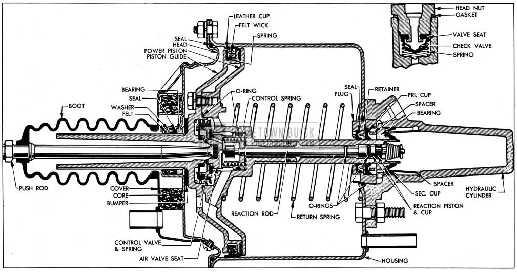
1954 Buick Power Brake Cylinder Parts
- Disconnect boot from flange of air cleaner cover and remove boot and push rod.
- Mount 1954 Buick power brakes cylinder in bench vise with hydraulic cylinder down. Tighten vise only enough to hold cylinder firmly; excessive tightening will crack or distort the cylinder.
- Pry air cleaner cover from cylinder head and remove air cleaner core.
- While holding down on piston guide to keep piston return spring under control, remove four bolts attaching cylinder head to the housing, then free the head from housing.
- Remove cylinder head with the power piston and guide, then remove piston return spring from housing.
- Remove housing and hydraulic cylinder from vise, place open end down in a pan and allow fluid to drain out while proceeding with other work. Discard old fluid.
- Mount piston and head assembly with piston downward on a holding fixture consisting of an 8 inch length of 4 inch pipe, or its equivalent. Lift head off of piston guide, then remove rubber seal from rim of head and rubber bumper from piston guide.
- Bend back lip of leather piston cup, remove felt wick and expander spring.
- Remove three bolts with lockwashers then remove the guide assembly and O-ring from power piston.
- Remove leather piston cup, floating control valve assembly and spring from piston guide.
- Remove air valve seat from power piston, then lift out the control spring.
- Remove cotter pin, retainer and spring from small end of reaction rod, remove reaction rod from piston, then use a drift pin to push out the reaction piston located in lower end of piston sleeve.
Disassembly of 1954 Buick Hydraulic Cylinder
NOTE: Refer to figure 9-18 for identification of parts.
- Remove four nuts and lockwashers which attach the hydraulic cylinder to the housing, lift off cylinder assembly, and remove the cylinder-to-housing O-ring.
- Mount hydraulic cylinder assembly in bench vise with flange end up; do not grip tightly. Unscrew and remove the cylinder plug assembly.
- Remove primary cup, retainer and seal from cylinder plug.
- From hydraulic cylinder remove spacer, piston bearing with secondary cup support washer, secondary cup, and cup retainer.
- Remove head nut with gasket, residual check valve and spring from hydraulic cylinder.
Cleaning, Inspection, Replacement of Parts
As an aid in determining the cause of improper power brake operation, wipe fluid from all rubber parts, the residual check valve, the floating control valve and air valve seat, then carefully examine these parts for nicks, cuts or other damage. After examination discard all these parts.
Thoroughly clean the remaining parts in diacetone alcohol or clean brake fluid.
CAUTION: Do not use anti-freeze alcohol, gasoline, kerosene, or any other cleaning fluid that might contain even a trace of mineral oil, as this could cause serious damage to all rubber parts in the brake system.
Carefully examine the cleaned parts for nicks, burrs, stripped threads, or other damage. Make certain that the small compensating ports in end of power piston sleeve are clear. If these holes are plugged, clean them thoroughly and flush the hydraulic system to remove all dirt.
If the power piston guide sleeve, outer surface of piston sleeve, or inner .surface of sleeve where reaction piston operates show evidence of abrasion, polish out light scores with crocus cloth or very fine polishing paper, then wash and dry thoroughly.
If any parts indicate that heavy abrasive action has resulted from severe contamination of the brake fluid, replace damaged parts and be sure to thoroughly flush the reservoir and wheel cylinder lines.
The Power Brake Cylinder Overhaul Kit (Group 4.898) contains all necessary replacement parts for the power brake cylinder. When reassembling the brake cylinder use all the new parts in the kit regardless of whether the old parts appear fit for use. In addition, replace any other parts which inspection indicates to be unfit for use.
Before installation, wet all O-rings and rubber cups with clean brake fluid, except where O-ring or seal is pre-greased. Do not destroy this application of silicone grease.
Assembly of 1954 Buick Hydraulic Cylinder
NOTE: See figure 9-18 for identification and location of parts.
- Mount hydraulic cylinder in vise with flanged end up.
- Install spring, residual check valve with concave side outward, and head nut with new gasket and check valve seat in the hydraulic cylinder, then tighten nut securely.
- Install secondary cup retainer in cylinder with notched edge inward, then install secondary cup with fiat side outward, using care that cup lip is not turned back at any point.
- Place secondary cup support washer on piston bearing with brake fluid, install bearing with notched face outward, and center the bearing in cylinder bore.
- Place primary cup spacer on piston bearing with notched edge down and center it on bearing so it will not be damaged when cylinder plug is installed.
- Into the cylinder plug install a new seal with fiat side inward, seal retainer with flat side outward, and a new primary cup with fiat side inward against the retainer. Use finger to force outside lip of both the seal and cup down and outward against bore of plug to insure sealing contact.
- Screw plug down into hydraulic cylinder by hand, then tighten it firmly with a wrench but do not use force.
- Place a new O-ring around the cylinder plug, then install hydraulic cylinder on housing with head nut on opposite side from vacuum tube on housing. Install nuts on all studs but do not tighten.
Assembly of Power Piston, Guide, and Head
NOTE: See figure 9-18 for identification and location of parts.
- Place expander spring in groove of power piston guide with bent ends in, so that approximate center of spring is at one of the slots in upper flange of guide, then insert wedge (supplied in kit) through slot to hold spring in place.
- Wrap each end of spring around piston guide and hold with wedges in two side slots. With ends overlapping under fourth slot, install wedge at this point then remove the first three wedges and discard them.
- Saturate the cup lubricating wick in special Power Brake Cylinder Oil supplied with parts kit. Place wick over expander spring with grain of felt parallel to centerline of piston guide. Be sure that ends of wick do not coincide with ends of spring.
- Mount piston guide in holding fixture with sleeve down, install a new leather cup and slide the service ring down over cup. Be sure that leather cup does not ride over the edge of guide and that cup flange lies flat against its face.
- Wet the diaphragm of a new floating control valve assembly with brake fluid, place spring over the retainer, then install these parts on piston guide. Press the diaphragm down over hub on guide, then install a new O-ring over the ridge around valve.
- Install a new metering hole seal over end of reaction rod in bore of stop and press down firmly. Install a new stop washer over other end of rod and seat it firmly against the stop.
- Install a new O-ring in groove of reaction rod, being careful to preserve the silicone grease on O-ring, then install reaction rod in piston with a twisting motion.
- Install a new O-ring in groove of reaction piston, being careful to preserve the silicone grease on O-ring, then install piston over end of reaction rod with the wide land inward, and press it down into bore of power piston sleeve.
- Wet a new reaction cup with brake fluid, place it over end of reaction rod with lip side outward and carefully push it down into bore of piston sleeve.
- Install spring and retainer over end of reaction rod, compress spring and install a new cotter pin to retain these parts.
- Mount piston on holding fixture with sleeve down, then install control spring around the reaction rod stop.
- Install a new O-ring in outside groove of air valve seat, being careful to preserve the silicone grease on O-ring, then install valve seat assembly in power piston above the reaction rod. CAUTION: Use care to avoid damaging the vacuum valve seat on the aluminum piston.
- Place piston guide over the piston and insert the push rod through guide to hold the air valve seat down against reaction rod spring while starting bolts with lockwashers. Use three equally spaced holes in guide; the other three holes are air passages.
- After starting one bolt, remove the expander spring wedge, then install other bolts and tighten all securely, using care not to strip threads in aluminum piston. Remove service ring.
- Place cylinder head on bench with hub end up, then insert a new guide seal into the hub between the bronze bearing and the flat wick retainer washer that are inside the hub; lips of seal must be upward away from the bearing.
- Slide wick retainer washer down against seal, install a new wick in hub between washer and outer lip of hub, then move washer up snug against the wick.
- Apply any grease remaining in seal and wick packing envelopes to inside of hub to provide maximum lubrication for seal, wick and bearing.
Installation of 1954 Buick Power PBrakes iston, Guide, and Head
- Wipe inside of cylinder housing with special 1954 Buick Power Brake Cylinder Oil supplied with parts kit; also oil the leather cup on rim of power piston guide.
- With hydraulic cylinder firmly held in bench vise with housing up, install piston return spring to seat inside the four cylinder flange bolt heads.
- Place a new rubber bumper over piston guide, place a new rubber seal around rim 6f cylinder head, and check lubrication screw and gasket to be sure they are tight in head.
- Set power piston and guide assembly in place with retaining shoulder engaged in return spring, press the assembly down into housing about two inches, then pour the remaining special brake cylinder oil (should be 1-2 oz.) into housing and upon piston guide, but avoid pouring oil into air holes.
- While holding piston guide down, install cylinder head over the guide sleeve and into the housing. Locate head with inspection hole screw on opposite side from the vacuum tube on other end of housing.
- Remove the assembly from vise and press the guide sleeve end down on bench to hold the piston and guide in fully applied position while tightening the hydraulic cylinder stud nuts evenly. The power piston must move freely when all nuts are tight.
- Blow out or replace air cleaner core, install core and cover, placing air inlet tube on same side as inspection hole screw in cylinder head.
- Install new boot on push rod and install rod and boot, placing end of boot .securely over flange on air cleaner cover.
9-18 1954 BUICK POWER BRAKE VACUUM PUMP SERVICE
Lubrication of 1954 Buick Pump
1954 Buick power brake vacuum pumps are filled at the factory with one ounce of special lubricating oil which provides sufficient lubrication of the pump for 5,000 miles of normal operation. The oil supply should be checked every 5,000 miles by removing the filler screw on top surface of pump. Maintain the oil level at 1/4” below top of cover in the “Morvac” pump and within one inch of the top in the “Trico” pump, using Stanotorque oil listed under Group 4.898 in the Master Parts List.
1954 Buick Vacuum Pump Repairs
When it becomes necessary to disassemble the 1954 Buick power brake vacuum pump for inspection or repairs, thoroughly clean all dirt from the exterior, then remove the filler screw and drain the oil from reservoir. Removal of the cover screws will permit easy disassembly of either type pump. Figures 9-19 and 9-20 show all parts and how they should be placed when pumps are reassembled.
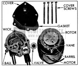
1954 Buick Morvac Vacuum Pump Parts
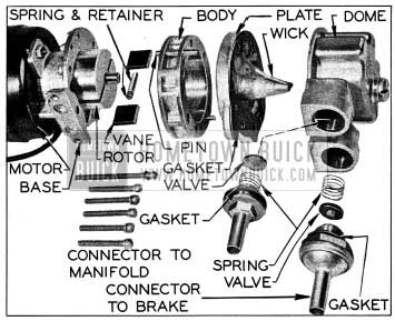
1954 Buick Trico Vacuum Pump Parts
Wiring Circuit, Motor, and Relay Service
The 1954 Buick power brake vacuum pump wiring circuit diagram is given in figure 10-94.
The electric motor may be disassembled for inspection of brushes, commutator, and windings by removing the two long screws and carefully tapping the cover loose from the field frame.
The following specifications must be used when adjusting the relay, No. 1116896.
Point Opening: 017″-.033″
Opening Voltage: 5.7-7.2
After excitation of 12-15 volts, points must reclose at not more than 3.0 volts.
Leave A Comment
You must be logged in to post a comment.