SECTION 8-B 1954 BUICK POWER STEERING GEAR AND PUMP
8-8 1954 BUICK POWER STEERING GEAR AND PUMP SPECIFICATIONS
Tightening Specifications
Use a reliable torque wrench to tighten the parts listed to insure proper tightness without straining or distorting parts. These specifications are for clean and lightly lubricated threads only: dry or ditty threads produce increased friction which prevents accurate measurement of tightness.
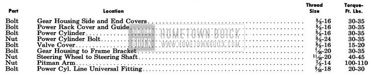
1954 Buick Power Steering Gear Tightening Specifications
1954 Buick Steering Gear Specifications
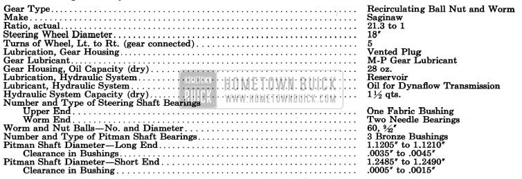
1954 Buick Power Steering Gear Specifications
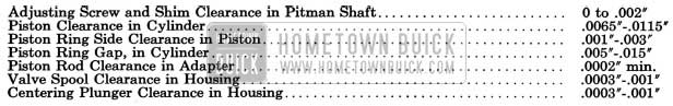
1954 Buick Power Steering Gear Specification
1954 Buick Power Steering Pump Specifications
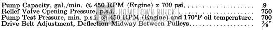
1954 Buick Power Steering Pump Specifications
8-9 DESCRIPTION OF 1954 BUICK POWER STEERING GEAR AND PUMP
1954 Buick Power Steering, standard equipment on Series 70 and Model 100 and available as optional equipment on all other models, consists of a conventional manually operated steering gear to which hydraulic power mechanism has been added. The hydraulic mechanism furnishes additional power to ASSIST the manual operation so that the turning effort required at steering wheel is greatly reduced.
The engine drives the oil pump which furnishes hydraulic pressure. When the engine is not running, or when any part of the power mechanism is inoperative, steering is entirely manual and requires approximately the same effort at the steering wheel as the manual gear used as standard equipment.
With the engine running, steering is entirely manual under conditions which requires an effort of less than four pounds at the steering wheel rim. When a greater effort is required, the power mechanism operates to ASSIST in turning the front wheels. The effort then required at steering wheel rim is thereby limited to a maximum of approximately nine pounds for normal steering and parking conditions) compared to possibly fifty pounds with the standard manual gear. If some abnormal condition requires more work than the power mechanism can do, the driver must assist with increased effort at the steering wheel.
The driver’s effort on the steering wheel is always proportional to the force necessary to turn the front wheels. When the effort on the wheel drops to less than four pounds as the turn is completed, power assistance ceases. When the wheel is released to recover from the turn, the front wheels may return to the straight ahead position in the usual manner without assistance or interference from the power mechanism. Through this conventional steering action the driver always has the “feel” of steering which is essential to confidence in controlling the direction of the car.
It should be noted that 1954 Buick power steering always follows the manual steering action. No steering action is obtained except through the manual guidance of the driver.
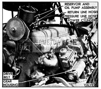
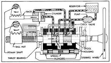
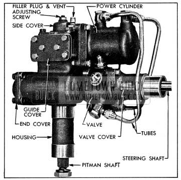
The hydraulic power mechanism added to the steering gear includes a power cylinder and rack connected to a separate gear sector on the steering gear pitman shaft, a hydraulic valve mounted concentric with the steering shaft and operated by the shaft, a high pressure oil pump driven by a belt from the engine, an oil reservoir integral with the pump, and connecting hoses. See figure 8-12.
1954 Buick Power Steering Gear and Pump Installation
The hydraulic units are filled with the same oil as specified for Dynaflow transmissions. The steering gear housing is filled with regular steering gear lubricant.
1954 Buick Power Steering Gear Assembly
The 1954 Buick power steering gear assembly is the recirculating ball nut and worm type, having a ratio of 21.3 to 1.
1954 Buick Power Steering Gear Assembly
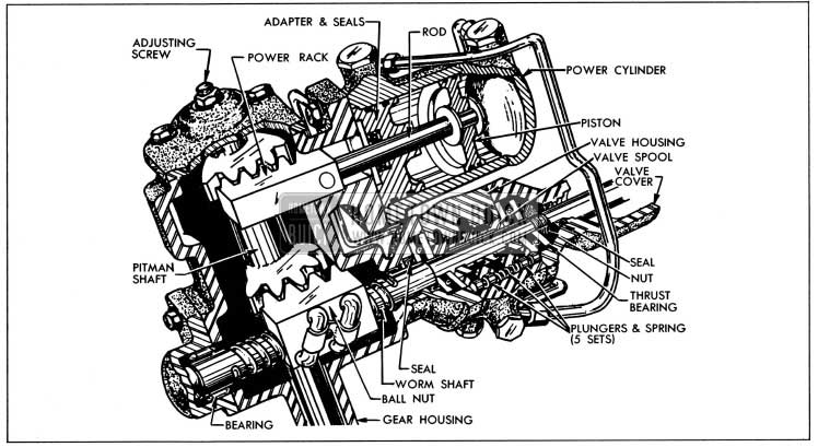
As shown in figure 8-13, the upper end of the pitman shaft is extended and provided with a separate gear sector which meshes with a power rack mounted in the gear housing. The power rack is pinned to the piston rod of the power cylinder, mounted on the rear side of gear housing, and is held in proper mesh with the pitman shaft sector by a guide attached to a shim adjusted housing cover (not shown).
The 1954 Buick power cylinder is a double acting type since oil pressure may be applied to either side of the piston through external tubes connected to the hydraulic valve, described below (subpar. b). An adapter closes the inner end of the cylinder and provides a bearing for the piston rod. The two outer grooves in the circumference of the adapter contain “0” ring rubber seals, and the bore is fitted with a spring loaded rubber seal to prevent escape of oil at piston rod. See figure 8-13. Normal seepage of oil through the bearing is bled back to the hydraulic valve through passages in adapter and cylinder connected to an external tube.
The upper end of steering shaft is supported by a fabric bearing mounted in steering column jacket. The lower (worm) end of shaft is supported in gear housing by two needle bearings. These bearings permit axial (endwise) movement of the shaft.
Axial movement of the steering shaft is opposed by two flat thrust bearings in conjunction with centering springs and plungers contained in the hydraulic valve. One thrust bearing butts against a shoulder and the other bearing is retained by a threaded nut on the worm section of steering shaft. The inner races of both bearings contact the valve centering plungers which are under pressure of the centering springs. See figure 8-13.
Axial movement of the steering shaft under load is limited to approximately .030″ either way from the neutral (no load) position by the clearance between the thrust bearings and the hydraulic valve housing. This axial movement is used to operate the hydraulic valve.
1954 Buick Hydraulic Valve
The 1954 Buick hydraulic valve controls the flow of oil from the pump to the proper side of the power cylinder piston when power assistance is required and cuts off this flow when power assistance is not required. It also regulates the effort at steering wheel within the normal range of four to nine pounds so that this effort is proportional to the force necessary to turn the front wheels, thereby providing the “feel” of steering previously mentioned.
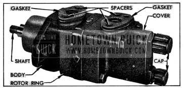
All parts are contained in the valve housing which is mounted on the steering gear housing and is concentric with the steering worm shaft. The housing has one central annular groove connected to the oil pump and two outer annular grooves connected to the reservoir.
A valve spool, having a very close sliding fit in valve housing, is mounted concentric with the worm shaft and between the worm thrust bearings so that it moves with these parts. The spool contains two annular grooves which control the flow of oil between the grooves and oil passages in valve housing. See figure 8-13.
The housing contains five equally spaced pairs of centering plungers which are forced outward against the gear housing and the valve cover by a heavy coil spring located between the plungers. As previously explained, the worm thrust bearings contact the plungers so that axial movement of the worm shaft is opposed by the plungers and springs.
The worm shaft and thrust bearings will move the spool endwise in the valve housing, permitting oil flow to the power cylinder, whenever the thrust load on the worm shaft is sufficient to overcome the preload of the centering springs. The resulting control of the power mechanism will be fully explained in paragraph 8-10.
The check valve located in the hydraulic valve housing permits the oil displaced by the power cylinder piston to bypass the oil pump during manual operation whenever the oil pump is not operating. It also prevents oil from overflowing through the reservoir vent under the same conditions.
1954 Buick Oil Pump
The 1954 Buick Vickers oil pump, which is mounted on the engine in position to be driven by a belt from the crankshaft balancer, converts some engine power into oil pressure which is used by the power cylinder and rack to rotate the pitman shaft.
The pump houses a slotted driving hub or rotor in which twelve vanes slide radially outward to contact the hardened and ground inside surface of a ring. As the shaft and rotor rotates, centrifugal force and fluid pressure against the inner ends cause the vanes to follow the cam contour of the ring, which is so shaped that two opposing pumping chambers are formed. See figure 8-37. In each pumping chamber, the increasing and decreasing pockets formed between the rotor, vanes, and ring propel the oil from the reservoir into a discharge cavity in the pump cover.
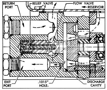
Oil flows from the discharge cavity into the exit port in pump cover through a restricted passage (.1015″ dia.) therefore pressure in the discharge cavity is always greater than in the exit port. A control valve assembly regulates the opening of another passage through which oil may be bypassed back to the reservoir. See figure 8-14. The valve assembly includes a flow valve and a pressure relief valve.
1954 Buick Flow and Pressure Relief Valve Operation
When pump is running without demand for steering pressure, pressure in the discharge cavity is high enough to push the flow control valve open against a spring load of approximately 6.5 pounds. A small orifice leads oil from the exit port into the spring chamber and this pressure tends to close the valve. Since pressure in the discharge cavity is always greater than in the exit port the valve is not closed, and the flow valve action depends on the spring load and the difference in pressure on the inner and outer ends of the valve.
When 1954 Buick power steering is demanded and the steering gear hydraulic valve cuts off free circulation of oil as described later (par. 8-10), the pump pressure builds up rapidly. When pump output pressure reaches a predetermined maximum the increased pressure in the flow valve spring chamber forces the pressure relief valve open, and oil escapes from the spring chamber into the by-pass passage. As oil pressure is relieved in the spring chamber, the high pressure in the pump discharge cavity overcomes the spring load to completely open the flow valve. See figure 8-14. Oil is dumped into the by-pass passage until the line pressure opposing the pump drops below the relief valve setting, permitting this valve to close. The flow valve then resumes normal operation.
The flow valve starts to open at 300-400 RPM of pump and is functioning when pump idles at 465 RPM (450 RPM of engine). The minimum flow the pump must produce is .9 gal. per minute at 465 RPM against a pressure of 700 psi. The flow valve permits a maximum flow of 1.8 gal. per minute at 2000 RPM against a pressure of 50 psi. The pressure relief valve is set for 750-900 psi.
Reservoir and Hoses
The reservoir is mounted on top of the oil pump and provides a reserve supply of oil to assure complete filling of the hydraulic system. The reservoir is vented at the cover bolt by bleed grooves in the washer which permits escape of any air that may be introduced into the system during assembly of the various units.
A pressure line hose and a return line hose connects the oil pump to the hydraulic valve in the steering gear. See figure 8-12. The pressure line hose is reduced in size at the valve end to provide a dampening effect on any turbulence in the oil stream.
8-10 OPERATION OF 1954 BUICK HYDRAULIC POWER MECHANISM
When the 1954 Buick steering wheel is turned, the ball nut must move axially along the worm shaft in order to rotate the pitman shaft and thereby turn the front wheels through the connecting linkage. Movement of the ball nut is opposed by the force necessary to turn the front wheels, consequently the worm shaft tends to move endwise .through the ball nut. The ball nut and worm shaft act like a screw jack to thrust a load against one worm thrust bearing, tending to move the bearing.
Movement of the thrust bearing (and worm shaft) is opposed by the centering plungers and springs in the hydraulic valve, therefore the thrust load must exceed the 290 pound total preload of the five centering springs before the worm shaft can actually move endwise. A pull of four pounds on the steering wheel rim produces a thrust load of 290 pounds, consequently the worm shaft will move endwise only when the force necessary to turn the front wheels requires an effort of more than four pounds at the steering wheel.
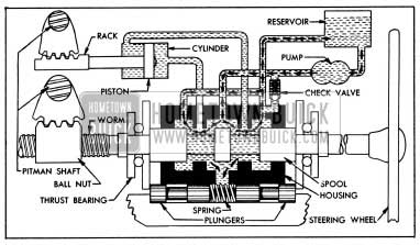
Since movement of the hydraulic valve spool is controlled by the worm shaft and thrust bearings it remains in the neutral or centered position in valve housing whenever the effort applied to steering wheel is less than four pounds. In this case the oil merely circulates from the pump through the valve and reservoir without having any effect on the steering operation. See figure 8-15. Although the power cylinder is filled with oil there is no interference with manual steering because the oil displaced by the piston can flow from one side of the piston to the other through the hydraulic valve.
1954 Buick Oil Circulation Without Power Application
When the 1954 Buick steering wheel is turned left with an effort greater than four pounds, the resulting thrust load compresses the centering springs and the worm shaft moves the spool upward in the valve housing. The spool then routes the oil flow from the pump into the upper end of the power cylinder. The passage to the lower end of power cylinder is left open for return of oil to the reservoir. See figure 8-16.
1954 Buick Oil Circulation During Power Application on a Left Turn
Flow of oil into the power cylinder is resisted by the piston because of its connection to the pitman shaft. The oil pump then builds up just enough pressure to overcome this resistance so that just enough power is applied to rotate the pitman shaft.
Since the pitman shaft is also geared to the ball nut on the worm shaft it is obvious that the pitman shaft cannot turn unless the steering wheel is also turned. Thus, 1954 Buick power steering cannot be applied without manual steering.
As the pump pressure builds up, oil pressure is also directed against the inner ends of the centering plungers. This pressure, added to the centering spring preload, tends to force the spool back to the neutral position. Since the pump pressure builds up in proportion to the force necessary to turn the front wheels, the corresponding pressure on the plungers creates a reaction that must be overcome by effort on the steering wheel. In this way, the effort required at the steering wheel is regulated in proportion to the resistance of the front wheels, giving the “feel” of steering previously mentioned.
The effort on the steering wheel naturally drops to less than four pounds as the turn is completed; therefore the centering springs and plungers return the valve spool to the centered position, thereby cutting off application of oil pressure to the power cylinder. When the spool returns to the centered position, steering becomes entirely manual. The oil merely circulates through the hydraulic valve as shown in figure virtually no resistance to oil flow.
1954 Buick power steering on a right turn is accomplished in the manner described except that the worm thrust is in the opposite direction, therefore the valve spool moves down to route oil to the lower end of the power cylinder so that power will be applied to turn the pitman shaft in the opposite direction.
When the front wheels strike an obstruction which kicks them to the left, the force is transmitted through the steering linkage and pitman shaft to exert a downward thrust on the ball nut and worm shaft; this is opposite to the direction of thrust when the steering wheel is turned left. If the thrust load exceeds 290 pounds, the valve spool will move down to route oil flow to the lower end of power cylinder, thereby applying opposing power to counteract the leftward movement of the front wheels. The opposite action occurs when the wheels are kicked to the right. In this manner, the power mechanism counteracts road shock before it is transmitted to the steering wheel.
The check valve located in the hydraulic valve housing remains closed when the oil pump is operating. When the oil pump is not operating and the steering gear is operated manually, the oil displaced by the power cylinder piston flows through the check valve and back into the central groove of valve housing without passing through the reservoir and pump. The oil bypasses the pump which would obstruct its flow. This feature also prevents overflowing of oil through the reservoir vent.
8-11 TROUBLE DIAGNOSIS – 1954 BUICK POWER STEERING GEAR AND PUMP
This paragraph will cover only those causes of trouble which may be due to the hydraulic power mechanism causes which are due to the mechanical components of the steering gear, linkage, and front suspension are the same as described for the standard steering gear in paragraph 8-3.
Before assuming that the hydraulic power mechanism is at fault, make certain that the mechanical components are in proper condition. The mechanical items include: Front wheel alignment, tire condition and pressure, wheel bearing adjustment, lubrication and adjustment of steering linkage, and proper alignment of steering gear in mountings to eliminate binding.
Excessive Play or Looseness in Steering Mechanism
- Excessive lash between pitman shaft sectors and the ball nut or power rack (par. 8-12).
- Loose worm thrust bearing adjustment or sticking valve spool, requiring removal of gear assembly (par. 8-14).
Front Wheel Shimmy
- Air in hydraulic system, requiring bleeding by operating pump and steering gear until oil stops foaming in reservoir.
- Excessive lash between pitman shaft sectors and the ball nut or power rack (par. 8-12).
Failure to Recover from Turns
When the steering wheel is released at completion of a turn the front wheels should return to the straight ahead position in the same manner as permitted by the manual steering gear. In cases of failure to recover from turns check the following items.
- Tightness of kingpins in bushings. Lubricate or otherwise free up.
- Heavy adjustment of steering gear or steering linkage (par. 8-12).
- Tight steering shaft upper bearing. Replace bearing.
- Loose worm thrust bearings; this may cause snapping noise in the gear. Remove gear assembly for proper adjustment (par. 8′-14).
- Thrust bearings reversed at assembly. Remove gear assembly and install parts correctly (par. 8-14).
- Improper O-Ring seals on each side of valve or improperly machined grooves in valve spool or valve housing. Install proper seals or replace valve assembly (par. 8-14).
- Tip interference between center tooth of pitman shaft sector and mating tooth of ball nuts. This will be evident when lashing the gear as the scale reading approximately 120 degrees off center, left or right, will be higher than on center. This condition requires replacement of pitman shaft.
Rattle or Chuckle in 1954 Buick Steering Gear
- Excessive lash between pitman shaft sectors and ball nut or power rack (par. 8-12). NOTE: A very slight rattle may occur on turns because of the increased lash off the “high point.” This is normal, and lash must not be reduced below specified limits to eliminate this slight rattle.
- Excessive clearance at steering shaft upper bearing in column jacket.
1954 Buick – Hard Steering When Parking
NOTE: It is a normal condition to feel an increase in parking effort if the hydraulic oil temperature exceeds 170° F. The oil temperature may exceed 170°F after excessive turning or on very hot days.
To determine whether hard steering actually exists, place car on clean dry floor, apply brakes, and with engine idling turn-steering wheel from side to side to bring oil temperature to approximately 170°F. Apply Gauge J 5178 (15 lbs.) to a spoke at rim of steering and check the pull required to turn the wheel steadily, with gauge held at 90 degrees to the spoke.
If the pull required to turn the steering wheel exceeds 10 pounds, check the following possible causes:
- Pump drive belt loose. Adjust tension (par. 8-13).
- Low oil level in reservoir. Fill to proper level (par. 1-1). NOTE: If oil level is excessively low, check all hydraulic system lines and joints for evidence of external leakage of oil.
- Air in hydraulic system. Tighten valve cover bolts and all oil line connections on steering gear and pump, then bleed the hydraulic system by operating the pump and steering gear until oil stops foaming in reservoir.
- Insufficient oil pressure. If the preceding suggestions do not reveal the cause of hard steering it will be necessary to make the following tests of oil pressure (subpar. f).
Testing Hydraulic Oil Pressure
- Disconnect the pressure line hose at oil pump, attach Gauge J 5176 to pump and connect the hose to end of gauge where the valve is located. See figure 8-17.
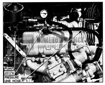
1954 Buick Pressure Gauge J 5176 Installed
- First test (step 2) pressure low, and second test (step 4) pressure normal- indicates faulty external oil lines or steering gear (subpar. g or h).
- First test (step 2) and second test (step 4) pressures equally low-indicates faulty oil pump (subpar i).
- First test (step 2) pressure low, and second test (step 4) pressure higher but below normal indicates faulty pump and also faulty external oil lines or steering gear (subpar. g, h, i).
Low Oil Pressure Due to External Oil Lines
- Loose connections. Clean and tighten all connections and test for oil leakage.
- Leakage at hose unions or oil tube elbows. Remove leaking unions or elbows and install new “0” ring seals.
Low Oil Pressure Due to 1954 Buick Steering Gear
- Leakage at worm shaft seal or cylinder piston rod seal, evidenced by an accumulation of hydraulic oil in gear housing. Leakage at valve cover seal, evidenced by oil dripping from top of valve cover. Remove gear assembly for replacement of seals (par. 8-14).
- Pressure loss in hydraulic valve or power cylinder. Remove gear assembly for disassembly and inspection (par. 8-14).
Low Oil Pressure Due to Pump
- Pump drive belt loose. Adjust tension (par. 8-13).
- Low oil level in reservoir. Fill to proper level (par. 1-1).
- Oil too light. Change to specified Dynaflow oil (par. 1-4).
- Loose pump assembly bolts. Tighten all pump bolts.
- Faulty internal pump condition such as dirt or sludge, sticking or scored relief or flow control valve, worn rotor parts, shaft oil seal leakages. Remove pump and disassemble for inspection (par. 8-15).
1954 Buick Oil Pump Noisy
- Air in hydraulic system. Tighten all external line connections and bleed hydraulic system by operating the pump and steering gear until oil stops foaming in reservoir.
- Drive belt too tight. Adjust tension (par.8-13).
- Oil too heavy. Change to specified Dynaflow oil (par. 1-4).
- Sludge and dirt in pump. Remove pump and clean out. (par. 8-15).
- Bearings, shaft or other rotating parts worn. Remove pump and disassemble for inspection (par. 8-15).
8-12 ADJUSTMENT OF 1954 BUICK POWER STEERING GEAR IN CAR
- Disconnect 1954 Buick pitman arm from intermediate tie rod and check tightness of pitman arm nut with an 18″ wrench. NOTE: Never attempt to adjust steering gear with pitman arm connected to intermediate rod.
- Turn steering wheel slowly through its full travel to check for binding, tight spots or uneven action.
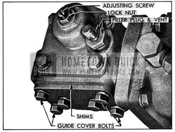
- Loosen the four corner bolts of power rack guide cover about one half turn or just enough to assure lash between the power rack and pitman shaft sector. See figure 8-18. NOTE: If bolts are loosened too much, the rack will bind on sector teeth.
1954 Buick Power Steering Gear Adjustments
If upper bearing is too deep or too tight in column jacket to be removed easily, drill a hole in lower side of bearing shell and insert a self-tapping metal screw to provide a means of pulling bearing. Be very careful to avoid marring steering shaft.
Write down the actual scale reading.
Write down the actual scale reading.
If reading is not within these limits, add or remove cover shims (fig. 8-18) as required to obtain the specified pull through the “high point” or no lash range. Guide cover shims are available in .003″ and .005″ thicknesses so that they may be combined to produce any required total thickness. NOTE: To avoid spilling lubricant, it is advisable to remove filler plug with vent attached (fig. 8-18) and use a clean oil gun to draw out approximately 3/4 pint of lubricant from the gear housing before removing the guide cover.
8-13 REMOVAL AND INSTALLATION OF 1954 BUICK STEERING GEAR AND PUMP
Removal and Installation of 1954 Buick Steering Gear Assembly
- Place car cover over left front fender then remove the battery and battery shield.
- Disconnect the pressure and return line hoses from the hydraulic pump and immediately install shipping caps on pump fittings to retain oil in pump. Drain hoses and install shipping plugs to prevent dripping of oil.
- Continue with removal, following the same procedure as given for the manual gear assembly in paragraph 8-6.
- Install the gear assembly by reversing the procedure for removal, paying particular attention to the points given in paragraph 8-6 (subpar. b) where applicable. The following additional points must be observed with 1954 Buick power steering gears.
- When installing column jacket assembly over steering shaft place Bearing Protector J 5159 over serrated end of shaft to avoid damage to steering shaft upper bearing in jacket.
See figure 8-19. Slot in lower end of jacket must engage dowel pin in hydraulic valve cover.
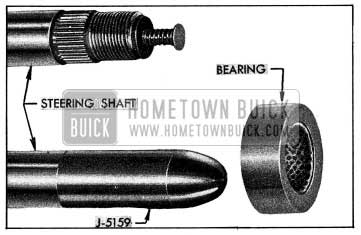
1954 Buick Steering Shaft, Bearing, and Bearing Protector
Removal and Installation of 1954 Buick Oil Pump
- When removing the pump, use shipping plugs and caps to cover the hose connectors and unions on pump and plug open ends of the pressure and return line hose to avoid entrance of dirt.
- When pump is installed in engine, adjust drive belt to allow 3/8″ deflection with thumb pressure midway between pulleys. See figure 2-37.
- Connect the pressure line hose to the lower union on pump cover and connect the return line hose to the upper union.
- Fill the reservoir to proper level with specified Dynaflow oil (par. 1-1).
8-14 DISASSEMBLY, INSPECTION, ASSEMBLY OF 1954 BUICK POWER STEERING GEAR
Disassembly of 1954 Buick Steering Gear
- Thoroughly clean exterior of gear assembly with a suitable solvent.
- Remove two hoses, two large valve-to cylinder tubes, and the small bleed line tube, then allow oil to drain from hydraulic valve and power cylinder. Remove filler plug with vent and drain lubricant from gear housing. See figure 8-20.
1954 Buick Left Side of Power Steering Gear Assembly
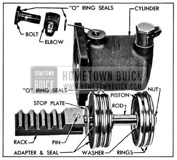
1954 Buick Power Cylinder and Rack Parts
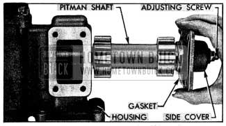
1954 Buick Removing Pitman Shaft and Side Cover
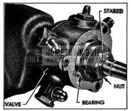
1954 Buick Thrust Bearing and Nut
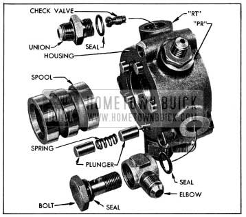
1954 Buick Hydraulic Valve Parts
Cleaning and Inspection of 1954 Buick Power Steering Gear Parts
- Thoroughly wash all parts in clean kerosene or solvent and wipe dry with clean, lintfree cloths.
- Inspect steering shaft for wear or brinelling in ball and needle bearing races, which would require replacement of shaft.
- Support steering shaft in V-blocks and check it for straightness. Run-out at center should not exceed .020″.
- Inspect teeth of ball nut and all sector teeth of pitman shaft. If teeth are excessively worn or scored replace the part. Replace pitman shaft if serrated end is twisted.
- Check fit of pitman shaft adjusting screw and shim in the slot in end of pitman shaft. With shim in place, screw head must be free to turn in slot with no perceptible end play to .002″ loose. If end play is excessive, selectively fit a new shim; these are furnished in four different thicknesses.
- Inspect pitman shaft bushings in gear housing and side cover. Replace bushings in housing and replace cover assembly if bushings are worn excessively.
- Remove worm seal from gear housing with a punch and use Installer J 5189 to install a new seal with spring side outward. See figure 8-25.
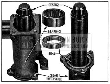
1954 Buick Installing Bearing and Seal in Gear Housing
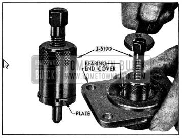
1954 Buick Removing Bearing from End Cover
Use Installer J 5191 to install the new bearing. This tool has a shoulder to locate the bearing at proper depth in cover. See figure 8-27.
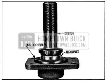
1954 Buick Installing Bearing in End Cover
- Replace 1954 Buick pitman shaft seal, installing new seal with feather edge toward inside of gear housing.
- Inspect piston rod, teeth and guide bearing surface of power rack, and rack guide for excessive wear or scoring. If necessary to replace piston rod or rack, drive out the coupling pin and use new pin to connect new parts. Stake rack at three places on each side to retain the pin, and file down burrs raised by staking.
- Inspect power cylinder bore for scores or other damage. Remove any burrs from the chamfered edge to prevent damage to seals on the adapter during assembly.
- Inspect piston rings for scores or breaks.
- Inspect piston rod seal in power cylinder adapter. If seal is damaged or of doubtful condition drive it out, and remove the O-Ring seal from groove in adapter bore. Install new O-Ring seal in groove, then press a new piston rod seal into adapter with the spring side inward.
- Inspect hydraulic valve housing, spool, and centering plungers for scores, nicks or burred edges. Slight stickiness of spool or plungers in housing may be corrected by polishing with crocus cloth. Do not use emery cloth. Replace damaged parts and make sure that all parts slide freely in housing. Valve spool and housing are selectively fitted and must be replaced as an assembly.
- Test the check valve by blowing through both ends. Ball should seat when blowing through small end, and allow passage of air when blowing through slotted end of valve body.
- Remove the seal and the control shaft lower bearing from hydraulic valve cover with a punch. Press a new bearing into cover. Use Installer J 5188 to press the new seal into cover, with spring side of seal outward toward shoulder of tool. See figure 8-28.
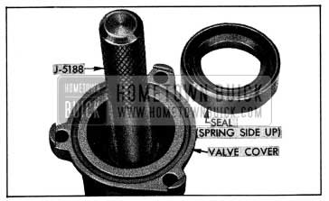
1954 Buick Installing Valve Cover Seal
Assembly of 1954 Buick Power Steering Gear
NOTE: Make sure that all parts are absolutely clean, and lubricate parts with clean engine oil during assembly.
- Place steering shaft on bench with upper end to your right, then install ball nut on worm so that when teeth are uppermost the deeper side of teeth are toward you. Install 30 balls in each circuit of the worm, nut, and return guides, and install guide clamp.
- Run ball nut to the upper end of worm, then install steering shaft in gear housing, using care to avoid damaging worm seal in housing. Install end cover with new gasket.
- Install lower thrust bearing over steering worm with the large race outward, and place a new O-Ring seal in groove in face of gear housing.
- Install check valve in “RT” port of the hydraulic valve housing and tighten securely. See figure 8-24.
- Install hose unions with new O-Ring seals, placing union with smaller outer threads in valve housing port marked “PR” and other union in port marked “RT”. Install elbows and bolts at the other ports with new seals on both sides of each elbow. Do not tighten these parts.
- Place valve housing on bench with the return (“RT”) port to the right of the pressure (“PR”) port, then carefully install the valve spool with the counterbored end upward as shown in figure 8-29. NOTE: The spool is a very close fit in housing and must be started carefully to avoid jamming. Do not force spool into place.
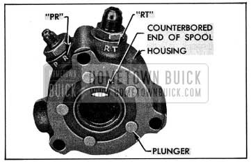
1954 Buick Spool Installed In Valve Housing
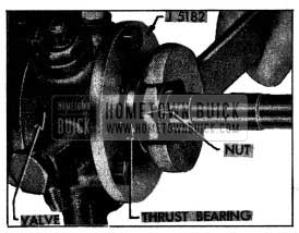
1954 Buick Tightening Worm Bearing Nut
NOTE: Check for possible looseness of bearing adjustment by attempting to turn bearing outer race by hand; a very heavy drag should exist.
- Remove 1954 Buick steering wheel and Adapter J 5182, place Protractor J 5159 over threaded end of steering shaft (fig. 8-19) and install hydraulic valve cover with a new O-Ring seal properly seated in its groove. With dowel pin in cover placed on opposite side from the “RT” port in valve housing install cover bolts with lockwashers and tighten securely.
- Place adjusting screw and shim in slot of pitman shaft, install side cover with a new gasket, and install lock nut finger tight on screw.
- Place gear assembly on left side, tum steering shaft until ball nut teeth are centered on pitman shaft bushings, and tilt nut slightly toward side cover opening. See figure 8-31. Hold pitman shaft with the gear sectors straight down as it is installed in gear housing; use care to avoid damaging pitman shaft seal in gear housing as shaft is pushed through it. Install side cover and tighten bolts securely.
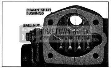
1954 Buick Position of Ball Nut for Installation of Pitman Shaft
Write down the scale reading, which should be between 1/2 and 3/4 pound.
- Turn steering wheel back to near center and again use the scale to check the pull required to turn the wheel steadily through the “high point” or no-lash range.
- The pull through the “high point” (step 20) should be 1/2 to 3/4, pounds greater than the pull in the lash range (step 19). Turn adjusting screw as required to obtain this difference in pull after lock nut is securely tightened.
Write down the final scale reading for use later.
- Install new O-Ring seals in both grooves of power cylinder adapter. Place stop plate on piston rod, then install Rod Inserter J 5193 to protect the seal as rod is pushed through seal and adapter. See figure 8-32. Install thrust washer, piston with rings, thrust washer, and safety nut on piston rod and tighten securely.
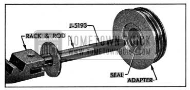
1954 Buick Application of Rod Inserter J 5193
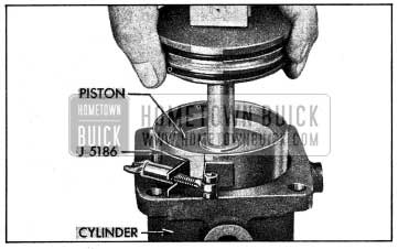
1954 Buick Installing Piston With Ring Compressor View
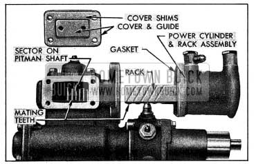
1954 Buick Position of Rack and Sector for Installation of Power Cylinder
NOTE: It is desirable to fill the valve, tubes and cylinder as completely as possible to exclude air. Rapping the valve and cylinder with a soft mallet during the filling operation will aid in eliminating air pockets.
- Fill the gear housing to filler opening with Multi-Purpose Gear Lubricant specified for synchromesh transmissions (par. 1-1) and install filler plug with vent.
8-1 5 DISASSEMBLY, INSPECTION, ASSEMBLY OF 1954 BUICK VICKERS OIL PUMP
Disassembly of 1954 Buick Vickers Pump
- Use shipping caps to cover the hose unions on pump to exclude dirt, then thoroughly clean exterior of pump.
- Remove reservoir cover, drain out all oil, then remove reservoir which is attached with four bolts on the inside. Remove two cork gaskets, being careful not to lose the spacer located in each bolt hole. See figure 8-35.
1954 Buick Pump with Reservoir Removed
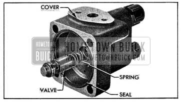
1954 Buick Pump Cover and Control Valve
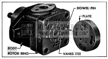
1954 Buick Pressure Plate, Ring, Rotor and Vanes
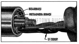
1954 Buick Removing Bearing Retaining Ring
Shaft must be pressed through the inner ball bearing which is located in body behind the shaft seal. See figure 8-39.
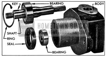
1954 Buick Drive Shaft, Bearings, and Seal
Cleaning and Inspection of 1954 Buick Vickers Pump Parts
- Wipe the bearing and shaft assembly with clean cloths; do not soak in cleaning solvent as the lubricant sealed into the bearing may be diluted by solvent and wipe dry with clean lint free cloths.
- Inspect the drive shaft for wear and check both ball bearings for roughness or noisy operation. If the large bearing must be replaced, press the new bearing on shaft with a tool that applies pressure on the inner race only.
- Check fit of vanes in slots of rotor; vanes must slide freely but snugly in slots. Tightness may be relieved by thorough cleaning or removal of irregularities. Replace rotor if excessive looseness exists between rotor and vanes, and replace vanes if they are irregularly worn or scored.
- Inspect all ground surfaces of the rotor ring for roughness or irregular wear. Slight irregularities may be removed with a hard Arkansas stone. Replace ring if inside cam surface is scored or worn.
- Inspect the fiat faces of the pressure plate and body for wear or scoring. These faces may be repaired by lapping until smooth and fiat, after which all lapping compounds must be thoroughly washed away.
- Inspect the control valve bore in pump cover for scores or other damage. Hair line scratches are normal but heavy scratches or scores should be cleaned up with a cylindrical hard Arkansas stone. If this cannot be done satisfactorily, replace the cover.
- Inspect ground surfaces of the control valve for scores. Hair line scratches are normal but heavy scratches or scores should be cleaned up with a hard Arkansas stone. Replace the valve assembly if it is badly scored or if it is found to be the cause of low pump pressure. It is not practicable to disassemble, clean and assemble the valve parts and assure proper pressure control. Make certain that control valve slides freely in bore of pump cover.
Assembly of 1954 Buick Vickers Pump
Assemble the pump by reversing procedure for disassembly, paying attention to the following items:
- Make sure that all parts are absolutely clean, and lubricate all moving parts with clean engine oil during assembly.
- Use new seals and gaskets.
- Make certain that the bearings and shaft seal are firmly seated in their proper positions, after the inner ball bearing is installed, the shaft seal must be installed with the two small holes in casing toward the outside. Use a tube or shaft lo/s” in diameter to apply pressure against outer edge of seal during installation.
NOTE: A sleeve is inserted in each seal at the factory to prevent the spring from pushing the rubber element out of casing. This sleeve must be left in place until seal is installed. If pump shaft cannot be immediately installed after seal, reinstall sleeve in seal with rounded end inward.
- Install the outer bearing retaining ring with the bevelled side outward.
- The rotor ring must be installed over the dowel pins with the embossed arrows pointing in a counter clockwise direction as viewed from rear end of pump. See figure 8-37. NOTE: When viewed from the front or shaft end of pump, the arrows on ring point in a clockwise direction, which is the direction of rotation of pump shaft.
- Install vanes in slots of rotor with the rounded edge outward toward the ring.
- When pump cover is installed, turn cover bolts down snug only. Install the reservoir with new gaskets, being sure that a spacer is located in each bolt hole (fig. 8-35), then tighten reservoir and pump cover bolts securely. This is necessary to assure proper alignment of the cover, reservoir; and body.
- When assembly is completed, rotate pump shaft to make sure of free movement, then install caps on hose unions to exclude dirt until pump is installed.
My 54 Buick special hardtop riv steering went out spins freely to the left